Project 3
Design and simulation of buck converter for auxiliary load in EV.
Buck converter:
Step down DC/DC converter which converts unregulated dc into regulated dc which is lower than the supply voltage.
Modes of operation:
- when the switch is closed inductor current increase linearly till the switch is ON. Vs =Vo
- when the switch is open inductor behaves like the current source current freewheels through the diode across Vo.
Given Data:
Input Voltage =48 v
output voltage =12 v
Load current = 10A
Calculations:
R = Vo/iL = 12/10 = 1.2 ohms
To determine the duty ratio
Duty Ratio = Vo /Vin = 12/48 =0.25 or 25%
To determine inductance value:
Assume the switching frequency is 40KHz
Lmin = (1-D)R /2f = (1-0.25)*1.2 /2 *40*10^3
=11.25 micro Henry
Assuming the inductance value is 25% higher for the inductor current to be continuous,
Lmin =(25/100)*11.25
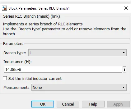
= 14.06 microhenry
To determine Capacitance value:
C = (1-D) / (8*l*r*f^2)
=(1-0.25) / (8*14.06*10^-6*r*40*40*10^6)
Assume ripple to be 5%,
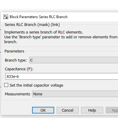
= 833 microFarad.
From the above-calculated parameters, we design a buck converter model below
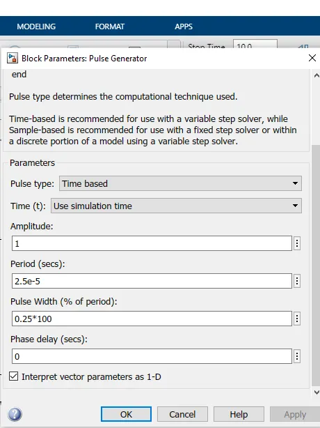
Pulse Generator
Parameters entered based on calculated duty cycle and frequency
Inductance:
Capacitance:
Simulink Design of Buck converter:
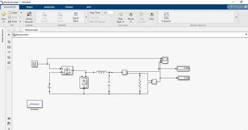
Output:
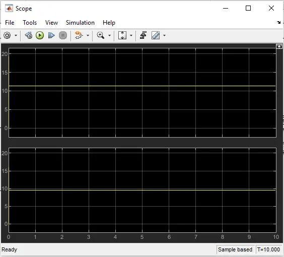
We are getting voltage and current from the above waveform is
- Voltage = 11.34 V
- Current = 9.45 A