Project 3
Aim:
Design and simulation of Buck converter for Auxiliary load in EV.
- Input voltage is 48V, Output voltage is 12 V
- Load current is 10A
- Calculate Duty ratio and Load(use Resistor as Load)
- Calculate L,C
THEORY:-
Buck converter:-
A buck converter (step-down converter) is a DC to DC power converter which steps down voltage - often creating 5V DC from perhaps a 12 or 24V DC source.
- Switching converters (such as buck converters) provide much greater power efficiency. as DC-to-DC converters than linear regulates, which are simpler circuits that lower voltages by dissipating power as heat, but do not step up output current.
- The efficiency of buck converters can be very high, often over 90%, making them useful for tasks such as converting a computer's main supply voltage, which is usually 12 V, down to lower voltages needed by USB, DRAM, and the CPU, which are usually 5, 3.3 or 1.8 V.
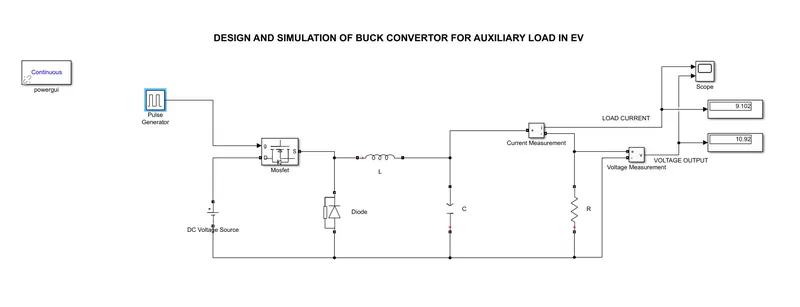
Simulation of Buck converter is done as shown above
Block used:Battery,Pulse generator,MOSFET,Diode,Inductance,Capacitance,Resistance Current measurement,voltage measurement,scope and power gui
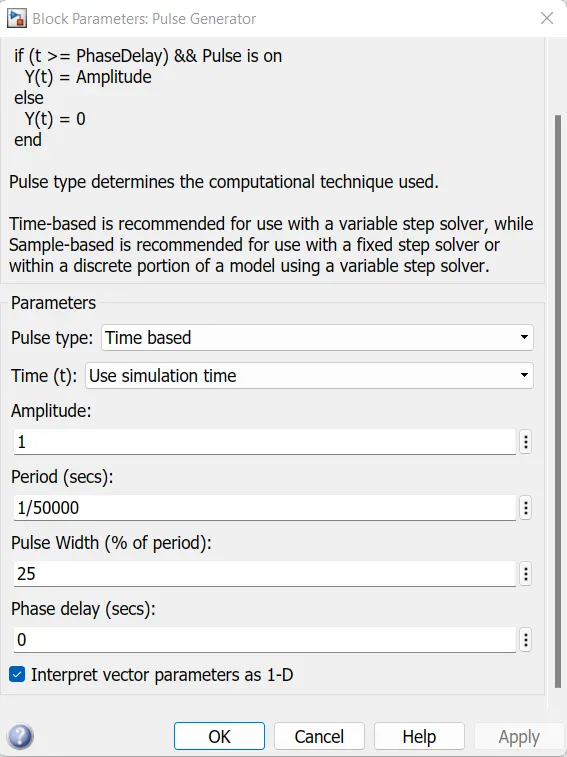
- Pulse generator:In pulse generator we set switching frequency 50KHz and pulse width25% and fed to MOSFET
-
DC voltage source - we can use DC voltage source because we need DC voltage in output & Buck converter is DC-DC converter. This block is used here for the Input providing 48V. The DC Voltage Source block represents a constant voltage source whose output voltage value is independent of the current through the source.We set the value of DC voltage source to be 48 V. It can be measured by voltage measurement.
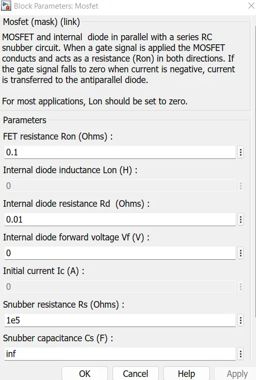
- MOSFET:- MOSFET and internal diode in parallel with a series RC snubber circuit. When a gate signal is applied the MOSFET conducts and acts as a resistance (Ron) in both directions. If the gate signal falls to zero when the current is negative, the current is transferred to the antiparallel diode.
-
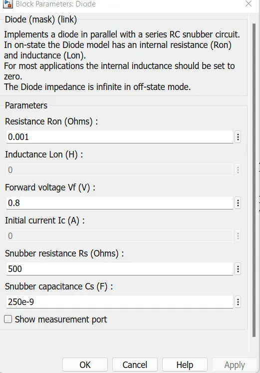
Diode:- Implements a diode in parallel with a series RC snubber circuit. In on-state, the Diode model has an internal resistance (Ron) and inductance (Lon). For most applications, the internal inductance should be set to zero. The Diode impedance is infinite in off-state mode.
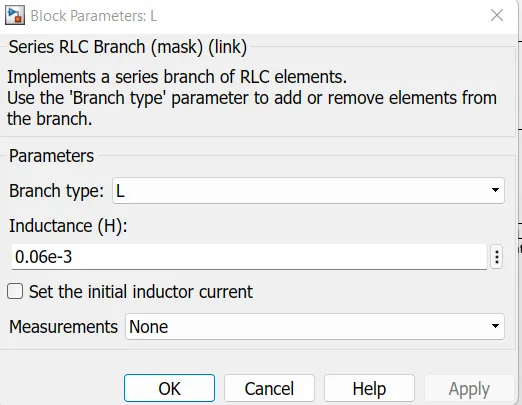
- Inductor:- Use the 'Branch type' parameter to add or remove elements from the branch.
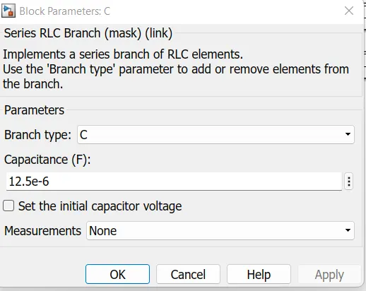
- Capacitor:- a symbol of a capacitor this block is used for the storage of the electric energy for providing Output voltage when required.
- Scope block:- The Simulink Scope block and DSP System Toolbox Time Scope block display time domain signals.
- Control unit- We use the pulse generator as Control unit. Control unit parameter input is given through duty cycle.
- Display block:- This block uses the display of the Output value of Voltage, Current & input volltage.
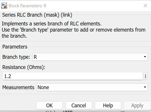
- Load Resistor- Across it we can measure the output voltage & current through it.
Mathematical Formulae-
- Output Voltage = Load resistor * Load current
- Vout = R * iL
- Load Resistor = Output Voltage / Load current
- %Duty ratio D = (Vout / Vin) * 100
- Minimum Inductance Lmin = [(1-D)*Vo] / (deltaI*f)
- Capacitance C = (1-D) / (8*L*r*f^2)
- Ripple factor r = Change in output voltage / rated output voltage
CALCULATIONS:-
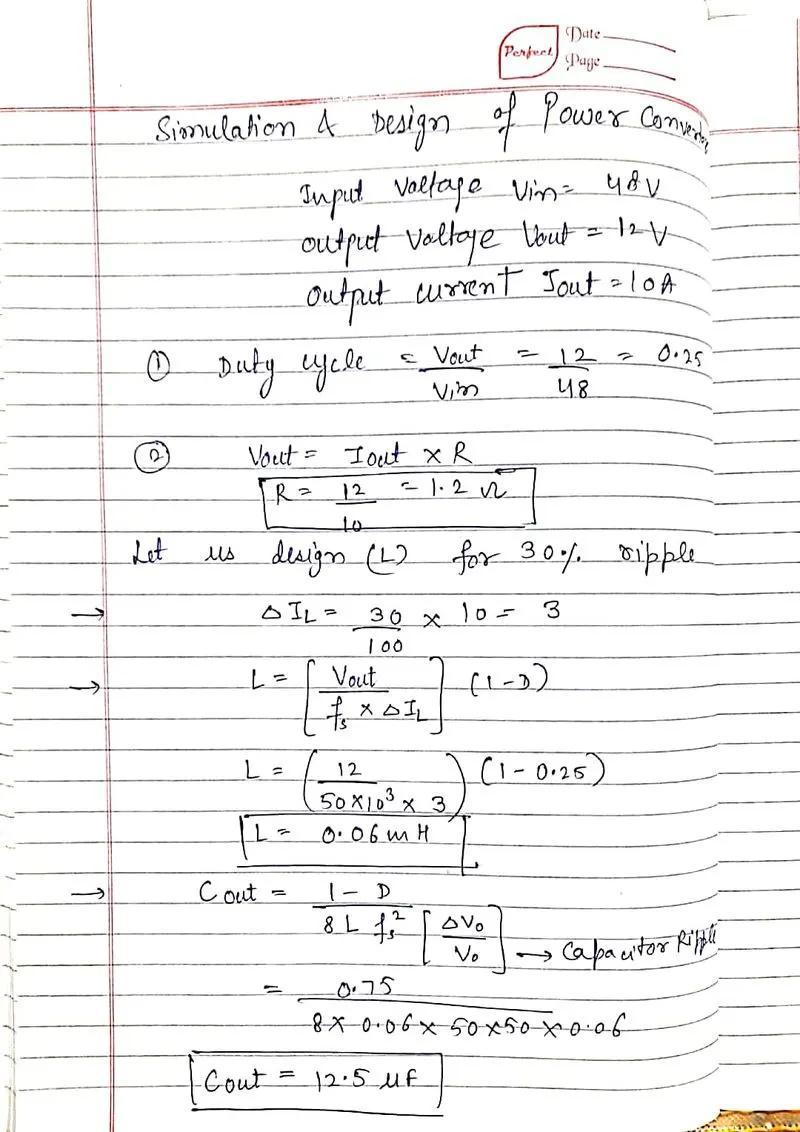
- Load resistor R = Vout / iL = 12/10 = 1.2 ohm.
- Duty ratio(cycle) D = Vout / Vin = 12 / 48 = 0.25
- % D = = 0.25*100 = 25%
- Inductance L = 0.06 mH
- Capacitance C = 12.5 micro farad
SIMULINK MODEL:-
BLOCK PARAMETERS:-
OUTPUT:-
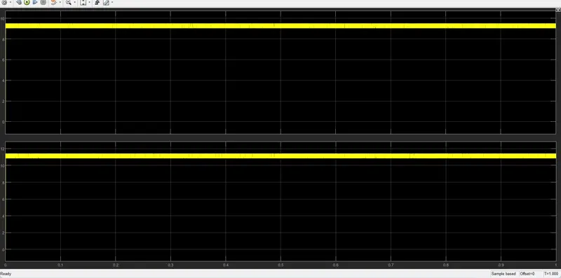
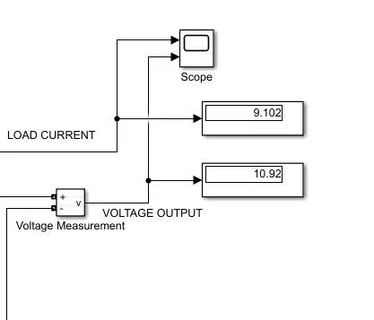
from the waveform & display block we get the required output voltage= 10.92V, Load current=9.102A
CONCLUSION:-
In this project a method is illustrated for Buck converters design in simulation which is based on theorotical calculations first & then computed in simulink environment. When the assume data is vary person to person by referring differnt frequencies & ripple factor then variation may occure in calculation & feeding the data to simulink blocks. I refer the frequency to 50KHz & ripple factor to 30% & do the calculations & build the simulink model with given methods. We do the calculations correctly & the method/steps which i follow provides better accuracy Therefore this technique can be attaractive& effective approach for building buck converter.