Project 1
- PROJECT:- Design and develop a PWM-controlled fan load with DC Moter.
- OBJECTIVE: To model a fan-type load in Simulink and control its speed by using the PWM method.
- THEORY:
- The design of the fan speed control system using Pulse Width Modulation by establishing a connection between an H bridge circuit and a Dc motor.
- A fan type load equation has been used to analyze the output results instead of a physical model of a fan in Simulink. The speed of the fan is varied according to the input voltage using PWM technique.
- By changing or modulating the timing of these pulses the speed of the motor can be controlled. A stepwise change in the speed variation is given and the full load speed is observed.
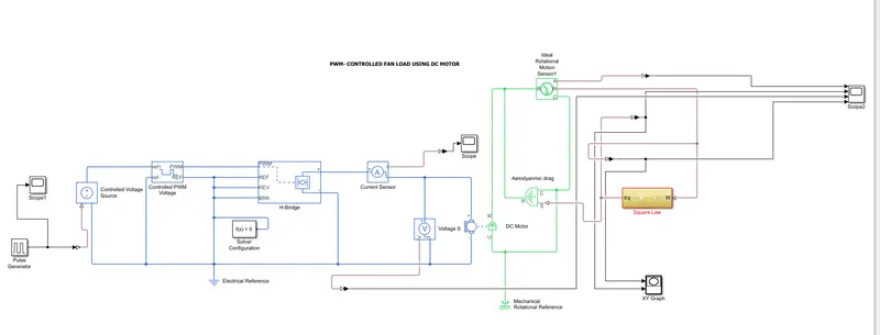
- In this model, all input ports of the H-Bridge block except the PWM port are connected to ground.When the motor is on, the H-Bridge block connects the motor terminals to the power supply.When the motor is off, the H-Bridge block acts as a freewheeling diode to maintain the motor current.
- Pulse-width modulation (PWM) is a powerful technique for controlling analog circuits with a microcontroller's digital outputs. PWM is used in many applications, ranging from communications to power control and conversion.Pulse width modulation turns a digital signal into an analog signal by changing the timing of how long it stays on and off. The term “duty cycle” is used to describe the percentage or ratio of how long it stays on compared to when it turns off.
- The H-bridges are commonly used for speed control of DC motors in both forward and reverse directions. The construction of H-bridges is mainly based on the power semiconductor.The pair of four IGBTs could be utilized for controlling the speed of a DC motor by varying the input signal of the switches.
- CONTROLLED VOLTAGE SOURCE:This block represents an ideal voltage source that is powerful enough to maintain the specified voltage at its output regardless of the current passing through it The output voltage is V=Vs,where Vs is the numerical value presented at the physical signal port
- CURRENT SENSOR:The Current Sensor block represents an ideal current sensor, that is, a device that converts current measured in any electrical branch into a physical signal proportional to the current.
-
The DC motor consist basically of two parts, the stationary body of the motor called the “Stator” and the inner part which rotates producing the movement called the “Rotor”. For D.C. machines the rotor is commonly termed the “Armature”.
Generally, in small light duty DC motors the stator consists of a pair of fixed permanent magnets producing a uniform and stationary magnetic flux inside the motor giving these types of motors their name of “permanent-magnet direct-current” (PMDC) motors.
The motors armature consists of individual electrical coils connected together in a circular configuration around its metallic body producing a North-Pole then a South-Pole then a North-Pole etc, type of field system configuration.
The current flowing within these rotor coils producing the necessary electromagnetic field. The circular magnetic field produced by the armatures windings produces both north and south poles around the armature which are repelled or attracted by the stator’s permanent magnets producing a rotational movement around the motors central axis.
- MECHANICAL ROTATIONAL RESISTANCE:This block represents a mechanical rotational reference point, that is, a frame or a ground. Use it to connect mechanical rotational ports that are rigidly affixed to the frame (ground).This is actually a mechanical system block
- The Electrical Reference block represents an electrical ground. Electrical conserving ports of all the blocks that are directly connected to ground must be connected to an Electrical Reference block. A model with electrical elements must contain at least one Electrical Reference block.
- IDEAL TORQUE SOURCE:The block represents an ideal source of torque that generates torque at its terminals proportional to the input physical signal. The source is ideal in a sense that it is assumed to be powerful enough to maintain specified torque regardless of the angular velocity at source terminals.
- IDEAL ROTATIONAL MOTION SENSOR:Ideal motion sensor is provide here to sense the rotational speed of the motor.
-
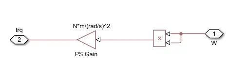
SQUARE LAW SUBSYSTEM: It is a combination of PS product and PS gain block.
-
Torque exerted by fan represented by TL
Load torque i.e. TL proportional to square of speed i.e. wm^2
TL = C . wm^2
By varying the electrical parameter of motor i.e. voltage and current we are controlling load torque or load speed.
For fan load we don’t have any block to represent a fan so we are representing by a subsystem
-
Then gain block is used that is the constant of proportionality 8.8e-8 Unit of this gain block is N*m/(rad/s)^2
Output of this subsystem is fed to the Aerodynamic block. Actual name of this block is Ideal torque source block. This ideal torque source block is going to apply torque on the shaft of DC motor.
-
Working:
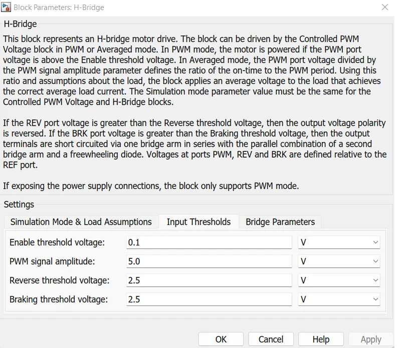
The signal from the pulse generator is given to physically controlled voltage source,It produces voltage output according to the physical signal input,these output are also varies between zero to 1The output of controlled voltage source1 goes to controlled PWM .It give output according to input signalsThese output values is fed to a H bridge If the input signal has a value greater than the Enable threshold voltage parameter value 2.5V the H-Bridge block output is on and has a value equal to the value of the Output voltage amplitude 800V. If it has a value less than the Enable threshold voltage parameter value, the block maintains the load circuit using freewheeling diode.The Output of H bridge is connected to dc motor the motor rotates according to the voltage output fom h bridge.This speed of the motor is sensed by ideal rotational motion sensor and taken as output ,by using square law Torque also calculated.
- Model Diagram in Simulink:-
-
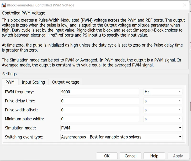
Parameter needs to update.
In PWM voltage block set PWM frequency as 4000 Hz
- H-Bridge parameters:
-
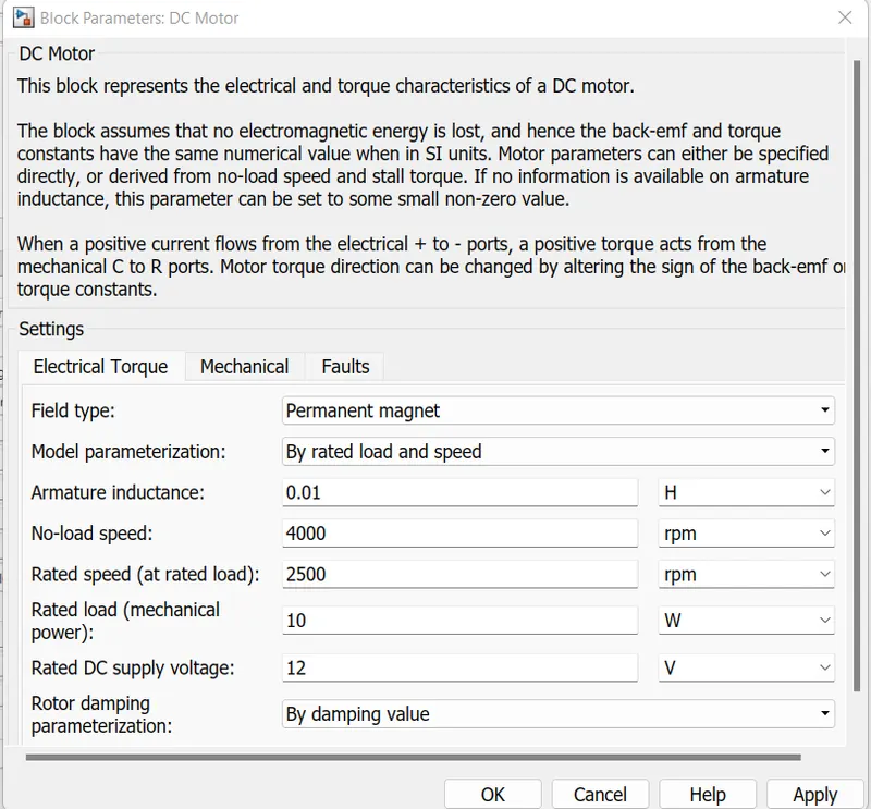
Dc motor configuration :
-
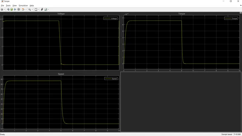
Output result of scope:
-
Conclusion:Simulation of PWM controlled dc motor fan load is done and Output are observed.