Project 3
Aim : Design and simulation of Buck converter for Auxiliary load in EV.
- Input voltage is 48V, Output voltage is 12 V
- Load current is 10A
Objective :
- Calculate Duty ratio and Load(use Resistor as Load)
- Calculate L,C
Introduction :
Buck converter:-
- A buck converter (step-down converter) is a DC to DC power converter which steps down voltage - often creating 5V DC from perhaps a 12 or 24V DC source.
- Switching converters (such as buck converters) provide much greater power efficiency. as DC-to-DC converters than linear regulates, which are simpler circuits that lower voltages by dissipating power as heat, but do not step up output current.
- Used to run some auxillary equipment in EV like headlight, horn, indicators etc.
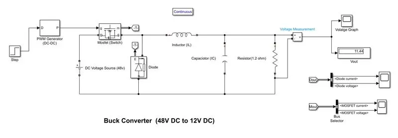
Simulink model of BUCK Converter :
Main Block used:-
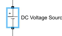
DC Voltage source:- This block is used here for the Input providing 48V. The DC Voltage Source block represents a constant voltage source whose output voltage value is independent of the current through the source.
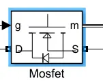
MOSFET:- MOSFET and internal diode in parallel with a series RC snubber circuit. When a gate signal is applied the MOSFET conducts and acts as a resistance (Ron) in both directions. If the gate signal falls to zero when the current is negative, the current is transferred to the antiparallel diode.
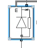
Diode:-
Implements a diode in parallel with a series RC snubber circuit. In on-state, the Diode model has an internal resistance (Ron) and inductance (Lon). For most applications, the internal inductance should be set to zero. The Diode impedance is infinite in off-state mode.
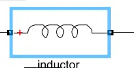
Inductor:- Use the 'Branch type' parameter to add or remove elements from the branch.
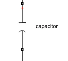
Capacitor:- a symbol of a capacitor this block is used for the storage of the electric energy for providing Output voltage when required.
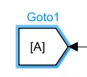
GOTO block:- Send signals to From blocks that have the specified tag. If tag visibility is 'scoped', then a Goto Tag Visibility block must be used to define the visibility of the tag. The block icon displays the selected tag name (local tags are enclosed in brackets, [], and scoped tag names are enclosed in braces, {})
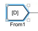
From block:- Receive signals from the Goto block with the specified tag. If the tag is defined as 'scoped' in the Goto block, then a Goto Tag Visibility block must be used to define the visibility of the tag.
Scope block:- The Simulink Scope block and DSP System Toolbox Time Scope block display time domain signals.
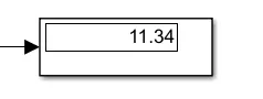
Display block:- This block uses the display of the Output value
- Step signal is used as input to PWM Dc- Dc converter.
- Then the output is fed as input to the MOSFET block which is acts as a switch and resistor.
- DC voltage source is used to take supply 48 volt dc signal to mosfet which further convert this signal to 12 volt dc
- Before running the simulation we need to calculate the values for L and C components.
Calculations -
Duty ratio(D): It is nothing but the ratio of the input voltage source to Output voltage is known as duty ratio its formula is shown below and find out the value.
duty ratio (D) = Vo/Vs
= 12/48
= 1/4
=0.25
Inductor(L): We know that calculating inductor from its formula is given by
L= (1-D)(R)/2f
=(1-0.25)(10)/2*50
=7.5/100
= 0.075 uf
Capacitor(C):
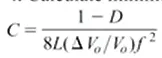
=1-0.25/8*0.075(0.005)50*50
=0.1uf
Result :
1) The final output plot of Buck Converter is shown below, the final output voltage is 11.34 volt
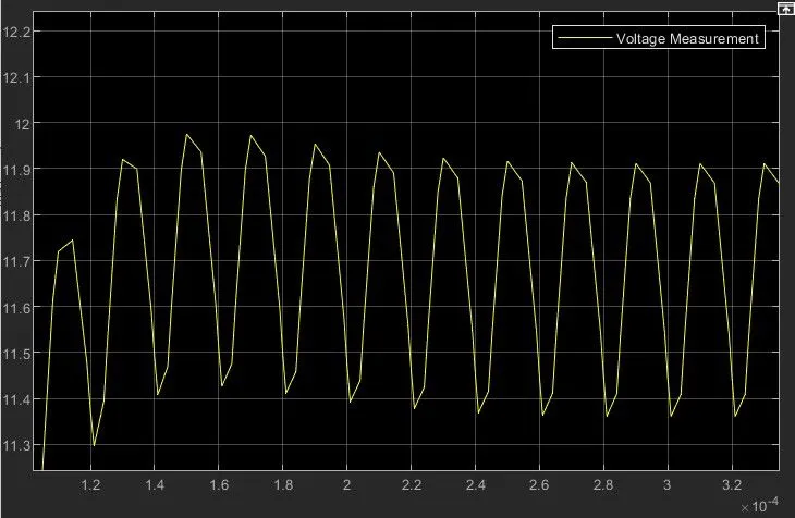
2) Plot for MOSFET output voltage & current
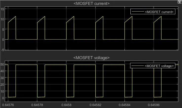
Conclusion:
- Simulation is done using the buck converter in which information is given and also calculated the value of the capacitor = 0.1uf, inductor = 0.075uf and duty ratio = 0.25.
- After running the buck converter simulation the output result we can observed is 11.34 volt