Project 3
PROJECT 3:-
Design and simulation of Buck converter for Auxiliary load in EV.
- The input voltage is 48V, the Output voltage is 12 V
- The load current is 10A
- Calculate Duty ratio and Load(use Resistor as Load)
- Calculate L, C
SOLUTION:-
Buck converter:-
A buck converter (step-down converter) is a DC to DC power converter which steps down voltage - often creating 5V DC from perhaps a 12 or 24V DC source.
Switching converters (such as buck converters) provide much greater power efficiency. as DC-to-DC converters than linear regulates, which are simpler circuits that lower voltages by dissipating power as heat, but do not step up output current.
The efficiency of buck converters can be very high, often over 90%, making them useful for tasks such as converting a computer's main supply voltage, which is usually 12 V, down to lower voltages needed by USB, DRAM, and the CPU, which are usually 5, 3.3 or 1.8 V.
Given condition:-
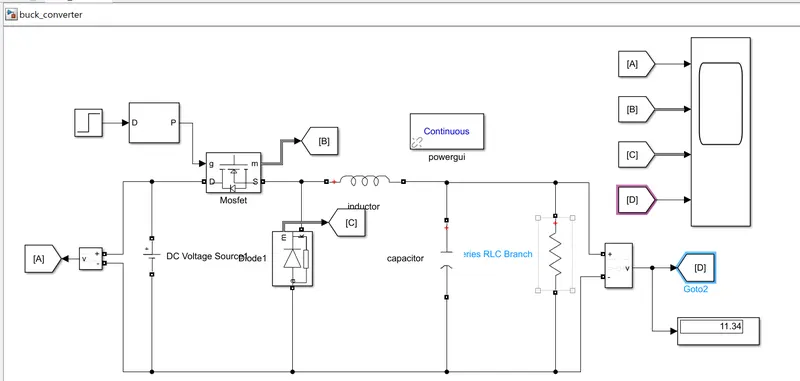
- The input voltage is 48V, the Output voltage is 12 V, and runs the simulation and finds the output shown below.
Simulink Model:-
Main Block used:-
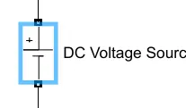
DC Voltage source:- This block is used here for the Input providing 48V. The DC Voltage Source block represents a constant voltage source whose output voltage value is independent of the current through the source.
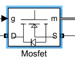
MOSFET:- MOSFET and internal diode in parallel with a series RC snubber circuit. When a gate signal is applied the MOSFET conducts and acts as a resistance (Ron) in both directions. If the gate signal falls to zero when the current is negative, the current is transferred to the antiparallel diode.
Diode:-
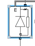
Implements a diode in parallel with a series RC snubber circuit. In on-state, the Diode model has an internal resistance (Ron) and inductance (Lon). For most applications, the internal inductance should be set to zero. The Diode impedance is infinite in off-state mode.
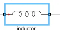
Inductor:- Use the 'Branch type' parameter to add or remove elements from the branch.
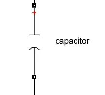
Capacitor:- a symbol of a capacitor this block is used for the storage of the electric energy for providing Output voltage when required.
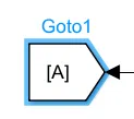
GOTO block:- Send signals to From blocks that have the specified tag. If tag visibility is 'scoped', then a Goto Tag Visibility block must be used to define the visibility of the tag. The block icon displays the selected tag name (local tags are enclosed in brackets, [], and scoped tag names are enclosed in braces, {})
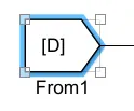
From block:- Receive signals from the Goto block with the specified tag. If the tag is defined as 'scoped' in the Goto block, then a Goto Tag Visibility block must be used to define the visibility of the tag.
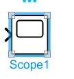
Scope block:- The Simulink Scope block and DSP System Toolbox Time Scope block display time domain signals.
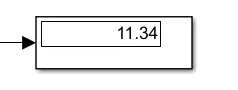
Display block:- This block uses the display of the Output value
Calculation:
- Calculate Duty ratio and Load(use Resistor as Load)
- Calculate L, C
Duty ratio(D): It is nothing but the ratio of the input voltage source to Output voltage is known as duty ratio its formula is shown below and find out the value.
duty ratio (D) = Vo/Vs
= 12/48
= 1/4
=0.25
Inductor(L): We know that calculating inductor from its formula is given by
L= (1-D)(R)/2f
=(1-0.25)(10)/2*50
=7.5/100
= 0.075 
Capacitor(C):
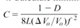
=1-0.25/8*0.075(0.005)50*50
=0.1 
Conclusion:
In this project, simulation Is done using the buck converter in which information is given and also calculated the value of the capacitor, inductor, and duty ratio