Project
*AIM:- To study the system-level simulation of an all-terrain vehicle.
*OBJECTIVE:-
Carry out a system-level simulation of an all-terrain vehicle and prepare a technical report explaining the model properties and comments on the result.
*ANSWER:-
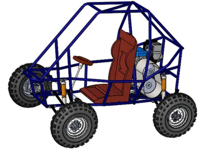
All-terrain vehicle:-
An all-terrain vehicle ATV a defined as a motored off-highway vehicle designed to travel on four low pressure or non-pneumatic tires, having a seat designed to be straddled b the operator and handlebar for steering control.
*Major Block Used In Simulation:-
>Generic Engine:- The generic block represent a general internal combustion engine. which is a type of spar ignition(petrol) or compression ignition(CI Diesel). The speed torque and speed power parameters are provided.
>Simple Gear:- The simple gear is a combination of a driven rear where the speed is reduced by the gear ratio. the gear ratio is defined as.
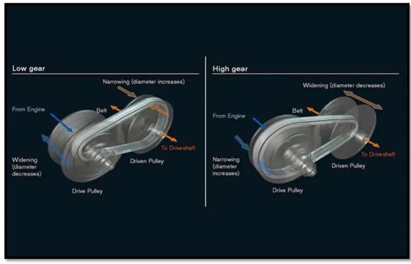
>CVT Transmission:- In CVT(continuous variable transmission) the variable diameter pulley plays a vital role in transmission variable diameter pulleys must always come in pairs one of the pulleys. Known as the drive pully, is connected to the crankshaft of the engine. The driving pulley is also called the input pulley because its where the energy from the engine enters the transmission. The second pulley is called the driven pulley because the first pulley is turning it as an output pulley the driven pulley transfers energy to the driveshaft.
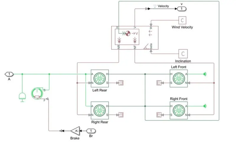
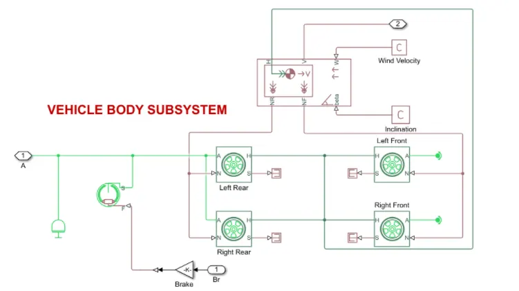
>Vehicle Body:- Two axle vehicles with longitudinal dynamics and motion and adjustable mass, geometry, and drag properties, the vehicle can have the same or a different no. of wheels on each axle. for example, two wheels on the front axle and one wheel on the rear axel the vehicle wheels are assumed identical in size the vehicle can also have a center of gravity that is at or below the plane of travel.
>Double Shoe Brake:- The double shoe brake block represents a frictional brake with two pivoted rigid shoes that press against a rotating drum to produce a braking action. The rigid shoe si inside or outside the rotation drum in a diametrically opposed configuration. A positive actuation force caused the rigid shoes to press against the rotation drum. Viscous and contact friction between the drum and the rigid shoe surfaces cause the rotation drum to decelerate.
>Tire:- The vehicle body is connected to 4 tires each per axle to move the vehicle according to the power input to the axle.
*Block used:-
- Signal builder - To input the Brake, throttle, and CVT Ration.
- Simulink to PS converter - To convert the Simulink signal to the simscape environment.
- Solver Configuration - To specify the solver parameters before starting the simulation.
- Mechanical Reference - To make sure all the components are clamped to the ground.
- Inertia - To represent the solid inertia.
- Rotation Motion Sensor - To see the rotational motion from the engine and give output as RPM.
- Variable Gear Ratio - To vary the speed according to the gear ratio.
- PS Terminator - Terminator for unconnected physical signal outputs.
- PS Constant - Generate constant physical signal
- Rotational Free End - For mechanical component (Tire).
- Custom Measure Gauge - To measure the brake and throttle input.
- Knob - To increase, decrease, and vice-versa of throttle and brake inputs.
- Lookup Table - To insert the CVT values from the workspace.
- Step - To increase or decrease an input value for a defined time interval.
*Types of Model:-
1. Baja ATV Model Without A Dashboard.
2. Baja ATV Model With A Dashboard.
3. Baja ATV Model Using Lookup Table Without A Dashboard.
4. Baja ATV Model Using Lookup Table With Dashboard.
*1. Baja ATV Model Without A Dashboard:-
BAJA ATV MODEL WITHOUT DASHBOARD
*Main Model:-
CVT SYSTEM
VEHILE BODY
*Simulation Process:-
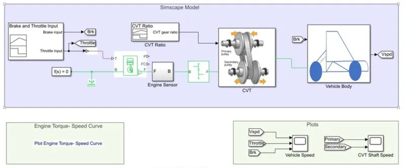
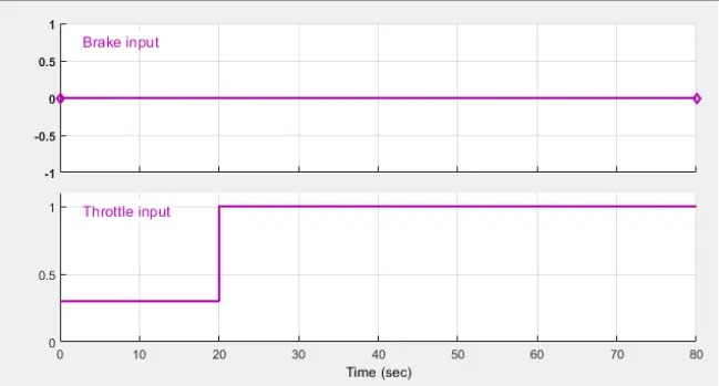
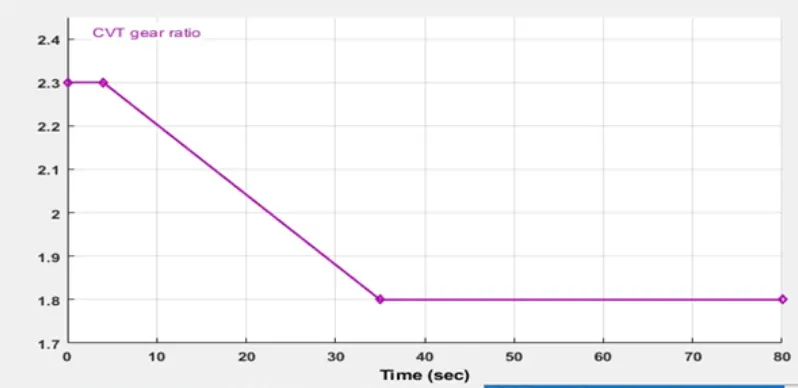
The signal builder is used as input for brake, throttle, and gear ratio. Brake input is maintained as O for overall simulation. The throttle input is given and increases to 1 for the overall simulation. The throttle valve is mainly to control the flow or amount of fuel into the engine if the throttle value increases the flow of fuel increases to the IC engine which in turn increases the power of the engine. The gear ratio is maintained and linearly decreases and maintained constant for overall simulation as shown in the above.
*Input signal:-
for CVT gear ratio
*Output Signal:- VELOCITY AND SHAFT SPEED
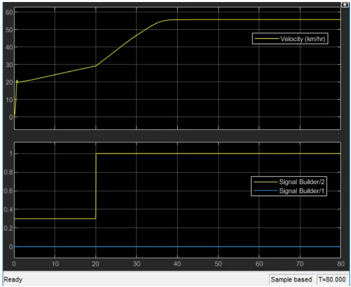
In the above figure, the brake is maintained as constant and increased throttle which shows an increase in velocity. The flow of fuel increases when the throttle increases from 0.3 to 1, thus the power in the engine increase. The torque reaches approximately 7N-m at a 1.8 gear ratio. which defines that gear ratio is directly proportional to the torque by this gear ratio, the speed and velocity can achieve maximum.
CVT SHAFT RPM
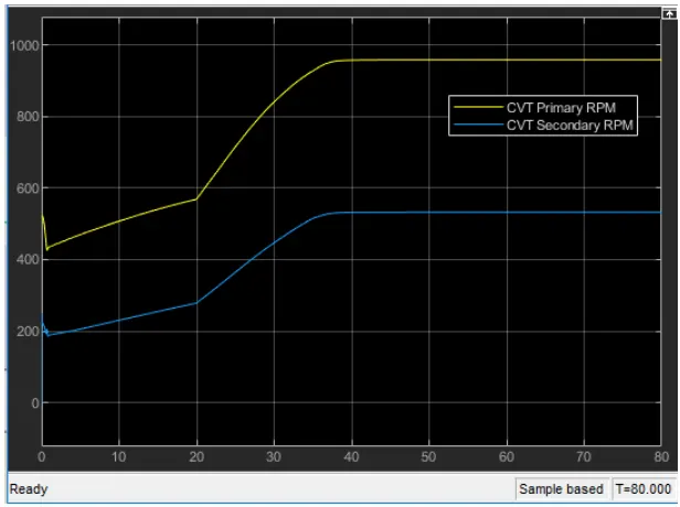
In the above figure, the primary shaft reaches high speed and the secondary shaft as low rotational speed because of the radius of the primary shaft is more than the secondary shaft. the speed is directly proportional to the radius of the shaft. As the radius increases the speed of the shaft also increases.
*2. Baja ATV Model With Dashboard:-
BAJA ATV MODEL WITH DASHBOARD
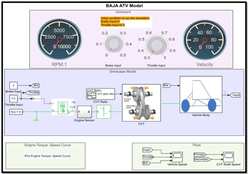
In this model Baja ATV with dashboard model which consists of throttle meter and brake input in the dashboard instead of giving input through a signal builder. The rest of the blocks and subsystems are common in the above Baja ATV model without a dashboard. The main concept of using a dashboard is to study the result by varying the input of the brake and throttle. which shows that the velocity and speed of the engine. By increasing the throttle. the velocity and speed of the engine and shaft increases.
*Output signal:- VELOCITY AND SHAFT SPEED
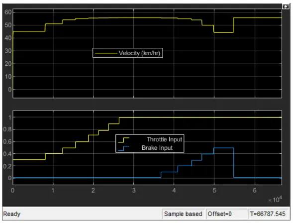
The velocity of the vehicle is maintained as constant for constant throttle value as 0.3 and varying by increasing the value of throttle which increases the velocity of the vehicle. By increasing the brake input. the velocity of the vehicle decreasing accordingly.
CVT SHAFT RPM
*3. Baja ATV Model Using lookup Table without Dashboard:-
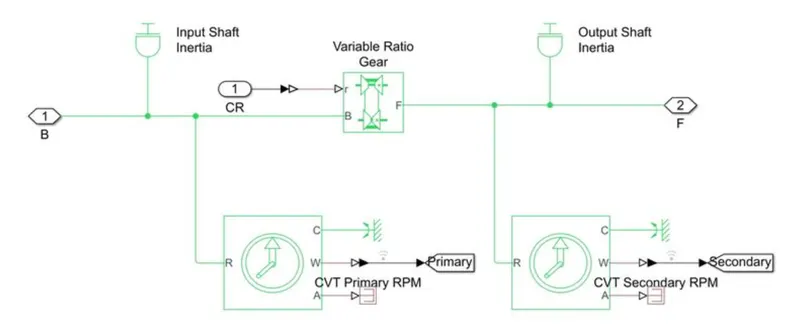
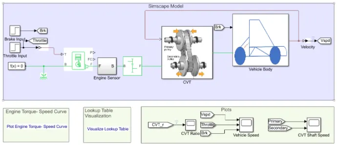
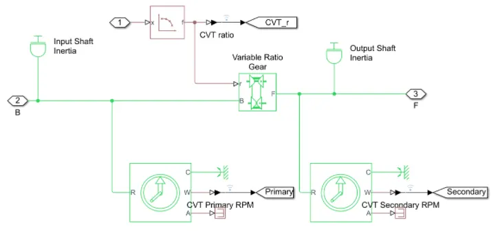
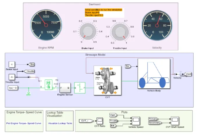
By using the Simulink model of CVT consists of step time. generic engine. motion sensor, vehicle transmission, vehicle body, tires and solver configuration blocks, etc. The CVT subsystem includes a look-up table, transmission block. input and output shaft inertia and motion sensors as shown above. The vehicle body subsystem includes a vehicle body block. double drum brake and tires.
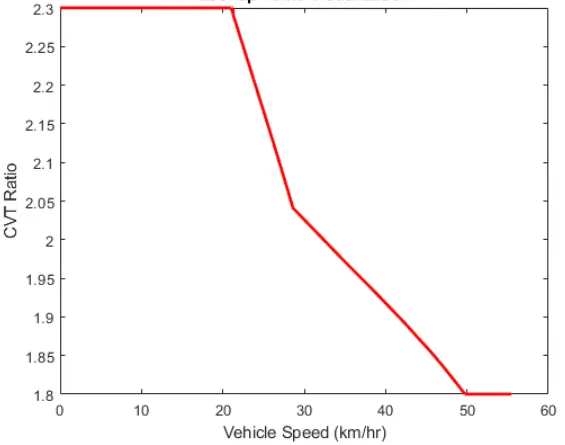
A lookup table is an array of data that maps input values to output values, thereby approximating a mathematical function. Given a set of input values, a lookup operation retrieves the corresponding output values from the table. if the lookup table does not explicitly define the input values, Simulink can estimate an out value using interpolation, extrapolation rounding
BAJA ATV MODEL USING LOOKUP CHART
CVT SYSTEM
The brake input and throttle are given by step time, which depends on the run time and varies accordingly. By using a lookup table for ear ratio which takes as input to the CVT and works according to the input gear ratio and obtained the output. This method is very effective which can avoid the unusual torque at a certain speed and very easy to achieve greater velocity and engine speed. It works as a closed-loop when the input is given by the lookup table, The Simulink gets the input value from a lookup table and obtains the result according to the input values of gear ratio. The gear ratio varies from2.3 to1.8 as taken as input and output in terms of velocity. The maximum velocity reached was 57 km approximately.
LOOKUP TABLE
*Output signal:- VELOCITY AND SHAFT SPEED
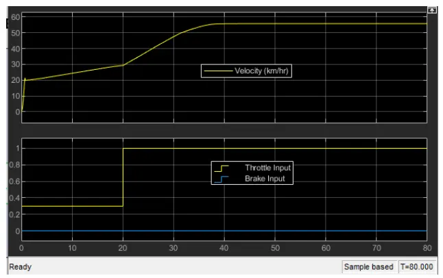
The brake in maintained as constant and increase in throttle which showed an increase in velocity. The flow of fuel increases when the throttle increases from 0.3 to 1, thus the power in the engine increases. The torque reaches approximately 7N-m at a 1.8 gear ratio. which defines that the gear ratio is directly proportional to the torque. By this gear ratio. the speed and velocity can achieve maximum, The gear ratio is assigned in the lookup table and given as input to the Simulink which reads every input value and option the result according to the input.
CVT SHAFT SYSTEM
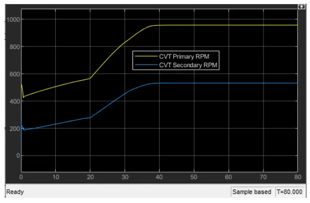
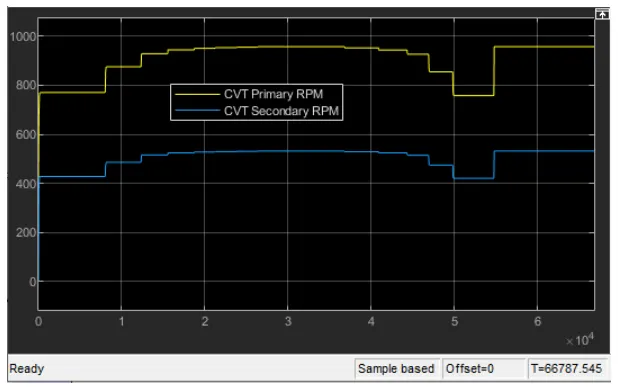
The primary shaft speed increases by increasing throttle and decreasing by increasing brake input value, which defines that the throttle can flow moe amount of fuel which increases the power of the engine and is similar to the secondary shaft. The radius of the primary shaft as more than the secondary shaft, the speed is directly proportional to the radius of the shaft, As the radius increase, the speed of the shaft also increases.
*4. Baja ATV Model Using Lookup Table With the Dashboard:-
The Baja ATV with dashboard model using lookup Table which consists throttle meer and brake input in the dashboard and indicated as a constant block. The rest of the blocks and subsystems are common in the above Baja ATV model without a dashboard. The main concept of using the dashboard as study the result by varying the input of brake and throttle which shows that the variation of velocity and speed of the engine. The gear ratio s given by the lookup table. Simulink gets the input value from the lookup table and obtains the gear ratio also decreasing by increasing the throttle. the velocity and speed of the engine and shaft increases. The transmission is a primary pulley and secondary pulley. in which the radius of the primary pulley increases by compacting and the radius of the secondary pulley decreases. As the gear ratio varies. the torque also varies. The gear ratio is directly proportional to the torque, which increases by increasing the gear ratio. At the max torque, the speed and velocity is decreased.
BAJA ATV MODEL USING LOOKUP TABLE WITH THE DASHBOARD
*Output signal:- VELOCITY AND SHAFT SPEED
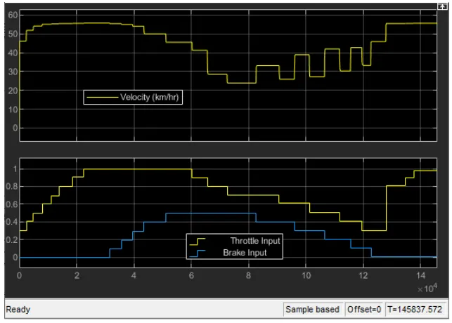
The velocity of the vehicle is maintained as constant for constant throttle value as 0.3 and varying by increasing the value of throttle which increases the velocity of the vehicle. By increasing the brake input, the velocity of the vehicle decreases accordingly to a random value within the range by using extrapolation and interpolation by lookup table.
CVT SHAFT SYSTEM
The primary shaft speed increases by increasing throttle and decreasing by increasing brake input value. which defines that the throttle can flow more amount of fuel which increases the power of the engine and is similar to the secondary shaft. The radius of the primary shaft as more than the secondary shaft, the speed is directly proportional to the radius of the shaft. As the radius increases the speed of the shaft also increases the throttle value and brake input value can be varying in the dashboard, so we can get any particular value for the input.
*CONCLUSION:-
- As the throttle increase, the velocity also increases which in turn the power in the engine also increases. In the beginning, the speed was reduced because of the gear ratio and torque output. When the gear ratio increase. the torque increases.
- As the brake input increases, the velocity decreases, and engine power also decreases. At a certain brake input value, the engine may shut down and there is no power output. the engine power is inversely proportional to the brake input.
- As the gear ratio increases, torque increases which in turn velocity decreases. The torque is increasing by an increase in engine speed. At a particular point, the torque is decreasing when the gear ratio increases in order to achieve maximum velocity.
- With help of a lookup table, we can vary any input value and also get the output value by using interpolation and extrapolation method which the symlink can solve.