Week -2
AIM:-
I. To make a Simulink model of doorbell using Solenoid Block.
II. To use the thermistor to sense the temperature of heater and turn ON or turn OFF the fan.
PART I.
*THEORY:-
*Solenoid:-
It transfers electrical energy into kinetic energy. A Solenoid is a device comprised of a coil of wire housing and a moveable plunger (armature). When an electrical current is induced. A magnetic field forms around the coil which draw the plunger in simple a solenoid converts electrical energy into mechanical work.
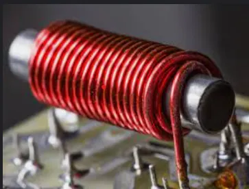
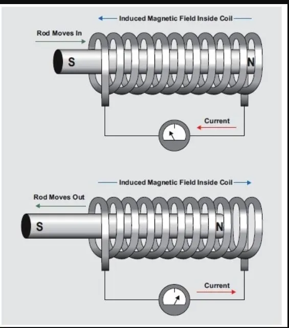
Figure(1.1):- Construction of Solenoid.
*Doorbell:-
The doorbell mainly works on the principle of electromagnetism. Electromagnets are coils of wire wrapped around a small piece of magnet metal. When electricity passes through the wire, it creates a magnetic field around the wire. When the switch is ON, the circuit becomes active and the solenoid activates the plunger that creates the doorbell sound.
*SIMULINK MODEL FOR DOORBELL:-
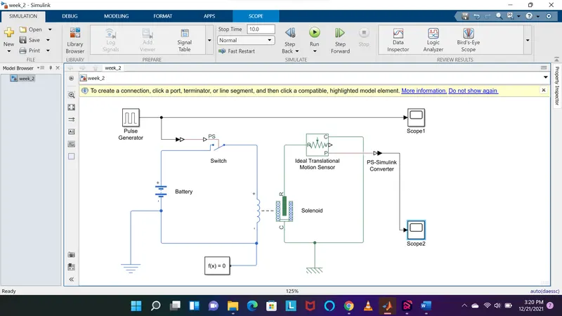
Figure(1.2):- Simulink Model of Doorbell Using Solenoid Block.
*Simulink Model Explanation:-
- Pulse Generator:- This block generates square wave pulses at regular intervals. The block waveform parameters, Amplitude, Pulse, Width, Period, and phase delay. Determine the shape of the output waveform
- Simulink-PS Converter:- It converts the Simulink input signal into a physical signal.
- Switch:- This block is controlled by an external physical signal.
- Battery:- It gives the power to the close loop.
- Electrical Reference:- It shows the connection to electrical ground.
- Ideal Translational Motion Sensor:- It is a motion sensor in a mechanical translational system.
- Solenoid:- The solenoid block represents the electrical characteristics and generated force.
- PS-Simulink Converter:- It converts the physical signal into a Simulink output signal.
- Mechanical Translational Reference:- Reference connection for mechanical translational ports.
- Scope:- It displays signal generated during simulation.
*Input Signal:-
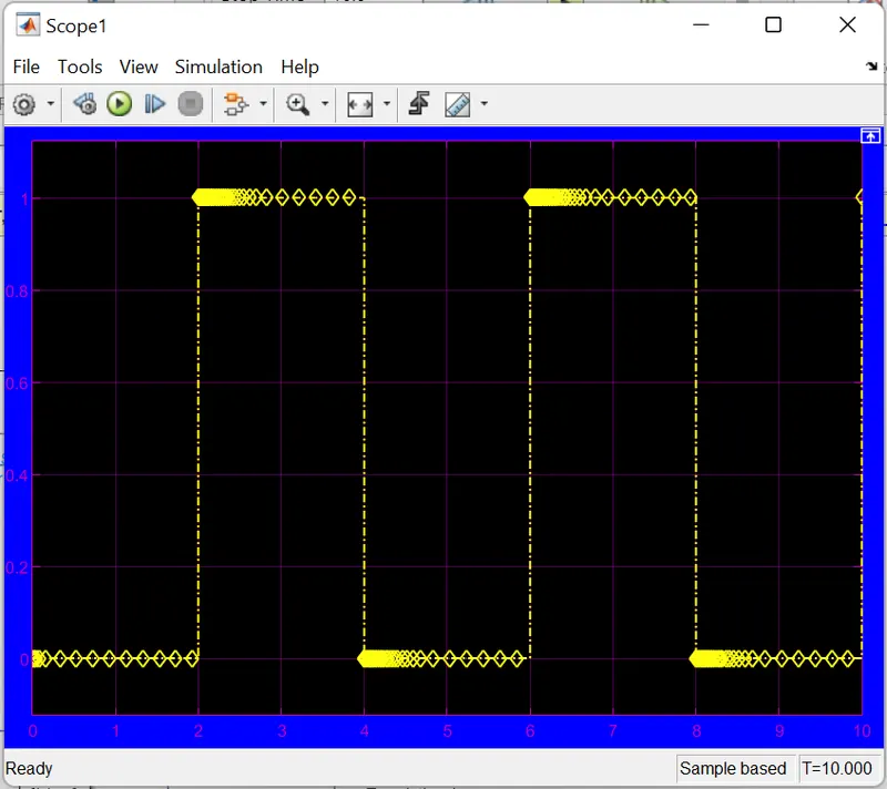
Figure(1.3):- Input Signal.
*Output Signal:-
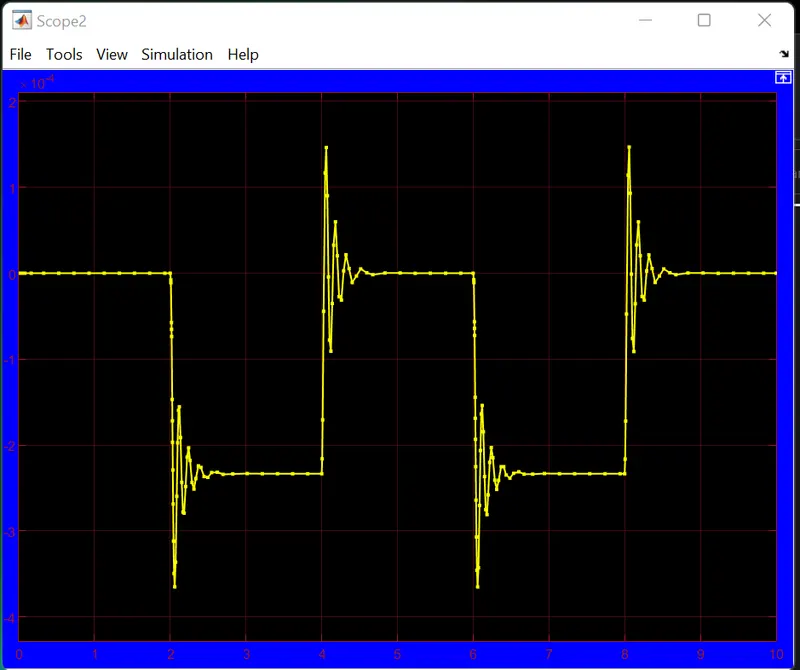
Figure(1.4):- Output Signal.
*RESULT:-
- In the above result, the switch is closed the electromagnet receives electrical power from the battery and pulls the lever, ideal translational motion sensor sense that movement and gives the output by scope.
PART II.
*THEORY:-
*Thermistor:-
It is a type of resistor in which the flow of electric current changes rapidly with a small change in temperature.
Thermistors derived from the term thermally sensitive resistors are a very accurate and cost-effective sensor for measuring temperature available in 2 types. NTC (Negative temperature coefficient) and PTC (Positive temperature coefficient). It is the NTC thermistor that is commonly used to measure temperature.
A thermistor is a resistance thermometer or a resistor whose resistance is dependent on temperature. The term is a combination of "thermal" and "resistor. It is made of metallic oxides, pressed into a bead, disk, or cylindrical shape and then encapsulated with an impermeable material such as epoxy or glass.
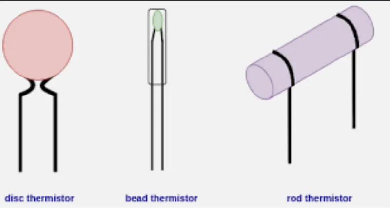
Figure(2.1):- Different form of construction of thermistor.
*SIMULINK MODEL OF THERMISTOR:-
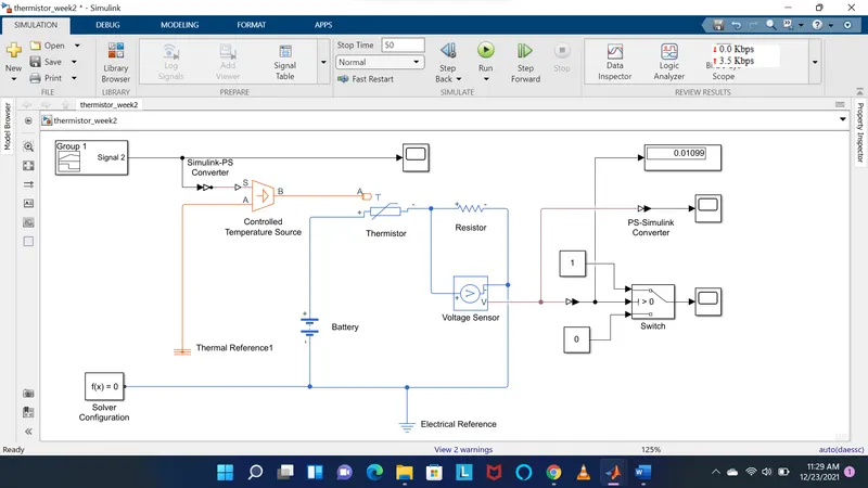
Figure(2.2):- Simulink Model for Fan Controlled By Thermistor.
*SIMULINK MODEL EXPLANATION:-
- Signal Builder:- It is used to input the values as per the given condition.
| Sr. no. | At position | Time(second) | Temperature(kelvin) |
| 1 | At point 1 | 0 | 293 |
| 2 | At point 2 | 10 | 293 |
| 3 | At point 3 | 10 | 300 |
| 4 | At point 4 | 30 | 300 |
| 5 | At point 5 | 30 | 296 |
| 6 | At point 6 | 50 | 296 |
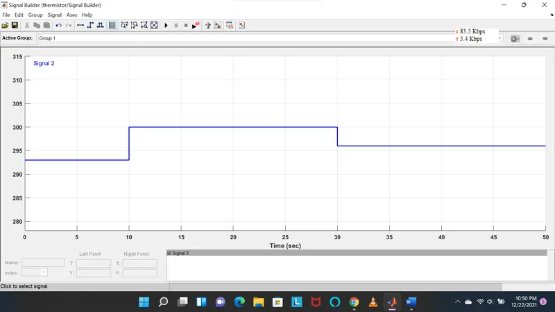
Figure(2.3):- Signal Builder Block.
- Controlled Temperature Source:-
This block represents an ideal source of thermal energy that is powerful enough to maintain specified temperatures difference across the sources regardless of the heat flow consumed by the system. Connection A and B are thermal conserving ports corresponding to the source inlet and outlet respectively. Port S is a physical signal port, through which the control signal that drives the source is applied.
- Resistor:- The resistor block models a linear resistor described with the following equation.
V=IR
Where, V=Voltage
I=current
R=resistance
- Voltage Sensor:-
It is used to convert the voltage measured between two points of an electrical circuit into a physical signal proportional to the voltage.
- Voltage Source:- The block implements a voltage source with DC, AC, and noise components.
- Electrical Reference:-
The block represents an electrical ground. Electrical conserving ports of all the directly connected blocks to the ground must be connected to an Electrical Reference Block. A model with electrical elements must contain at least one Electrical Reference block.
*Input Waveform:-
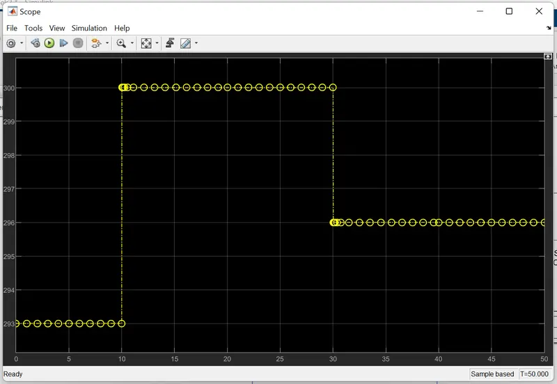
Figure(2.4):- Input Waveform.
*Output Waveform:-
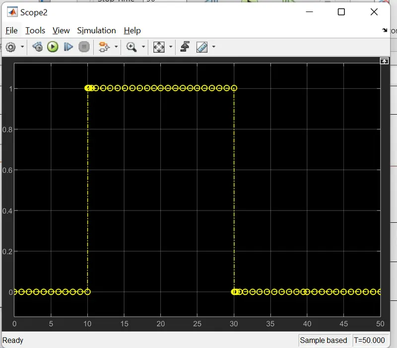
Figure(2.5):- Output Waveform.
*Result:-
(Fan condition. ON if the temperature is above 25°C. OFF otherwise)
- A thermistor is used to sense the temperature of a heater and turn on or turn off the fan as per the above conditions.
- Therefore the fan conditions are executed by switch block and plotted in scope block.