Thermal modeling of battery pack project 2
AIM:
For a 10 cell series lithium ion battery model, to simulate the thermal effects and compare life cycle performance at various temperatures, charge & discharge rates using MATLAB.
THEORY:
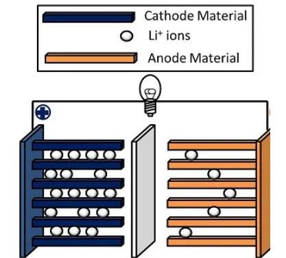
A lithium-ion (Li-ion) battery is an advanced battery technology that uses lithium ions as a key component of its electrochemistry. During a discharge cycle, lithium atoms in the anode are ionized and separated from their electrons. The lithium ions move from the anode and pass through the electrolyte until they reach the cathode, where they recombine with their electrons and electrically neutralize. The lithium ions are small enough to be able to move through a micro-permeable separator between the anode and cathode. In part because of lithium’s small size (third only to hydrogen and helium), Li-ion batteries are capable of having a very high voltage and charge storage per unit mass and unit volume.
Li-ion batteries can use a number of different materials as electrodes. The most common combination is that of lithium cobalt oxide (cathode) and graphite (anode), which is most commonly found in portable electronic devices such as cellphones and laptops. Other cathode materials include lithium manganese oxide (used in hybrid electric and electric automobiles) and lithium iron phosphate. Li-ion batteries typically use ether (a class of organic compounds) as an electrolyte.
A built in matlab model " lithium-ion battery pack with fault " is shown below.

as we can see in the model , the 20 lithium ion cells are connected in series.
the 10 th cell in the battery pack is considered as faulty.
the faulty cell means that the temperature of that particular cell is not maintained properly and thus this faulty cell will effects the performance of overall battery pack.
A fault can be introduced into one of the cells to see the impact on battery performance and cell temperatures. For efficiency, identical series-connected cells are not just simply modelled by connecting cell models in series. Instead a single cell is used, and the terminal voltage scaled up by the number of cells.
The fault is represented by changing the parameters for the Cell 10, reducing both capacity and open-circuit voltage, and increasing the resistance values.
now if we open the cell 01 to 09 block,
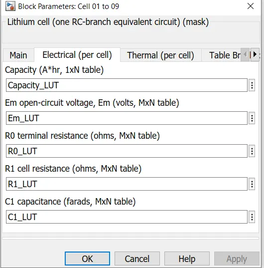
we can see that , the cells is working at its full potential.
now if we open the cell 10 block,
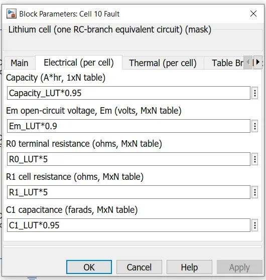
we can see that ,
1) capacity is multipied by 0.95.
thus means that capacity is reduced by 5 %
2) the open circuit voltage is miltipled by 0.9
this means that , the open circuit voltage is reduced by 10%.
3) the cell resistance is multiplied by 5
this means that cell resistance is increased 5 times.
as resistance increases , the temperature of cell also increases.
this all changes are done to show that the cell 10 is in faulty condition.
as we can see in the model,
there is convective heat transfer from battery pack to surrounding environment
and there is conduction heat transfer between the cells of battery pack.
as in the question , it is mentioned that '10 cell series lithium ion battery'
thus we have to make certain changes in the model.
i)
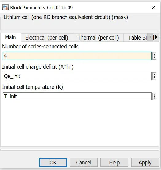
thus change 9 cells to 4 cells
ii)
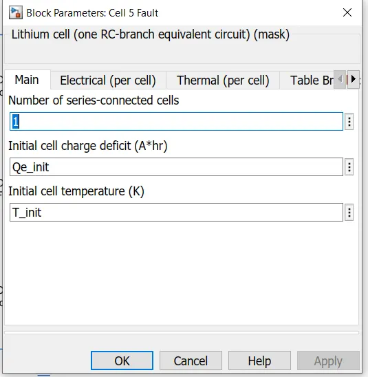
change 10 th cell as 5th cell and let this cell be faulty.
iii)
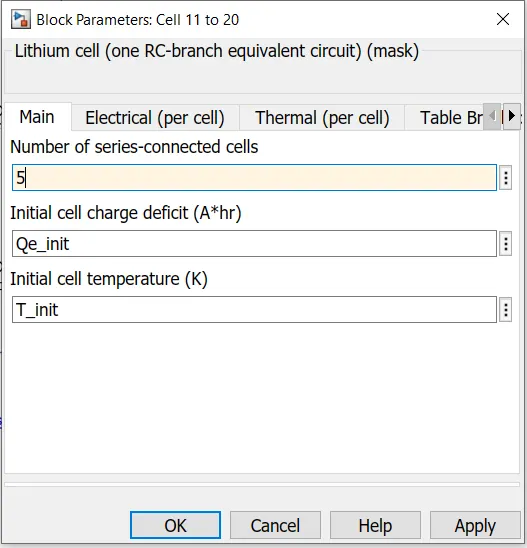
change 10 cell to 5 cell.
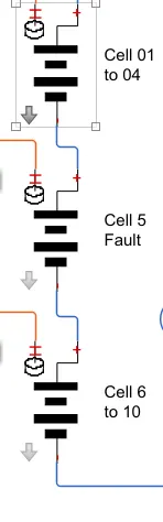
thus we got in total 10 lithium ion cell and 5th cell is faulty.
TO ESTIMATE SOC:
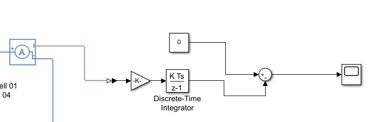
1)current sensor block
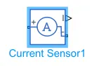
the current sensor block is used in the model.
this current sensor will measure the current through the battery pack.
2) ps-simulink converter

the output of current sensor is given to ps-simulink converter to convert physical signal to simulink format.
3)gain block
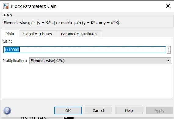
as we are using coulomb counting method, thus gain block is used here.
the value of gain block is set to 1/10000.
4)discrete time integrator block
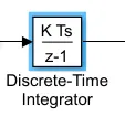
the discrete time integrator block is used to integrate the current flowing through the battery pack circuit.
5) constant

the constant block of value 0 is used
the value 0 means the initial soc is 0.
6) sum block

the output of discrete time integrator block is substracted from the constant 0 block and given to the scope.
thus the model for SOC calculation:
TO MEASURE THE TEMPERATURE OF CELLS:
1) create subsystem:
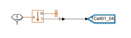
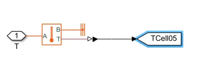
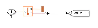
here in the subsystem, we have used a temperature sensor block,
where A point is connected to temperature port and B point is connected to thermal reference.
the T port of temperature sensor block is given to ps- simulink converter and then output of ps- simulink converter is given to goto block
2)
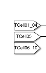
the 3 different from block is then used in the model of respective goto blocks
3)
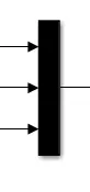
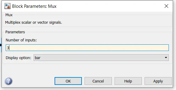
and this 3 from blocks are connected to 3 input mux and the output of mux is connected to scope .
CONVECTIVE HEAT TRANSFER
There is convective heat transfer from battery pack to surrounding
i)
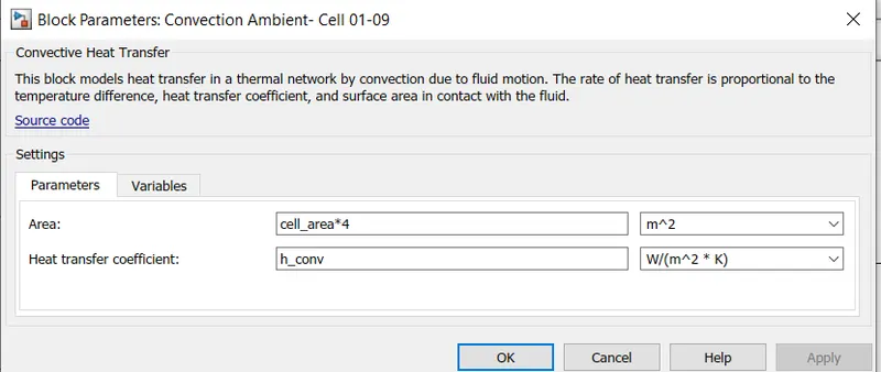
as there as 4 cells (cell 01 to 04) , thus area is cell area*4.
ii)
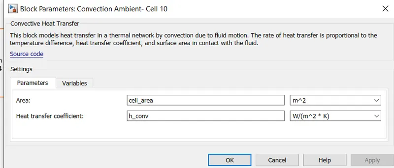
as 5 th cell is faulty and there is only one cell , thus taken cell area only
iii)
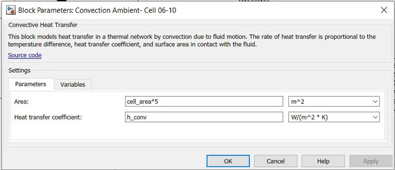
as there as 5 cells (cell 06 to 10) , thus area is cell area*5.
CONDUCTIVE HEAT TRANSFER :
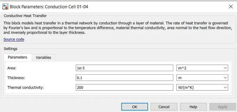
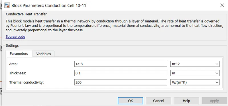
There is conductive heat transfer between the cells of battery pack.
the default parameters are taken in the conductive heat transfer block.
TO MEASURE THE AMBIENT TEMPERATURE:
a temperature sensor block is taken
the A port is connected to ambient temperature
B port is connected to thermal reference
and T port is connected to ps-simulink block
and the output of ps-simulink block is given to scope.
the complete model looks like
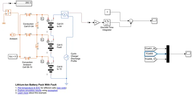
here in this ,model cyclic charge discharge profile considered.
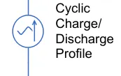
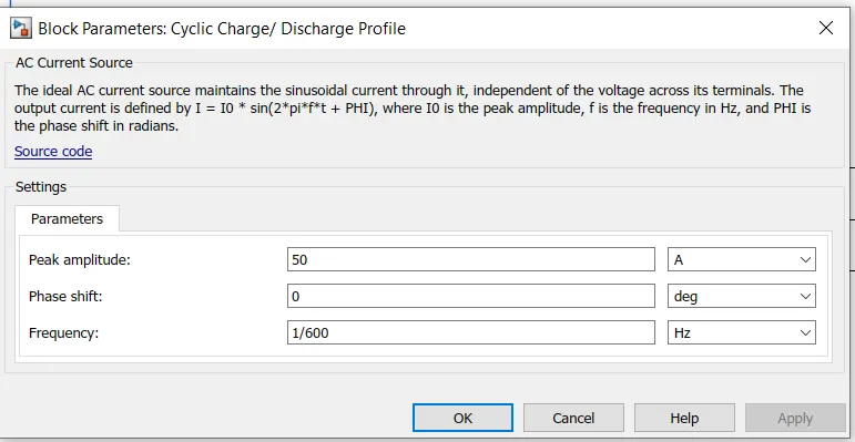
from the parameters , we can see that ,
the peak amplitude of the ac current source is 50 amp
and we have considered phase shift as 0
and frequency is considered as 1/600 hz.
here in this model,
the load is considered in the form of alternating current which is provided by the ac current source block.
AC current source positive terminal is connected to the battery pack and the negative terminal is connected to the electrical reference.
SIMULATION RESULTS:
run simulation for 7200 seconds
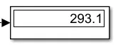
1) the ambient temperature is found to be 293.1K
2) temperature of cells
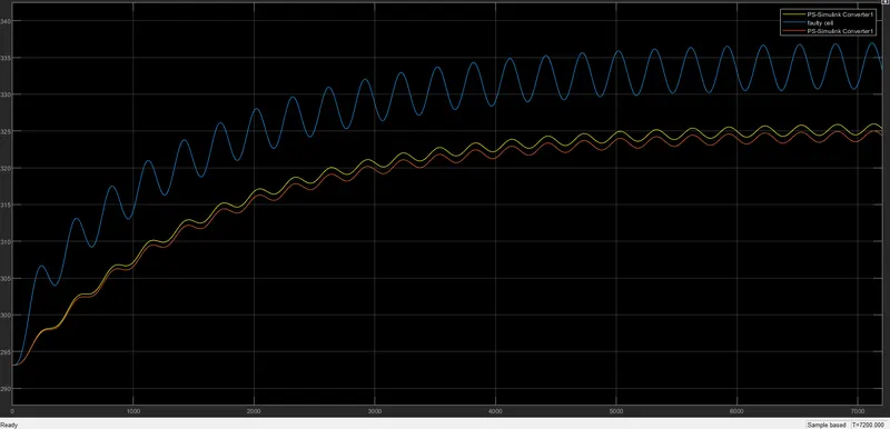
thus from simulation results , we can found that, the faulty cell have higher temperature (blue curve) than the normal cells .
the normal cell temperature is between 295k to 325 k
and the faulty cell temperature is having maximum temperature as 337K.
3) state of charge (SOC)
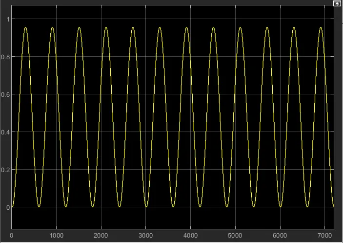
we found that , the SOC graph is fluctuating in the entire 7200 seconds time period.
the soc rises from 0 to 0.95 in 0 to 318 seconds and then fall from 0.95 to 0 in 318 to 600 seconds.
from the plot we found that , there are 6 charging- discharging cycles in 3600 hours
thus we can say that, the life cycle of battery pack is 6 cycles per hour.
this life cycle can be increased if we remove the faulty cell.
CONCLUSION:
thus we found that, if the faulty cell is there in the battery pack , the life cycle of battery pack reduces.
ithe temperature of faulty cell is much higher than normal working cells and because of this high temperature , the efficiency of battery pack gets reduced.
REFERENCES:
https://www.cei.washington.edu/education/science-of-solar/battery-technology/