Week -2
AIM:1) To create a simulink model of doorbell using solenoid block
2)To create a simulink model using a thermistor to sense the temperature of a heater & turn on or turn off the fan.
OBJECTIVES:1) In simulink model of doorbell, we have to create a situation in which the switch will remain close for 2 seconds and then the switch is released and the corresponding iron rod or plunger position is observed.
2) In the thermistor simulink model we have to sense the temperature of a heater & turn on or turn off the fan as per below conditions:
Temperature source: 20 °C from 0 to 10 seconds, 27 °C from 10 to 30 seconds, 23 °C from 30 to 50 seconds
Fan conditions: ON if the temperature above 25 °C, OFF otherwise
OBJECTIVE 1:
THEORY:
ELECTROMAGNET
An electromagnet is a type of magnet in which the magnetic field is produced by an electric current. Electromagnets usually consist of wire wound into a coil. A current through the wire creates a magnetic field which is concentrated in the hole, denoting the center of the coil. The magnetic field disappears when the current is turned off. The wire turns are often wound around a magnetic core made from a ferromagnetic material .
ferromagnetic materials are capable to reach high magnetization levels when subjected to an external magnetic field of relatively low intensity. This property of feromagnetic material is useful in making Ferromagnetic materials are used in a wide range of applications such as sensors, actuators, motors or transformers. Some examples of ferromagnetic substances are iron, cobalt, nickel, gadolinium, and CrO2.
SOLENOIDS
- A solenoid is a long coil of wire wrapped in many turns. When a current passes through it, it creates a nearly uniform magnetic field inside.
- Solenoids can convert electric current to mechanical action, and so are very commonly used as switches.
- The magnetic field within a solenoid depends upon the current and density of turns.
A long straight coil of wire can be used to generate a nearly uniform magnetic field similar to that of a bar magnet. Such coils, called solenoids, have an enormous number of practical applications. The field can be greatly strengthened by the addition of an iron core. Such cores are typical in electromagnets.
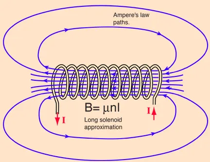
The magnetic field is concentrated intoa nearly uniform field in center of a long solenoid. The field outside is weaker and the lines representing the magnetic field are further apart.
In the above expression for the magnetic field B, n = N/L is the number of turns per unit length, sometimes called the "turns density". The magnetic field B is proportional to the current I in the coil.
within the coils , a strong magnetic field arises whenever current passes through the wire. the direction of magnetic field depends upon the direction of the current.
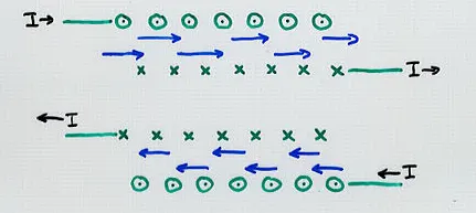
a solenoid acts in the same way like a permanent magnet but the solenoids magnetic field direction can be reversed and we can also turn on or off the magnetic field by controlling the electric current through the solenoid wire.
if we look deep within the solenoid, far from the ends,we can use ampere's law to calculate the field strength.
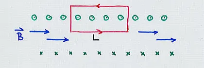
the magnetic field within the solenoid has a uniform value B and outside the coils has value zero.
if there are n coils per meter then

and the integral
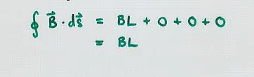
ampere's law allow us to calculate the strength of magnetic field
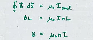
where I= current through wire
n=number of coils per meter.
here in above expression , coil is wounded and air is a medium , as relative permeability of air Ur=1
thus U=Uo*Ur
as Ur=1
thus U=Uo.
PRINCIPLE USED IN DOOR BELL:
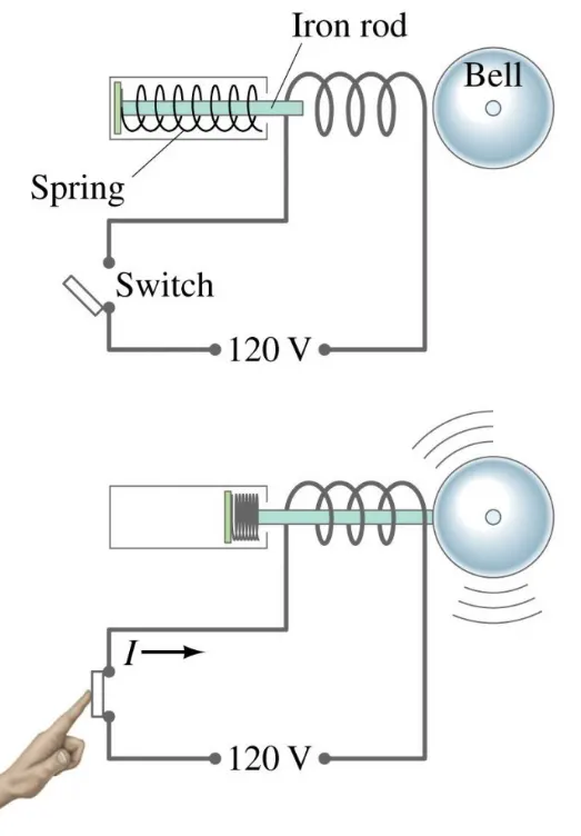
- when the switch is pressed, the current starts flowing in the circuit.
- this current starts flowing though the coil of solenoid
- thus the coil gets electromagnetised and thus magnetic field is produced .
- due to this magnetic field, the iron rod gets attracted towards the coil.
- thus the iron rod gets strike on round shaped iron material.
- when we take our hand away from the switch , the switch gets opened.
- thus current stops flowing in the circuit.
- thus the coil looses its magnetic field
- thus due to spring , the iron rod comes back to its original position.
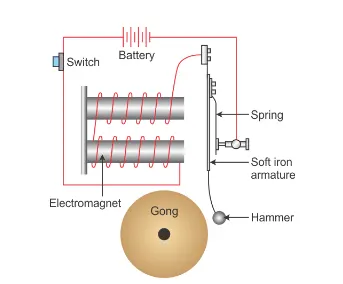
ANOTHER DIAGRAM FOR DOORBELL USING SOLENOID
BLOCKS USED IN SIMULATION MODEL:
1)PULSE GENERATOR: Used to generate pulse signal , which is then given to switch. thus action of switch is controlled by pulse generator.
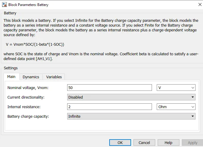
2)BATTERY: used as supply to solenoidal coil
3)SOLENOIDAL BLOCK: solenoidal block is used to produce electromagnetism so that hammer or iron rod will get attracted and bell will ring.
4)ELECTRICAL REFERENCE:to earth all electrical blocks this electrical reference is used
5)MECHNICAL TRANSLATIONAL REFERENCE:used to ground all mechanical blocks.
6)IDEAL TRANSLATIONAL MOTION SENSOR: this block is used to sense any motion
7)SIMULINK-PS CONVERTER : to convert simulink system to physical system
8)DISPLAY BLOCK :to display the result
9)SPST SWITCH: to control the flow of current passing through the solenoid
10)SOLVER CONFUGRATION:used for simulation
11)SCOPE: to display the obtained result in graph format.
SIMULINK MODEL FOR DOORBELL:
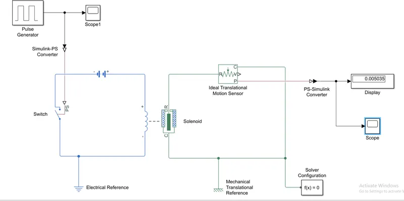
EXPLANATION
- From the above model, a pulse genrator is connected to the switch to control the switching on and switching off of the switch. when the pulse from pulse genrator is present , the switch will remain close, when the pukse from pulse genrator is not present , the switch will remain open.
- Then a solenoidal block and a battery block is taken from library browser. the positive terminal of solenoidal coil is connected to positive terminal of battery and negative terminal of solenoidal coil is connected to negative terminal of battery.
- The switch block is connected in circuit where the battery and solenoidal coil is present.
- Now to operate the switch, the physical signal must be provided to PS port of switch. as pulse genrator siganal is simulink signal and model that we are working on is physical model , thus simulink-PS convertor is used.
- The whole electrical circuit which consist of switch , battery and solenoidal coil is connected to same electrical reference. the electrical reference block must be connected to negative terminal of battery block.
- Now the mechanical circuit have solenoid block and ideal translational motion sensor and this two blocks are connected to mechanical reference.
- The PS-simulink convertor is used to convert physical signals into simulink signals which then is displayed on scope.
BLOCK PARAMETERS OF PULSE GENERATOR
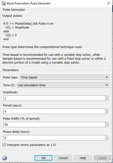
To provide physical signals to switch , the pulse generator is used. we have kept the amplitude of pulse as 1, time period of pulse as 4 seconds and pulse width as 50 percentage of total time period.
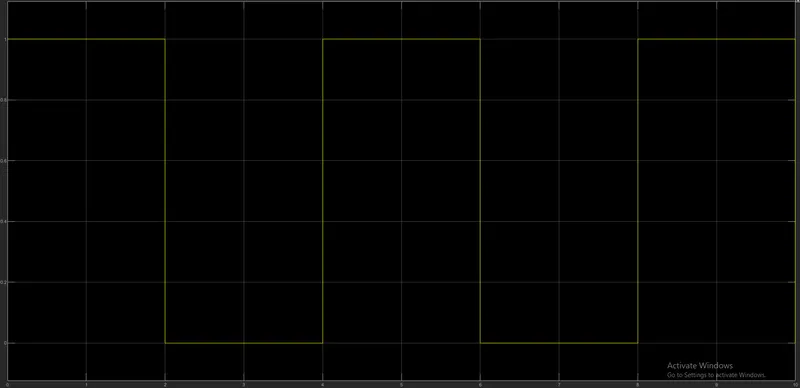
This means that the puLse will be zero initially and then for 0 to 2 seconds , pulse will occur having amplitude as 1 and then between 2 to 4 seconds again the pulse will have zero amplitude and the signals continues. As we have to see the behaviour of iron rod or plunger for switch closed for 2 seconds , thus we have taken pulse having time period as 4 seconds and pulse width as 50 percentage of pulse width.
thus we get following type of input signal.
BLOCK PARAMETERS OF BATTERY
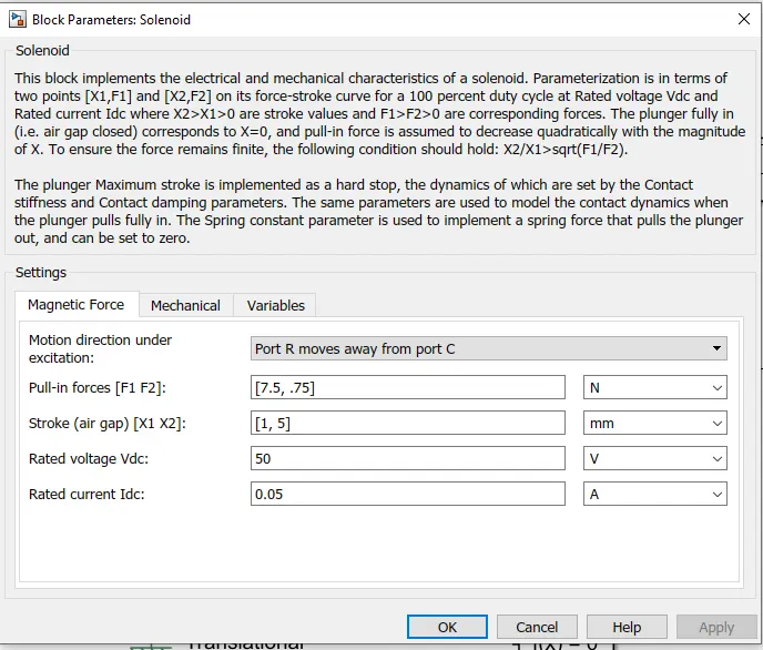
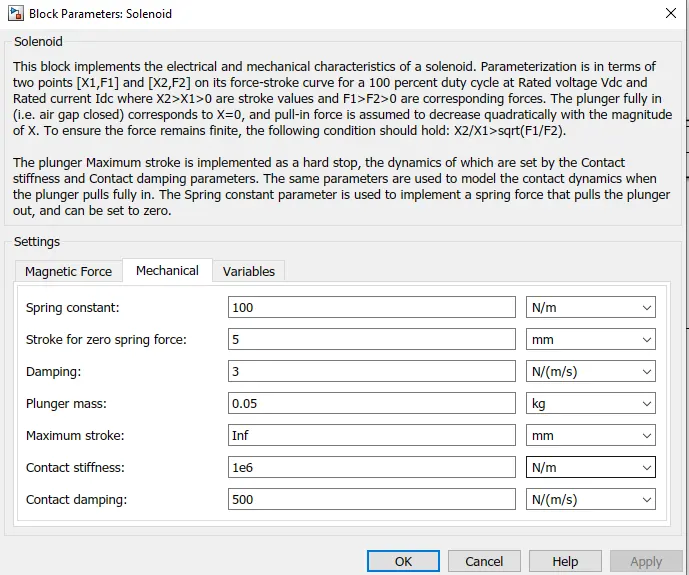
BLOCK PARAMETERS OF SOLENOID
OUTPUT WAVEFORM
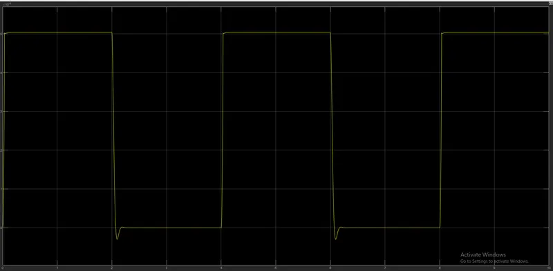
- As the pulse is present between 0 to 2 seconds , thus the switch will get closed and thus circuit will bet closed thus current will start flowing into the electrical circuit.
- Thus the current starts flowing in solenoid coil and thus the coil will energised and thus magnetic field gets created.
- Due to this magetic field, the plunger gets attracted and thus bell rangs .
- Now during 2 to 4 seconds, the pulse from pulse genrator is zero, thus the electrical circuit gets opened ansd thus no current flows in circuit.
- Thus the solenoid coil gets de-energise and thus coil loses electromagnetism thus plunger will get back to its original position due to action of spring.
- Thus between 2 to 4 seconds ,the waveform having zero value because between 2 to 4 seconds the plunger is at intially rest position.
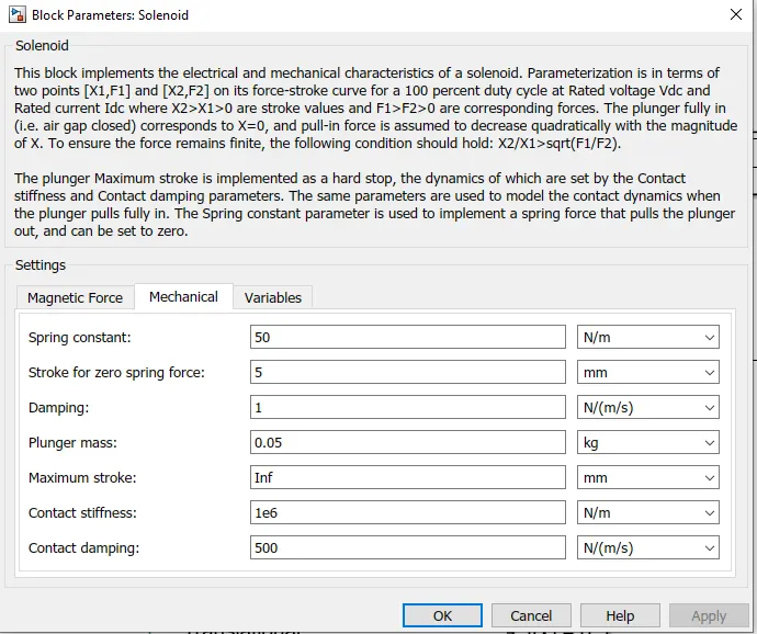
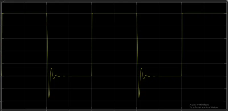
In solenoid block, if spring constant is changed from 100 to 50 and damoing changed from 3 to 1 , we get this waveform in scope block.
Thus to get the smoother graph , we have to change spring constant and damping.
OBJECTIVE 2:
THERMISTOR
A thermistor is a type of resistor whose resistance is strongly dependent on temperature, more so than in standard resistors. The word is a combination of thermal and resistor Thermistors are widely used as inrush current limiters, temperature sensors(negative temperature coefficient or NTC type typically), self resetting over current protectors , and self-regulating heating elements (positive temperature coefficient or PTC type typically).
Thermistors are of two opposite fundamental types:
- With NTC thermistors, resistance decreases as temperature rises usually due to an increase in conduction electrons bumped up by thermal agitation from valency band. An NTC is commonly used as a temperature sensor, or in series with a circuit as an inrush current limiter.
- With PTC thermistors, resistance increases as temperature rises usually due to increased thermal lattice agitations particularly those of impurities and imperfections. PTC thermistors are commonly installed in series with a circuit, and used to protect against overcurrent conditions, as resettable fuses.
Thermistors are generally produced using powdered metal oxides. With vastly improved formulas and techniques over the past 20 years ,NTC thermistors can now achieve accuracies over wide temperature ranges such as ±0.1 °C or ±0.2 °C from 0 °C to 70 °C with excellent long-term stability. NTC thermistor elements come in many styles such as axial-leaded glass-encapsulated (DO-35, DO-34 and DO-41 diodes), glass-coated chips, epoxy-coated with bare or insulated lead wire and surface-mount, as well as rods and discs. The typical operating temperature range of a thermistor is −55 °C to +150 °C, though some glass-body thermistors have a maximal operating temperature of +300 °C.
Thermistors differ from resistance temperature detector (RTDs) in that the material used in a thermistor is generally a ceramic or polymer, while RTDs use pure metals. The temperature response is also different; RTDs are useful over larger temperature ranges, while thermistors typically achieve a greater precision within a limited temperature range, typically −90 °C to 130 °C.
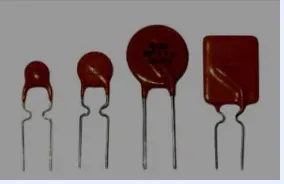
APPLICATIONS OF PTC AND NTC THERMISTORS
- Temperature Compensation
- Temperature Measurement
- Temperature Control
- Inrush Current Limiting
BENEFITS OF PTC AND NTC THERMISTOR
NTC Thermistors are rugged, reliable, and stable, and they are equipped to handle extreme environmental conditions and noise immunity more so than other types of temperature sensors.
- Compact size: Packaging options allow them to operate in small or tight spaces; thereby taking up less real estate on printed circuit boards.
- Fast response time: The small dimensions allow for a quick response to change in temperature, which is important when immediate feedback is required.
- Cost efficient: Not only are thermistors less expensive than other types of temperature sensors; if the purchased thermistor has the correct RT curve, no other calibration is necessary during installation or over its operational life.
- Point match: The ability to obtain a specific resistance at a particular temperature.
- Curve match: Interchangeable thermistors with the accuracy of +0.1˚C to + 0.2˚C.
NEGATIVE TEMPERATURE COEFFIENT THERMISTOR
NTC Thermistors are non-linear, and as their name suggests, their resistance decreases as temperature increases. A phenomenon called self-heating may affect the resistance of an NTC thermistor. When current flows through the NTC thermistor, it absorbs the heat causing its own temperature to rise.
APPLICATIONS
- Temperature Measurement
- Temperature compensation
- Temperature Control
BENEFITS
- Fast Response Time to (±1%).
- Accuracy: NTC thermistors have an accuracy range of 0.05 to 0.20 ˚C with long-term stability. Other temperature sensors can drift over time.
- Packaging: NTC thermistors are customizable to meet different application requirements.
- Noise Immunity: NTC thermistors offer excellent immunity to electrical noise and lead resistance more so than other types of temperature sensors.
- Cost efficient: Because of their small size and ease of production, NTC and PTC thermistors prove to be very economical choices.
POSITIVE TEMPERATURE COEFFIENT THERMISTOR
Positive Temperature Coefficient thermistors (PTC) offer a passive approach to limiting inrush current. By implementing a PTC thermistor, you’ll likely see a reduction in operating costs with higher reliability; without compromising protection. PTC thermistors experience a change in resistance if there is a change in the ambient temperature or the device self-heats because it absorbs incoming current. And, since limiting inrush current relies on the specified resistance of a PTC thermistor, making the right selection plays a crucial role in system protection.
PTC THERMISTOR TYPES
- Ceramic Switching PTC Thermistors
- Silistor Silicon PTC Thermistors
- Polymer PPTC Thermistors
GENERAL PTC THERMISTOR APPLICATION
- Time Delay
- Degaussing
- Motor Starting
- Overcurrent Protection
DESCRIPTION OF MODEL
- To create this model , basic blocks like thermistor block, battery , voltmeter, resistor are required.
- from the library browser, thermistor block is taken.
- battery is connected to thermistor in such a way that positive of battery is connected to positive terminal of thermistor.
battery parameters are shown below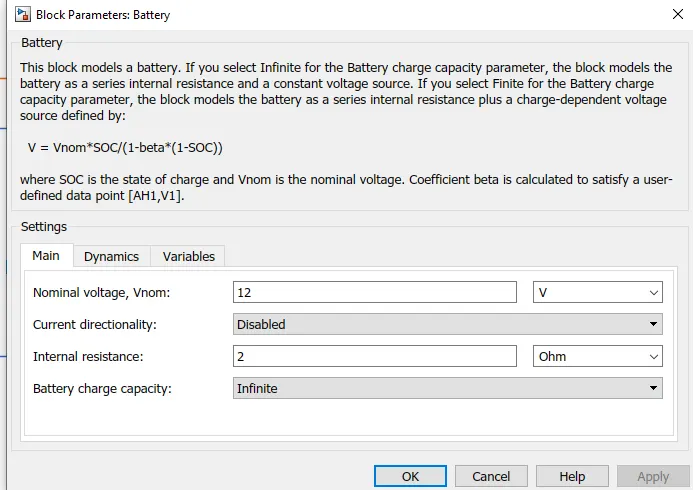
let the voltage of battery be 12volts. - a resistor is connected between thermistor block and resistor block.
- to measure the voltage across the resistor, a voltmeter called as voltage sensor is connected in parallel to resistor.( voltmeter is always connected in parallel)
- all this electrical block like thermistor, battery and resistor is connected to each other and this electrical circuit is connected to electrical reference
- this electrical refernence is considered as earthing in real time application.
- as per our objective, fan must get on and off at different temperatures.
- to provide this range of temperatures , we need a controlled temperature source block which will give specified temperature as output even when there will be heat flow.
- for providing input to this controlled temperature source block, we use signal builder block.
- in this signal builder block , we can design our own desired signal.
- in signal builder block, by changing the x and y axis as per our requirement, we can prepare our own signal.
- the signal built in signal builder is shown below
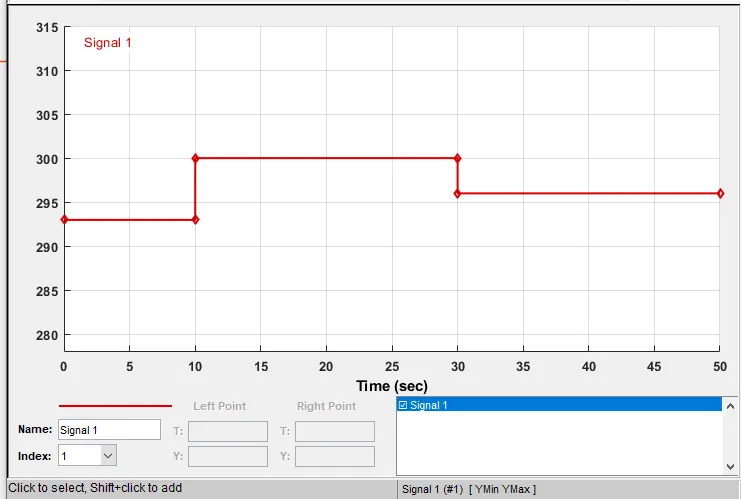
14.as given in que that ,Temperature source: 20 °C from 0 to 10 seconds, 27 °C from 10 to 30 seconds, 23 °C from 30 to 50 seconds , thus this signal is developed accordingly.
15.to convert this signal into physical value , simulink-PS converter block is used.
16.the port B of controlled temperature source block is connected to port A of thermistor block and the port A of controlled temperature source block is connected to the thermal reference.
17.the output of voltage sensor block is connected to PS-simulink converter.
18. as per question, the fan must be on when temperature is more than 25degree celsius i.e. 298 deg kelvin ie fan must get on between 30 to 50 seconds and at all other seconds except this time range ,the fan must get off.
19.to control the fan movement , a switch block is used. the port of switch block is connected tp constant value 1 and lower port of switch block is connected to constant value 0.
20.the center [port odf switch block is a condition input .
21. the scope of voltage sensor block is shown below
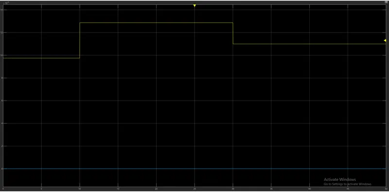
the value of voltage between the time range of 30 to 50 sec is 10.98 milli volt.
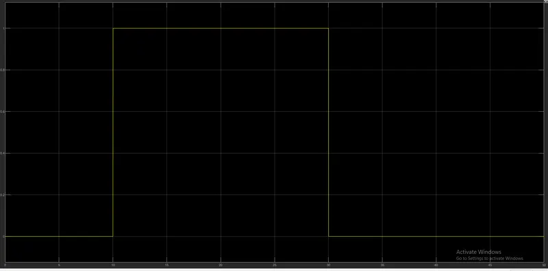
as per question , the fan must get on when temperture rises above 25 deg celsius, thus as per signal builder scope , the fan must get on between 10 to 30 seconds.
22. thus the threshold value of switch block is given as 10.98 milli volt.
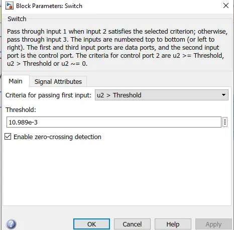
23.thus when voltage gets more than 10.98 milli volt , the output of switch block will be 1 which means fan is on. if voltage is below 210.98 milli volt, the output of switch block will be 0,which means fan is off.
24.output of switch block is shown below
CONCLUSION:1)Thus both objectives were achieved successfully
2) similar logic can be applied to various other physical systems.
REFERENCES