Project
AIM: to study and to analyse the BAJA all terrain vehicle ATV model .
OBJECTIVES: to study the various results obtained from the model and to prepare a detail report based on results obtained.
the models that we have to study are
1)BAJA ATV MODEL WITHOUT A DASHBOARD:
2)BAJA ATV MODEL WITH DASHBOARD
3)BAJA ATV model using lookup table without dashboard.
4)BAJA ATV model using lookup table with dashboard.
THEORY:
DEFINATION OF ALL TERRAIN VEHICLE
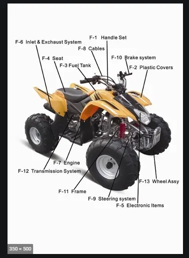
The term ATV stands for All Terrain Vehicle. It is also known as a quad or quadricycle type vehicle. An All-Terrain motor vehicle could have three, four or even six wheels. Unlike a motorcycle, generally, the ATVs have more than two wheels. This vehicle runs on low-pressure tires. However, it has handlebars instead of wheel for controlling the steering.
As the name indicates, an ATV is designed to handle a broader variety of terrain than regular vehicles. In some countries it is a street-legal motor vehicle and licensed for use on public roads. However, it is not street-legal or roadworthy within some states, territories, and provinces of some countries.
Riding An ATV:
The riders ride an All Terrain Vehicle by siting on it just like a motorcycle. However, you don’t need much effort to balance it because extra wheels give more stability at slower speeds. Also, most dirt bikes are considered the ATVs because they are designed for off-road use only. Generally most ATVs come with three or four wheels. However, some specialized applications require six-wheel models. Engine sizes of ATVs range from as low as 49ccto 1,000cc. However, the size of the engine depends upon the application.
Generally, the intended use of All Terrain Vehicles is by a single operator only. However, some manufacturers make ATVs for use by two. Of them, one is the operator and other is passenger. So, manufacturers refer these ATVs as Tandem ATVs. The rider or main operator must wear a helmet just like a motorcycle rider. However, in some countries, it is not mandatory for the passenger to wear a helmet.
Develpoment:
The development of the All Terrain Vehicles started way back in the early 19th century. In 1893, Royal Enfield manufactured and sold the first powered quadricycle. The vehicle employed many bicycle components such as the handle bars. However, it was mainly designed for use as a horseless carriage for road use.
Most earlier generation ATVs had large balloon tires instead of a mechanical suspension. However, by the early 1980s, manufacturers introduced All Terrain Vehicles with better components like suspension, racks and lower-profile tires. In the late 1980s, due to safety issues with three-wheel ATVs, manufacturers upgraded them to four-wheel models. Later, manufacturers like polaris designed & developed the ATVs with six wheels for specialised operations such as military.
USES OF ALL TERRAIN VEHICLE:
- Killing Weeds. ...
- Camping. ...
- Winching. ...
- Hunting. ...
- Field Plowing. ...
- Lawn/Field Mowing. ...
- Seed/Salt/Rock Spreading.
- Snow Plowing.
INFORMATION OF BAJA SAE:
Baja SAE is an design series competition run by the SAE International. Teams of students from universites all over the world design and build small off-road cars. The cars all have engines of the same specifications.
The goal in Baja SAE racing is to design, build and race off-road vehicles that can withstand the harshest elements of rough terrain. The vehicles used in Baja SAE racing are often similar in appearance to dune buggies. Before 2007, the events were called "Mini Baja."
Each year as many as 141 Baja cars are entered in the Baja SAE events across the US and around the world. International events are endorsed by SAE International and are held in Brazil, Korea, South Africa and México.
All cars must adhere to SAE International's rules, and pass SAE's technical inspection and judging; a car may not race until all safety inspections are passed. Small engine manufacturer briggs and stratton sponsors Baja SAE teams by providing the SAE sanctioned engine free of charge, at a replacement rate of one engine for every two years in competition.
There are multiple dynamic events, . The dynamic events include hill climbs, sled pulls, maneuverability events, rock crawl, and suspension & traction events. Previously the cars had to be able to float and propel itself on water under its own power. This was changed from the 2012 competitions onward due to safety concerns.
Static events, such as written reports, presentations and design evaluations are provided by participating teams. This is when the teams are judged on ergonomics, functionality, and producibility of their cars; ensuring that the final placement of the team does not rest solely on the vehicle's performance but rather on a combination of static and dynamic events. Required reports detail the engineering and design process that was used in developing each system of the team's vehicle, supported with sound engineering principles.
Also, a cost report that provides all the background information necessary to verify the vehicle's actual cost is used to rate the most economically feasible for production. These reports are submitted weeks in advance of each event, where the presentations and design evaluations are given on site in the presence of SAE design judges. Teams with noticeable differences between the car and the cost report can be audited, where if the report and car do not match, the team will be served penalty points.
1)CONTINOUSLY VARIABLE TRANSMISSION:
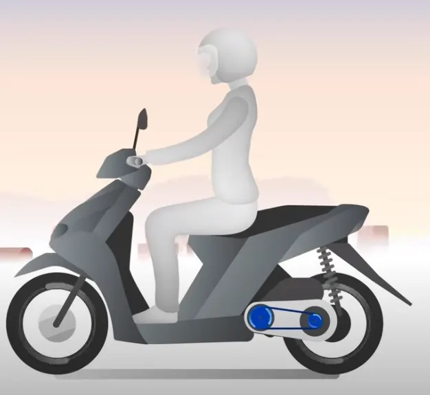
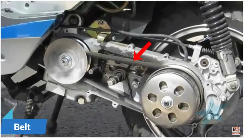
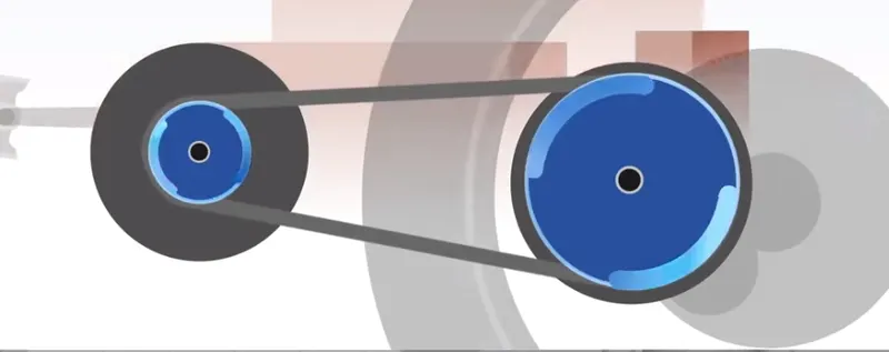
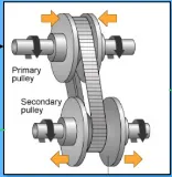
to understand continously variable tranmisson properly , let consider CVT installed in scooter.
Continously variable tranmisson is placed here as shown in figure.
in CVT we have two pulleys namely
1) driver pulley
2) driven pulley
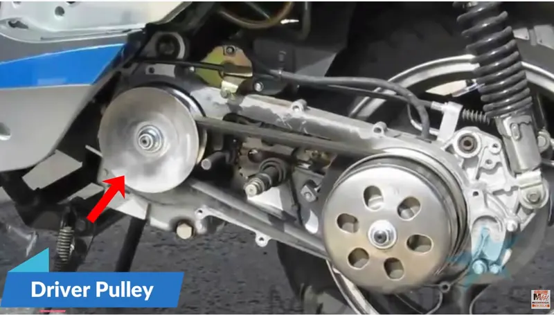
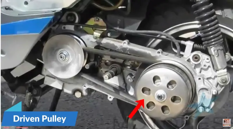
this both pulleys are connected to each other through belt.
driver pulley with the help of the belt drives the driven pulley.
driver pulley have two conical plates namely,
1) fixed plate-which is connected to engine input shaft and it do not move
2)conical plate-it is movable, it slides on surface of the shaft.
same construction is applicable to driven pulley.
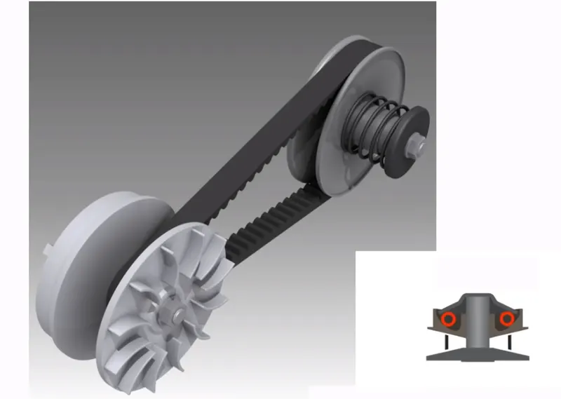
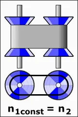
when movable plate comes near the fixed plate, the driver pulley will have a larger diameter and this time , the belts are also increases to maximum and belt will start rotating at the outer surface of driver pulley. at this case,the rare pulley ie driven pulley will rotate fast and thus the speed increases.
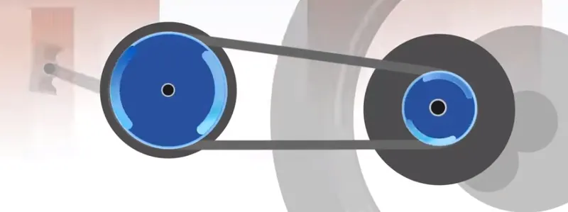
when movable plate moves away from the fixed plate, the driver pulley will have a small diameter and this time , the belt IS also decreases to minimum and belt will start rotating at the inner surface of driver pulley. at this case,the rare pulley ie driven pulley will rotate slow and thus the speed decreases.
ADVANTAGE OF USES AN CONTINOUSLY VARIABLE TRANSMSSION:
1)One of the advantages of a CVT is its ability to continuously change its gear ratio. This means that no matter what the engine speed it, it is always performing at its peak efficiency. CVTs often offer better fuel economy as a result, especially when driving in the city.
2)most cars equipped with CVTs offer a smoother ride .This is because the transmission never shifts.
3)A CVT is lighter than a traditional automatic, and this, combined with the smoother operation, helps to improve the fuel efficiency of vehicles that come equipped with a CVT.
4)Because of the lack of gearing, it is easier for CVT vehicles to find and maintain an ideal torque ratio as well. It has an easier time taking off from a stoplight and an easier time climbing difficult terrain because the variable transmission allows it to run in the right "gear" and stay there.
5)They have a more connected feeling between the engine and the speed of the vehicle.
6)The driver has a better sense of control with actual upshifting and downshifting.
7)Automatic transmissions are less expensive to maintain.
8)They offer a more engaging driving experience.
DISADVANTAGE OF USES AN CONTINOUSLY VARIABLE TRANSMSSION:
1)While the lack of upshifting and downshifting is considered an advantage of the CVT, some drivers miss the sensation of the vehicle moving through the shift points. If you prefer a sportier driving experience, then the lack of fixed gears makes the ride less engaging.
2)Another complaint that drivers tend to make about a CVT is the loud droning sound that occurs during acceleration. This happens because the CVT forces the engine to continuously run a constantly high rpm as it gets up to speed.
3)CVTs can be expensive to repair or replace
4)Some of the common problems that owners run into include overheating, slipping, and sudden loss of acceleration. Shuddering is also a common problem.
5)Since CVTs depend on the belts to operate, if these suffer from excessive stretching or too much wear, the transmission can completely fail.
6)CVTs are harder to work on. Even basic maintenance often needs to be done by a trained mechanic.
7)They don't last as long as a conventional transmission.
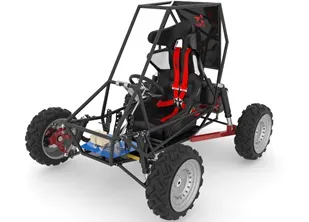
2)VEHICLE BODY:A vehicle body frame structure for an all-terrain vehicle having at least a front wheel, and including a first frame assembly and a second frame assembly. The first frame assembly includes an arm support portion and a steering shaft support portion located at a front portion of the vehicle body frame structure, for steering the front wheel. The second frame assembly is bisected from the first frame assembly; and the vehicle body frame structure also includes a suspension arm vertically swingably supported by the arm support portion.
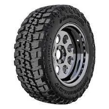
3)TIRE: The vehicle body is connected to 4 tires each per axle so that the vehicle move according to power input to axle.
4)SUSPENSION:There are different types of suspension system which can be used for a vehicle depending
upon our need. Basically suspension can be classified into 2 types:
1 Independent suspension
2 Dependent suspension
1) Independent Suspension : The term independent indicates that suspension system for both
the wheels are independent of one another i.e., whenever a bump or droop comes across ,both
the wheels behave independently. To put it up in simple terms the wheel travel ( movement of
wheel up and down in vertical direction) can be seen only on that side where the wheel
undergoes bump or droop. Where as the other wheel maintains contact with the road
2)Dependent Suspension : In this type suspension if one wheel undergoes a wheel travel
due to bump or droop the opposite wheel also undergoes the wheel travel, Unlike the
independent suspension.
For an all terrain vehicle where the vehicle is made to run at different uneven terrains it is
always better to opt for independent suspension system rather than dependent suspension. Of
all the independent suspension systems available by studying the merits and demerits of each
and every type, double wishbone and trailing arm suspension have been preferred for front
and rear respectively.
The main functions of the suspension system in vehicle are:
i) To maintain traction between the tires and ground
ii) To improve vehicle handling
iii) To provide a ride comfort to the passengers
BLOCKS USED IN SIMULINK MODEL:
1) SIGNAL BUILDER: To input the brake and throttle input.
2)SIMULINK TO ps cinverter: to convrert the simulink signal to simscape environment.
3 generic engine: speed and torque values are given to the generic engine block.
4)inertia: to represent inertia
5)rotational motion sensor:a device that converts an across variable measured between two mechanical rotational nodes into a control signal proportional to angular velocity or angle.. here this block is used to sense the rotational motion from engine and give output as rpm
6)PS terminator: to cap physical signal output ports that do not connect to other blocks. this is used as terminator for uncoonected physical
signal output.
7)mechnanical reference: to ground all the mechanical components to the ground.
8)tire:for transportation of vehicle.
9)vehicle body : to represnt body of a vehicle.
10)PS constant block:The PS Constant block generates a physical signal of a constant value
11)double shoe brake: represents a frictional brake with two pivoted rigid shoes that press against a rotating drum to produce a braking action.
12)inertia:The Inertia block represents an ideal mechanical translational inertia
13)simple gear:to adjust the speed of the engine .
14)variable ratio transmission: a gearbox that dynamically transfers motion and torque between the two connected driveshaft axes, base and follower.
15)solver confugration: to specify solver parameter before starting of simulation.
16)scope; to view the outpurt in graph format
17)variable gear ratio: to vary the speed according to gear ratio
1)BAJA ATV MODEL WITHOUT A DASHBOARD:
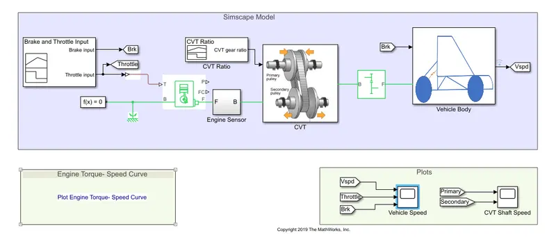
PARAMETERS OF EACH BLOCKS USED IN MODEL:
1)SIGNAL BUILDER:
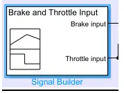
the throttle input and the brake input is generated by using signal builder block.
2)GENERIC ENGINE
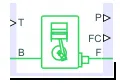
The Generic Engine block represents a general internal combustion engine. Engine types include spark-ignition and diesel. Speed-power and speed-torque parameterizations are provided. A throttle physical signal input specifies the normalized engine torque. Optional dynamic parameters include crankshaft inertia and response time lag. A physical signal port outputs engine fuel consumption rate based on choice of fuel consumption model.
T-This is input port respresenting normalized engine throttle level , this is unitless
P-this is a output port which represents instantaneous engine power, unit is watts.
FC- this is output port , which represents fuel consumption rate ,unit is kg/s
B- engine block
F-engine crankshaft
3) SIMPLE GEAR:
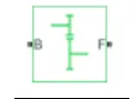
B- base
F-follower
The Simple Gear block represents a gearbox that constrains the connected driveline axes of the base gear, B, and the follower gear, F, to corotate with a fixed ratio that we specify.
to connect CVT and engine , we need some speed reduction , thus we use simple gear block.
4) CVT:
Let we have prepared a subsystem CVT as shown.
if we click on this , we get the model for CVT as
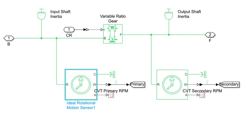
let first consider
a) variable gear ratio block
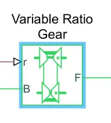
The Variable Ratio Transmission block represents a gearbox that dynamically transfers motion and torque between the two connected driveshaft axes, base and follower
B and F are rotational conserving ports representing, respectively, the base and follower driveshafts.
to specify the gear ratio , we have a variable gear ratio block.
b) ideal rotatonal motion sensor
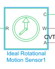
The Ideal Rotational Motion Sensor block represents an ideal mechanical rotational motion sensor, means a device that converts an across variable measured between two mechanical rotational nodes into a control signal proportional to angular velocity or angle
Connections R and C are mechanical rotational conserving ports that connect the block to the nodes whose motion is being monitored. Connections W and A are physical signal output ports for velocity and angular displacement, respectively.
The block positive direction is from port R to port C. This means that the velocity is measured as ω = ωR – ωC, where ωR, ωC are the absolute angular velocities at ports R and C, respectively.
this are nothing but a sensor , which give rpm of primary and secondary.
c) inertia block
The Inertia block represents an ideal mechanical translational inertia, described with the following equation:
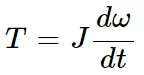
where:
T = inertia torque.
J = inertia.
ω = angular velocity.
t = time.
the block has one mechanical translational conserving port. The positive direction of block is from its port to the reference point. This means if inertia is accelerated in positive direction than the inertia torque is positive.
the input shaft inertia and output shaft inertia represents primary and secondary pulley
5) engine sensor
if the subsystem engine sensor is right clicked , we get the following model,
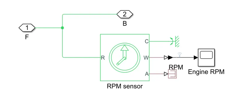
a) rpm sensor
this is ideal rotational motion sensor only.
b)PS terminator
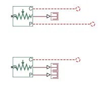
the PS Terminator block is used to cap physical signal output ports that do not connect to other blocks.
Unlike conserving ports in physical modeling, or Simulink® output ports, unconnected physical signal output ports do not generate warnings. However, you can use a PS Terminator block for clarity, to indicate that the signal was not inadvertently left unconnected.
The block icon size allows you to connect the PS Terminator block to an open port without rerouting the adjacent lines like
5) VEHICLE BODY:
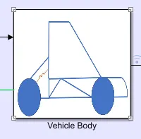
The vehicle body model looks like,
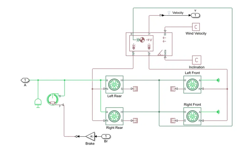
a)Vehicle body
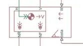
The Vehicle Body block represents a two-axle vehicle body in longitudinal motion. The vehicle have the same or a different number of wheels on each axle. For example, two wheels on the front axle and one wheel on the rear axle. The vehicle wheels are assumed same in size. The vehicle can also have a center of gravity (CG) that is at or below the plane of travel.The block accounts for body mass, aerodynamic drag, road incline, and weight distribution between axles due to acceleration and road profile. Optionally include pitch and suspension dynamics. The vehicle does not move vertically relative to the ground .The block has an option to include an externally-defined mass and an externally-defined inertia.
W- it is an input port , represents headwind spped in m/s
beta- it is road inclined angle measured in radian
CG- it is also input port represents center of gravity in meters.
M- mass in kg
j- is is also a input port represents External moment of inertia
V- it is output port represents longitudinal velocity
NF- it is an output port represents front axle normal force
NR- it is also a output port represnts rear axle normal force
H- horizontal motion
b)DOUBLE SHOE BRAKE
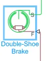
The Double-Shoe Brake block represents a frictional brake with two pivoted rigid shoes that press against a rotating drum to produce a braking action. The rigid shoes is placed inside or outside the rotating drum in a diametrically opposed configuration. A positive actuating force causes the rigid shoes to press against the rotating drum. Double-shoe brakes provide high braking torque with small actuator deflections in applications that include motor vehicles and some heavy machinery.
F- actutating force
S- Drum shaft rotation.
c) TIRE
the body of a vehicle is placed over 4 tires so that the vehicle can move .
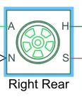
N- normal force
S- slip
A- axle
H- mechanical translational port.
PROCESS:
1) the throttle input is produced by signal builder block, and this input is then connected to engine and the brake input signal is also genrated by signal builder block.
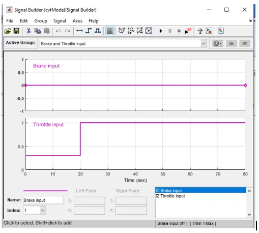
2) the engine will generate the output which is rpm . this output is given to ideal rotational motion sensor which will sense the rpm.
3)then this output is given to the CVT and again the CVT ratio is generated by signal builder block as shown.
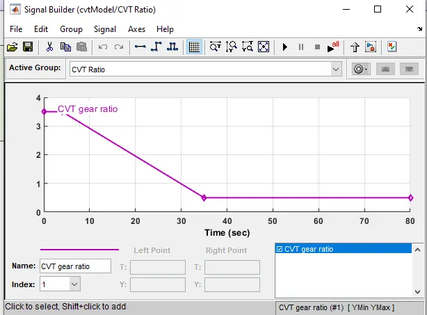
4) the output of the CVT is given to simple gear . to connect CVT and engine , we need some speed reduction , thus we use simple gear block.
5) the velocity is taken as output from vehicle block.
RESULTS ANALYSIS:
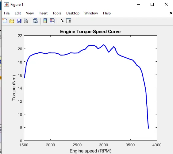
1) ENGINE SPEED AND TORQUE GRAPH:
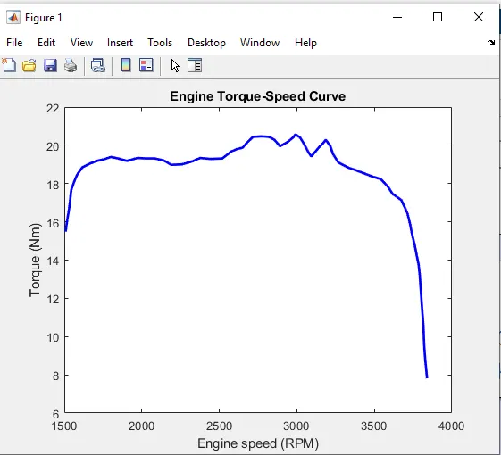
the graph shows the variation in torque and corresponding variation in engine speed.
2) VEHICLE SPEED PLOT
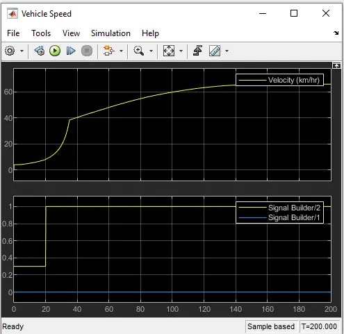
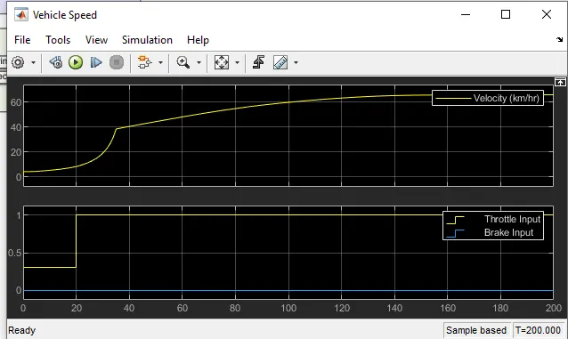
in this model , the brake input is not given and throttle input is given 0.3 upto 20 seconds and then 1 after 20 seconds and we observed that the velocity increases as the throttle input increases.
as we can see that , the value of velocity is near about 64 km/hr at full throttle=1 at near about 140 second and then the velocity remains almost constant.
3)CVT SPEED PLOT
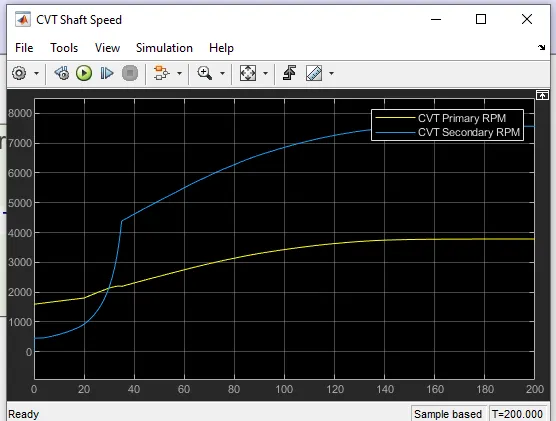
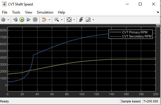
here two graphs are plotted , one for CVT primary RPM and other for CVT secondary RPM.
2)BAJA ATV MODEL WITH DASHBOARD
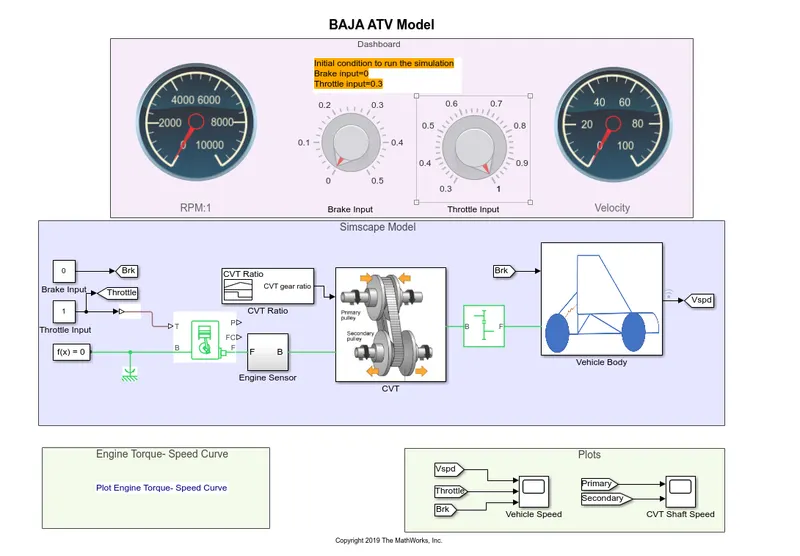
this model works same as baja ATV model without dashboard ,the only difference is that , the throttle and the brake inputs are controlled by the user using the knob.
RESULTS OBTAINED:
1) VEHICLE SPEED GRAPH:
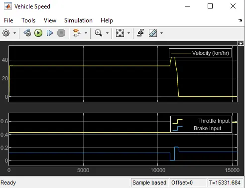
Thus as brake and throttle input changes , the velocity also changes.
2)CVT SPEED GRAPH:
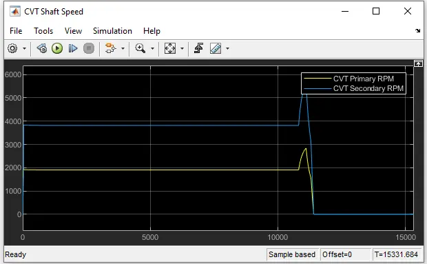
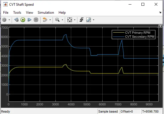
the CVT primary RPM and CVT secondary rpm results are shown in the above graph.
3)BAJA ATV model using lookup table without dashboard.
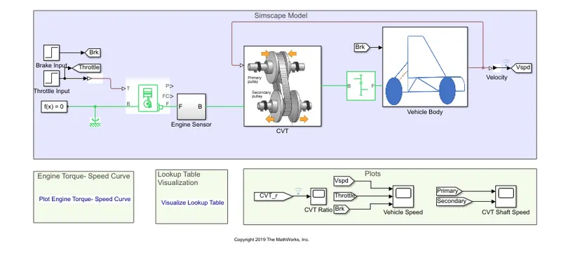
if we click the CVT block , we get model like
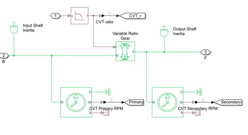
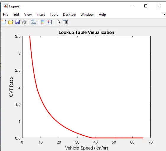
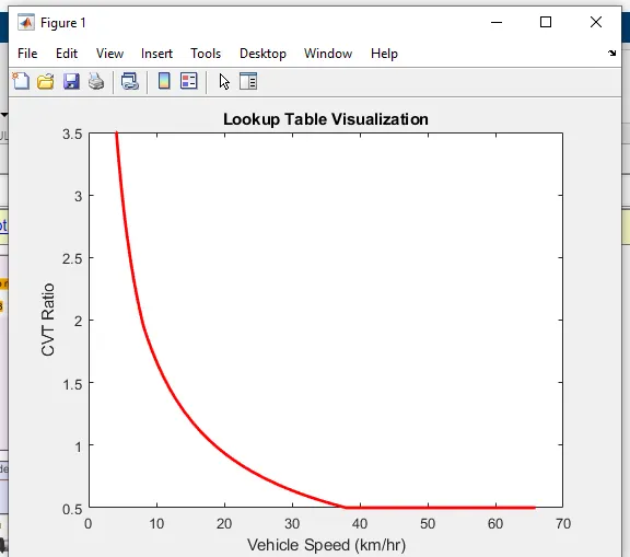
here the gear ratio inputs to CVT is given using lookup table. all the other parameters are same as before only.
LOOK UP TABLE VISUALIZATION
OUTPUTS
A) VEHICLE SPEED VARIATION BY VARYING THROTTLE AND SPEED
B) CVT SHAFT SPEEDS
4)BAJA ATV model using lookup table with dashboard.
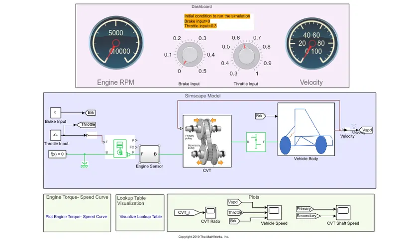
in this model , the knobs are used to control the inputs that is throttle and brake.
other all things is same as explained previously.
LOOK UP TABLE VISUALIZATION
OUTPUT:
A) VEHICLE SPEED VARIATIONS BR VARYING THROTTLE AND BRAKE INPUTS
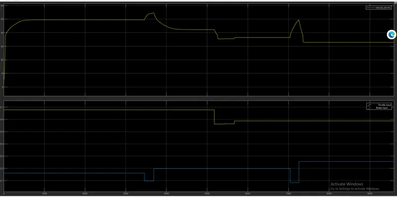
This graph is near about same that we have obtained in BAJA ATV MODEL WITH DASHBOARD, Here the velocity gets varied as throttle input and brake input varies. as brake input increases , the speed of vehicle decreases.
and as throttle input increases , the vehicle velocity also increases.
B) SHAFT RPM
CONCLUSION:
Thus we have studies all four models and the results are analysed properly .
REFERENCES:
https://www.atvcourse.com/blog/2011/06/13-surprising-uses-for-atvs/
https://www.caranddriver.com/research/a31517125/cvt-transmission-vs-automatic-quick-guide/