Project 2 Thermal modeling of battery pack
Aim-For a 10-cell series lithium-ion battery model, simulate the thermal effects and compare life cycle performance at various temperatures, charge & discharge rates using MATLAB.
==================================THEORY====================================
Lithium-ion (Li-ion) batteries are widely used for various applications such as telecommunication, automotive, and stationary applications. With their wide range of safe operating temperatures (i.e. -10 °C to 50 °C), Li-ion is preferred over other types of matured battery technologies such as lead acid and nickel-cadmium (NiCd). Nevertheless, operating the Li-ion batteries in cold climate conditions can potentially harm the batteries and lead to degradation and reduced capacity and power density.
Lithium-ion batteries, with high energy density (up to 705 Wh/L) and power density (up to 10,000 W/L), exhibit high capacity and great working performance. As rechargeable batteries, lithium-ion batteries serve as power sources in various application systems. Temperature, as a critical factor, significantly impacts the performance of lithium-ion batteries and limits the application of lithium-ion batteries. Moreover, different temperature conditions result in different adverse effects. Accurate measurement of temperature inside lithium-ion batteries and understanding the temperature effects are important for proper battery management. We discuss the effects of temperature on lithium-ion batteries at both low and high-temperature ranges. The current approaches to monitoring the internal temperature of lithium-ion batteries via both contact and contactless processes are also discussed.
Lithium-ion batteries (LIBs), with high energy density and power density, exhibit good performance in many different areas. The performance of LIBs, however, is still limited by the impact of temperature. The acceptable temperature region for LIBs normally is −20 °C ~ 60 °C. Both low temperature and high temperature that are outside of this region will lead to degradation of performance and irreversible damages, such as lithium plating and thermal runaway. Therefore, understanding the temperature effects and accurate measurement of temperature inside lithium-ion batteries are important for the proper battery management. The state-of-art achievements in monitoring the temperature inside the LIBs can be divided into contact measurement and contactless measurement. This review overviews recent development in both the understanding of the temperature effects and the temperature monitoring, and discusses the challenges and possible future directions in achieving optimum battery performance.
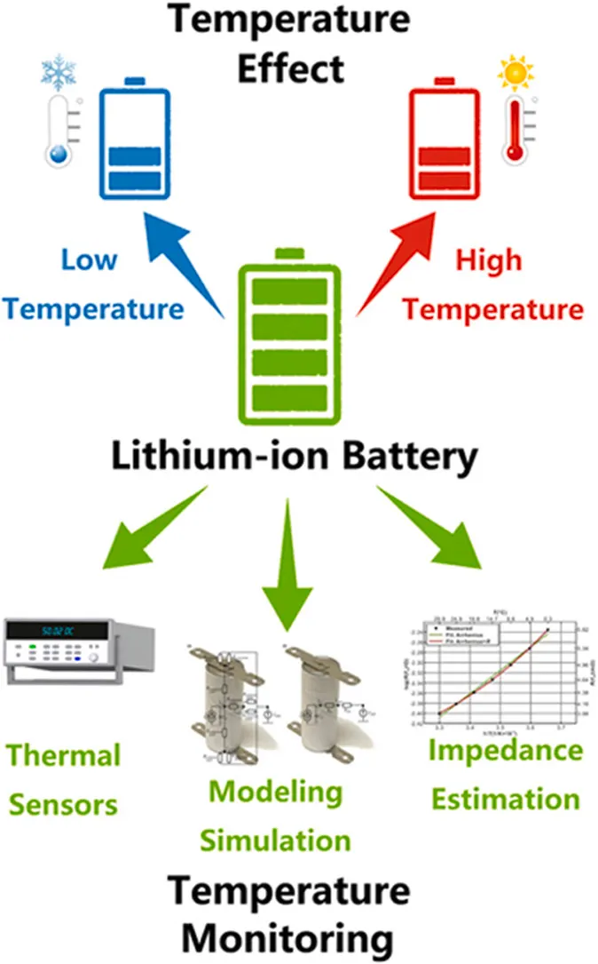
The effects of temperature to LIBs
Most of the temperature effects are related to chemical reactions occurring in the batteries and also materials used in the batteries. Regarding chemical reactions, the relationship between the rate of chemical reactions and reaction temperature follows Arrhenius equation, and temperature variation can lead to the change of electrochemical reaction rate in batteries. Besides chemical reactions, the ionic conductivities of electrodes and electrolytes are also affected by temperature. For example, the ionic conductivity of lithium salt based electrolytes decreases at low temperatures. With these effects in concern, the LIBs used in EVs and HEVs can hardly meet the expectation of a 10-year life suggested by the United States Advanced Battery Consortium (USABC). In the following sections we will discuss both the low temperature effects and the high temperature effects on the LIBs.
Low temperature effects
The performance of LIBs will degrade at temperatures below 0 °C. In 2001, Nagasubramanian showed that the power and energy densities of Panasonic 18650 LIBs were ~800 W/L and ~100 Wh/L at 25 °C, and these values were reduced by 98.75% and 95% to < 10 W/L and ~5 Wh/L at −40 °C. In another report, the state of charge (SOC) of a LIB, which is defined as the ratio of the present residual capacity to the overall available capacity, was also found to decrease by ~23% when the operating temperature decreased from 25 °C to −15 °C.
With the complex material system used in LIBs, the performance degradation at low temperatures can be attributed to several different sources. First, the low temperature will affect the property of electrolytes. With the decrease in temperature, the viscosity of the electrolyte will increase, which will reduce the ionic conductivity. The internal resistance will subsequently rise due to the increase in the impedance of the directional migration of chemical ions. To counter such effect, electrolytes with low freezing points were explored, and different electrolyte additives were studied
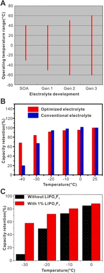
Fig. 2. Researches on electrolytes for improving the performance of LIBs at low temperatures. (A) Comparison of the operating temperature range between three generations of electrolytes (Gen 1, Gen 2 and Gen 3) of Exploration Systems Missions Directorate (ESMD) programs and the state of art (SOA) operating temperature range. Reproduced with permission from Copyright: 2007, IEEE. (B) Comparison of the capacity retention at different temperatures between the optimized electrolyte and conventional electrolyte. Reproduced with permission from. Copyright: 2017, American Chemical Society. (C) The effect of using LiPO2F2 as the additive to the electrolyte on the capacity retention at different temperatures. Reproduced with permission from. Copyright: 2008, Elsevier.
The increase of charge-transfer resistance in LIBs is also an important factor that contributes to performance degradation at low temperatures. The charge-transfer resistance of LiFePO4-based cathodes at −20 °C was reported to be three times higher than that at room temperature [76]. Such high charge-transfer resistance largely affects the kinetics in batteries. The study of LIB performance at low temperatures by Zhang et al. demonstrated that the charge-transfer resistance significantly increased when the temperature decreased. The charge-transfer resistance of a discharged battery normally is much higher than that of a charged one. Charging a battery at low temperatures is thus more difficult than discharging it. Additionally, performance degradation at low temperatures is also associated with the slow diffusion of lithium ions within electrodes. Such slow down can be countered by altering the electrode materials with low activation energy. For example, Li3V2(PO4)3 (LVP), which has an activation energy of 6.57 kJ mol–1, showed a 200x improvement of apparent chemical diffusion coefficient of lithium ions over LiFePO4 (LFP) with an activation energy of 47.48 kJ mol–1 at −20 °C .
Another typical effect that occurs at low temperatures is lithium plating . The cold condition will trigger the polarization of anodes and lead to the approach of the potential of graphite and other carbon based anodes to that of lithium metal, which would slow down the lithium-ion intercalation into the anodes during charging process . The aggregated lithium ions are thus deposited on the surface of the electrodes, which causes the reduction of the battery capacities. Furthermore, the lithium plating exists in the form of dendrite, which may penetrate the separators, and result in the internal short-circuit.
High temperature effects
The effects at high temperatures are much more complex than those at low temperatures. During the operation of the LIBs, heat is generated inside the batteries, and understanding the heat generation is critical in minimizing the high temperature effects in LIBs.
Heat generation
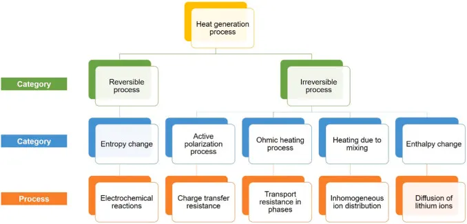
In general, the heat generation within the LIBs at normal temperature is associated with charge transfer and chemical reactions during charging and discharging. The heat is generated either in the reversible process or the irreversible process in LIBs. Fig.3 shows the possible heat generation within LIBs. The heat generated in the reversible process, also known as entropic heat, originates from the reversible entropy change during electrochemical reactions . There are many possible irreversible processes that can generate heat, including active polarization process, ohmic heating process, heating due to mixing and enthalpy change. The polarization is resulted from the overpotential between operating potential and open circuit potential of the batteries. It leads to the increase of charge transfer resistance at electrode-electrolyte interface, or Solid Electrolyte Interface (SEI). When lithium ions overcome such resistance at interface for their intercalation/deintercalation, heat is produced. The ohmic heating process occurs in both the electrode and electrolyte. It is due to the resistance of electrodes and electrolytes that hinders the transportation of charges. When the LIBs are in operation, either in charging or in discharging, the ion distribution becomes inhomogeneous, which can lead to the mixing of ions and the generation of heat during mixing. Another form of irreversible process that generates heat is the enthalpy change due to phase change in cathodes, which is primarily due to the diffusion of lithium ions.
Ageing
Ageing is an effect during the application of LIBs at high temperatures. Ageing not only affects the performance of LIBs but also reduces their lifetime. In general, the ageing of LIBs includes cycle ageing and calendar ageing. These two types of ageing, however, always occur in combination due to the complex composition and working process of LIBs. Increasing the operating temperature of LIBs above the optimal scope will accelerate the ageing process and lead to the degradation of LIBs. Most of the research in this area focuses on the ageing of either the individual components inside the battery or the battery system.
Thermal runaway
Thermal runaway may happen when the batteries are manufactured defectively or handled improperly. Thermal runaway often occurs at high-temperature states, in which the high temperature triggers exothermic reactions in the operating batteries. These reactions release more heat, and in turn, further promote the increase of temperature within the batteries. When such uncontrolled heat generation exceeds the heat endurance of the batteries, fire and exploration would occur. Many notebook manufacturers such as Apple and Lenovo recalled their products and suffered huge financial losses in the past decades due to thermal runaway issues. Hence, understanding the thermal runaway of LIBs is important to the thermal management of batteries at high temperatures.
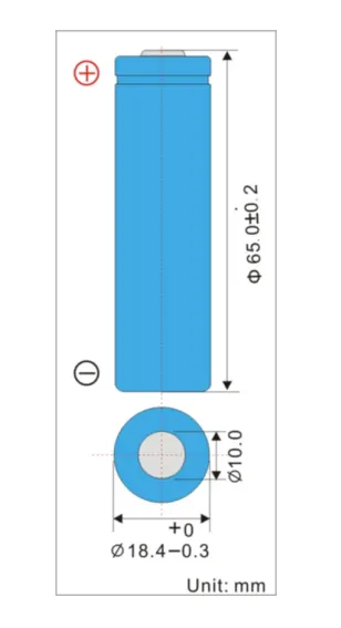
Datasheet of Lithium-ion battery Pack used in Model
Battery Model: LIR18650 2600mAh.
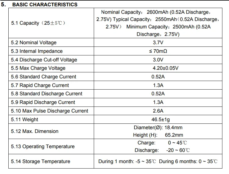
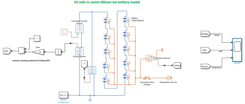
10-cell series lithium-ion battery model
Coulomb Counting Method for finding SOC of battery
The Coulomb counting method measures the discharging current of a battery and integrates the discharging current over time in order to estimate SOC. The coulomb counting method is done to estimate the SOC(t) , which is estimated from the discharging current, I(t), and previously estimated values, SOC(t-1). SOC is calculated by the following equation:

But there are several factors that affect the accuracy of the Coulomb counting method including temperature, battery history, discharge current, and cycle life.
Block used in Model
1.Battery(Table-Based)
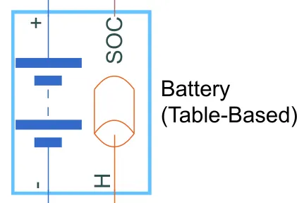
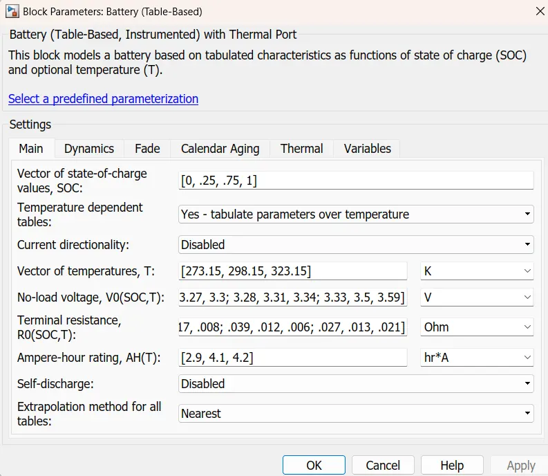
This block models a battery based on tabulated characteristics as functions of the state of charge (SOC) and optional temperature (T).
SOC and Temperature port is activated for the battery and battery parameters are set as per requirement.
2. Controlled Current Source
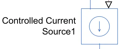
The block represents an ideal current source that is powerful enough to maintain the specified current through it regardless of the voltage across it. The output current is I = Is, where Is is the numerical value presented at the physical signal port.
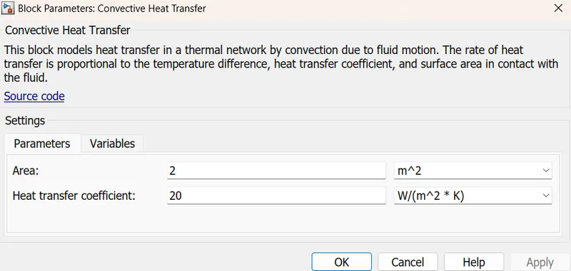
3. Convective Heat Transfer block

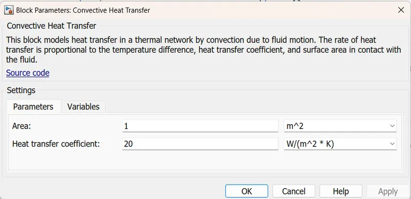
This block models heat transfer in a thermal network by convection due to fluid motion. The rate of heat transfer is proportional to the temperature difference, heat transfer coefficient, and surface area in contact with the fluid.
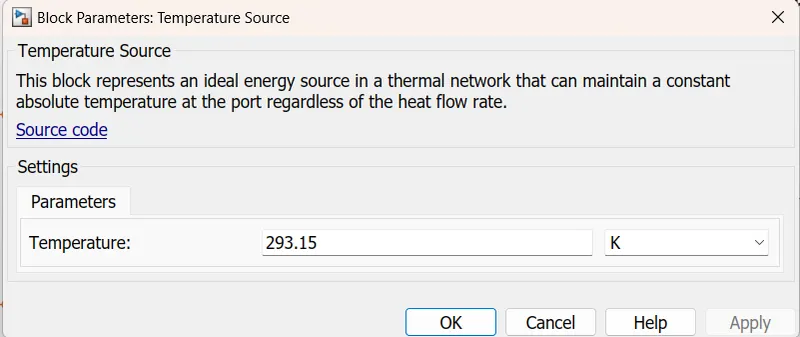
4. Temperature Source
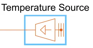
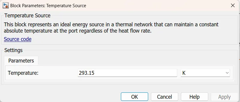
This block represents an ideal energy source in a thermal network that can maintain a constant absolute temperature at the port regardless of the heat flow rate.
5. Temperature Sensor
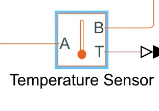
This block measures temperature in a thermal network. There is no heat flow through the sensor. The physical signal port T reports the temperature difference across the sensor. The measurement is positive when the temperature at port A is greater than the temperature at port B.
6. Voltage Sensor
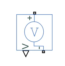
The block represents an ideal voltage sensor, a device that converts voltage measured between any electrical connections into a physical signal proportional to the voltage.
Connections + and - are conserving electrical ports through which the sensor is connected to the circuit. Connection V is a physical signal port that outputs voltage value.
Explanation
- We take the table base battery cell.10 cells connected in series as shown in the model.
- Cells with 100% SOC and temperature of 298.15K.
- Controlled current source is connected in the model as shown in the figure. We have to discharge the battery to SOC of 0%.
- PS constant block supplies the constant current to the controlled current source.
- Measuring the current in the circuit current sensor block is connected in the model as shown in the figure.
- Also connect the Voltage sensor to measure the voltage Across the battery cells.
- Curren sensor output port is connected to the integration block to integrate the current as per the Columb counting method.
- Integrated current is divided by the Ampere rating of the cell and 3600 sec. So we get the value of SOC at that time.
- This SOC value is subtracted from the Initial SOC value i.e. 1 so we get the present SOC of the battery pack.
- Temperature source of 293.15 kelvin is connected to the battery temperature port.
- Temperature source connected to the battery through the convective heat transfer block.
- Here convective heat transfer block is added because the battery is cooled by the natural flow of air.
- Temperature sensor block is connected to measure temperature in the model.
- We study the behaviour of the battery pack for different surface areas in contact with the fluid.
and different source temperature
1st case
Area-2 m^2
Source Temperature-293.15K
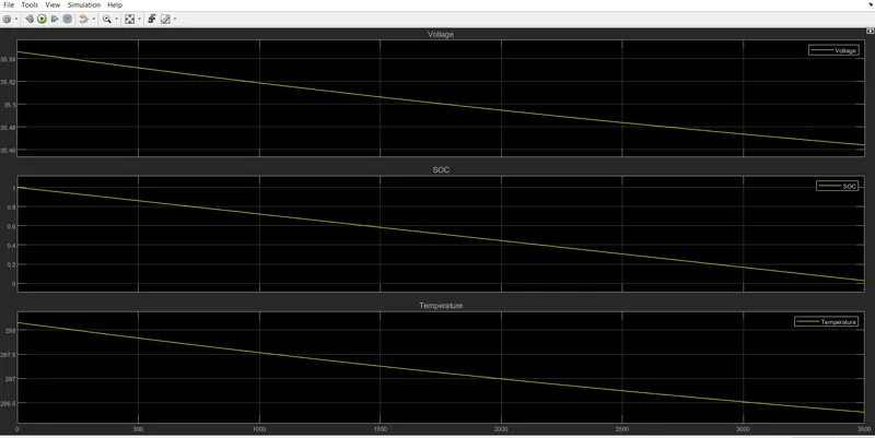
In this case, the initial battery pack temperature is 298.15 k, SOC is 1(100%), and pack voltage is 35.55 volts.
After Simulating the model to 3600 sec we obtain the results.
In this case, the battery pack is discharged to the constant current of 4.2A.
So the voltage of the battery pack decreases to 35.46 volts.
SOC is 0% after simulation and
Temperature decreases to 296.3k.
2nd Case
Area-2 m^2
Source Temperature-300K
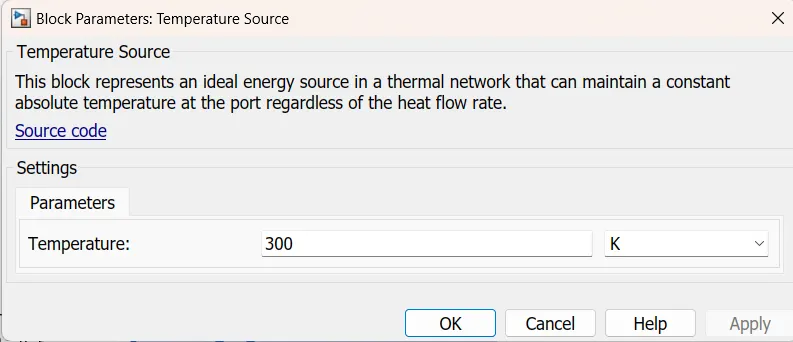
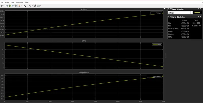
In this case, the initial battery pack temperature is 298.15 k, SOC is 1(100%), and pack voltage is 35.55 volts.
After Simulating the model to 3600 sec we obtain the results.
In this case, the battery pack is discharged to the constant current of 4.2A.
So the voltage of the battery pack increases to 35.58 volts.
SOC is 0% after simulation and
Temperature increase to 298.9k.
3Rd case
Area-2 m^2
Source Temperature-300K
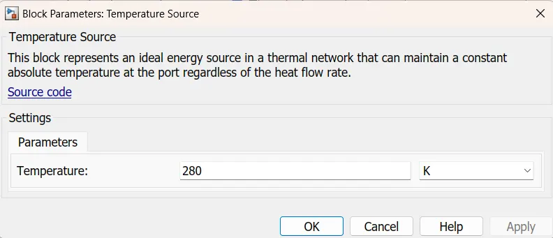
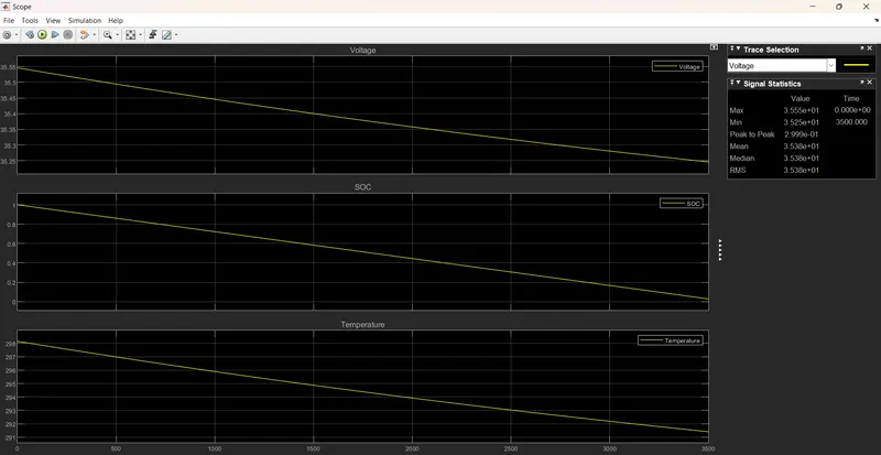
In this case, the initial battery pack temperature is 298.15 k, SOC is 1(100%), and pack voltage is 35.55 volts.
After Simulating the model to 3600 sec we obtain the results.
In this case, the battery pack is discharged to the constant current of 4.2A.
So the voltage of the battery pack decreases to 35.25 volts.
SOC is 0% after simulation and
Temperature decreases to 291.4k.
Case 4
Area-5m^2
Source Temperature-293.15K
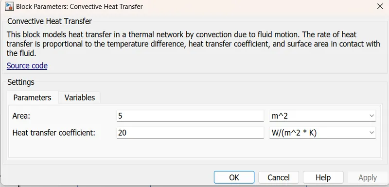
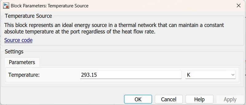
In this case, the initial battery pack temperature is 298.15 k, SOC is 1(100%), and pack voltage is 35.55 volts.
After Simulating the model to 3600 sec we obtain the results.
In this case, the battery pack is discharged to the constant current of 4.2A.
So the voltage of the battery pack decreases to 35.39 volts.
SOC is 0% after simulation and
Temperature decreases to 294.7k.
Case 5
Area-10m^2
Source Temperature-293.15K
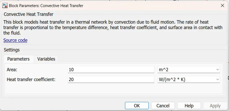
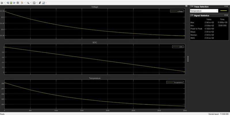
In this case, the initial battery pack temperature is 298.15 k, SOC is 1(100%), and pack voltage is 35.55 volts.
After Simulating the model to 3600 sec we obtain the results.
In this case, the battery pack is discharged to the constant current of 4.2A.
So the voltage of the battery pack decreases to 35.35 volts.
SOC is 0% after simulation and
Temperature decreases to 293.6k.
Conclusion
- We study the various condition of temperature and area of cooling.
- As the temperature of the battery pack increases from the normal temperature the voltage of the pack also increases.
- As the temperature of the pack decreases voltage also decreases.
- Convection area increases for heat transfer temperature of the battery pack decreases rapidly and vice versa.
- AS getting from various conditions Cooling and heating of battery pack is directly proportional to the battery parameters.
- Rapid cooling is done by increasing in the contact area of the battery pack to the heat-transferring strips.
- i.e. battery temperature is well maintained by properly circulating the thermal strips.
Link of Model share below
https://drive.google.com/file/d/1TtNNm-ykZm_tF-zVylWES21RCGu3XR75/view?usp=share_link