Project 2 Thermal modeling of battery pack
AIM :-
To study Thermal modeling of the battery pack with the help of MATLAB and SIMULINK.
OBJECTIVE :-
To model and simulate a 10 cells in series lithium ion battery pack, analyze the thermal effects and compare its life cycle performance at various temperatures, charge & discharge rates using MATLAB.
THEORY
BATTERY PACK:
A battery pack is a set of any number of (preferably) identical batteries or individual battery cells. They may be configured in a series, parallel or a mixture of both to deliver the desired voltage, capacity, or power density. The term battery pack is often used in reference to cordless tools, radio-controlled hobby toys, and battery electric vehicles.
Components of battery packs include the individual batteries or cells, and the interconnects which provide electrical conductivity between them. Rechargeable battery packs often contain a temperature sensor, which the battery charger uses to detect the end of charging. Interconnects are also found in batteries as they are the part which connects each cell, though batteries are most often only arranged in series strings.
When a pack contains groups of cells in parallel there are differing wiring configurations which take into consideration the electrical balance of the circuit. Battery regulators are sometimes used to keep the voltage of each individual cell below its maximum value during charging so as to allow the weaker batteries to become fully charged, bringing the whole pack back into balance. Active balancing can also be performed by battery balancer devices which can shuttle energy from strong cells to weaker ones in real time for better balance. A well-balanced pack lasts longer and delivers better performance.
As we know that the electric vehicle market is gradually increasing. With the growth of an electric vehicle, the growth and interest in Lithium-ion cell are also increasing. The energy source for an electric vehicle is stored in cylindrical cells.
Lithium-ion cells are capable of delivering very high power. Lithium-ion cells are used in aerospace, automotive electric vehicle, mobile devices, medical devices and other electronic devices which is based on these cells. The battery pack is installed in lower-floor of the electric vehicle so that weight may distribute equally and also the centre of gravity also maintain properly.
The high voltage battery pack is one of the most important components of any electric vehicle. The traction battery of an electric vehicle must achieve the following thing:
- Provide maximum traction motor torque
- Vehicle range in sense of kilometre
- To achieve the proper life cycle of battery
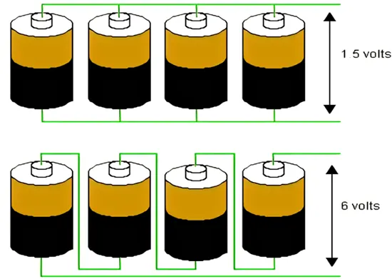
The battery pack of an electric vehicle is generally having a series or parallel combination. Large battery pack have multiple cell modules, in which many numbers of cells are kept together to build a large battery pack. Basically, a series connection is used to compound the voltage whereas the parallel connection is for compound current capacity. A battery cell consists of five major components that are electrodes – anode and cathode, separators, terminals, electrolyte and enclosure.
SERIES AND PARALLEL CONNECTION OF CELLS:
In series, cells are joined end to end so that the same current flows through each cell. In case if the cells are connected in series the emf of the battery is connected to the sum of the emf of the individual cells. Suppose we have multiple cells and they are arranged in such a way that the positive terminal of one cell is connected to the negative terminal of the another and then the negative terminal is connected to the positive terminal and so on, then we can that the cell is connected in series. Cells are in parallel combination if the current is divided among various cells. In a parallel combination, all the positive terminal are connected together and all the negative terminal are connected together.
Component Requirement:
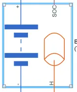
Battery (Table-Based):
Description:
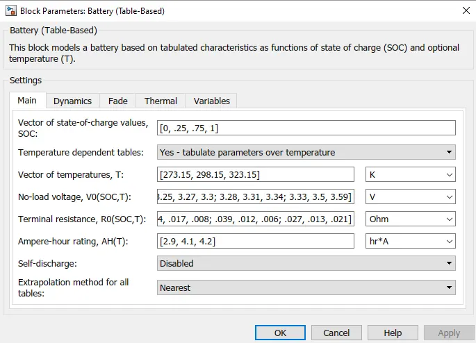
The Battery (Table-Based) block represents a high-fidelity battery model. The block calculates no-load voltage as a function of charge level and optional temperature using lookup tables and includes several modeling options:
Self-discharge
Battery fade
Charge dynamics
Note:
The block can use linear or nearest interpolation and extrapolation for all the table based parameters. For rows and columns, it follows the row-column convention, whereas rows are indexed first and, subsequently, columns.
The plot shows a battery whose performance varies with temperature and state of charge changes, as typically found on a datasheet.
Use this block to parameterize batteries with complex no-load voltage behavior from datasheets or experimental results. For a simpler representation of a battery, see the Battery block.
The Battery (Table-Based) block has four modeling variants, accessible by right-clicking the block in your block diagram and then selecting the appropriate option from the context menu, under Simscape > Block choices:
Uninstrumented | No thermal port — Basic model that does not output battery charge level and simulates at a fixed temperature. This modeling variant is the default.
Uninstrumented | Show thermal port — Model with exposed thermal port. This model does not output internal charge level of the battery.
Instrumented | No thermal port — Model with exposed charge output port. This model uses a fixed temperature throughout the simulation.
Instrumented | Show thermal port — Model that lets you output internal charge level of the battery. Both the thermal port and the charge output port are exposed.
The instrumented variants have an extra physical signal port that outputs the internal state of charge. Use this functionality to change load behavior as a function of state of charge, without the complexity of building a charge state estimator.
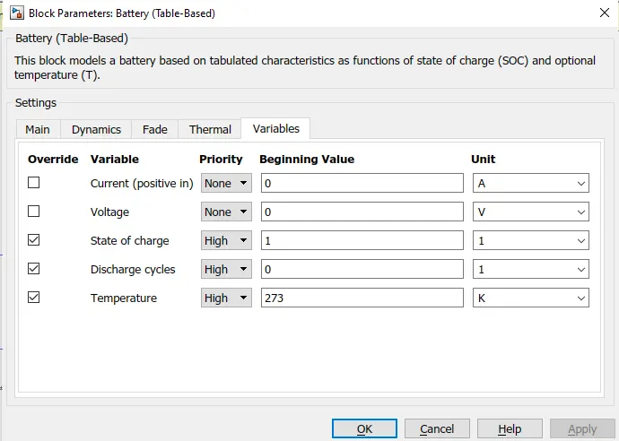
The thermal port variants expose a thermal port, which represents the battery thermal mass.
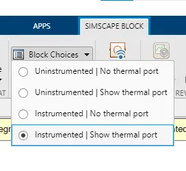
here we have use the Instrumented | show thermal port
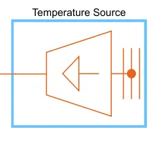
Temperature Source:
Constant source of thermal energy, characterized by temperature expand all in page
Description:
The Temperature Source block represents an ideal source of thermal energy that is powerful enough to maintain specified temperature at its outlet regardless of the heat flow consumed by the system.
The source generates constant absolute temperature, defined by the Temperature parameter value.
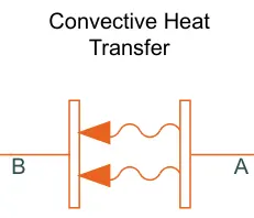
Convective Heat Transfer:
Description:
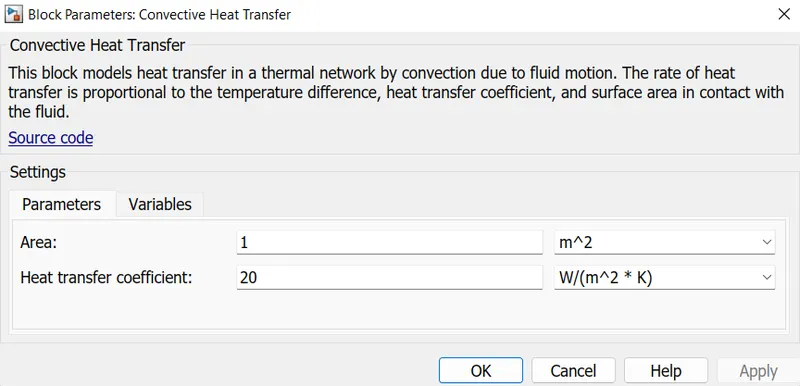
The Convective Heat Transfer block represents a heat transfer by convection between two bodies by means of fluid motion. The transfer is governed by the Newton law of cooling and is described with the following equation:
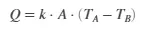
where
Q Heat flow
k Convection heat transfer coefficient
A Surface areaTA,TB Temperatures of the bodies
Connections A and B are thermal conserving ports associated with the points between which the heat transfer by convection takes place. The block positive direction is from port A to port B. This means that the heat flow is positive if it flows from A to B.
Temperature Sensor
Description:
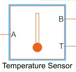
The Temperature Sensor block represents an ideal temperature sensor, that is, a device that determines the temperature differential measured between two points without drawing any heat.
Connections A and B are thermal conserving ports that connect to the two points where temperature is being monitored. Port T is a physical signal port that outputs the temperature differential value.
The block positive direction is from port A to port B. The measured temperature is determined as T = TA – TB.
Ports:
The block has the following ports:
A - Thermal conserving port associated with the sensor positive probe.
B - Thermal conserving port associated with the sensor negative probe.
T - Physical signal output port for temperature.
Controlled Current Source:
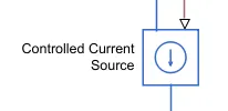
For Discharge the battery with some constant discharge current
Signal Builder :
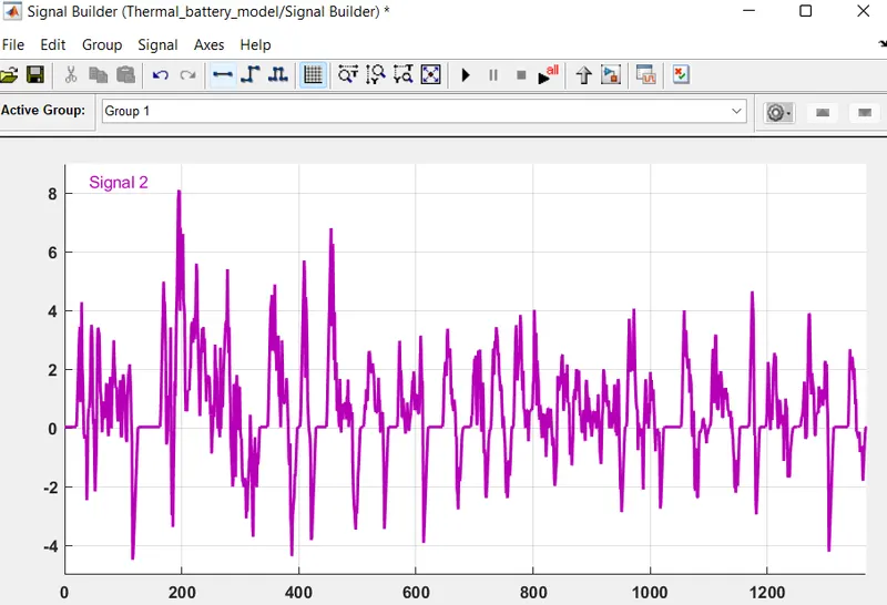
UDDS Cycle is inputed through the signal builder block.
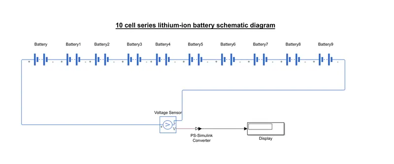
10 cell series lithium-ion battery schematic diagram:
MATLAB MODEL :
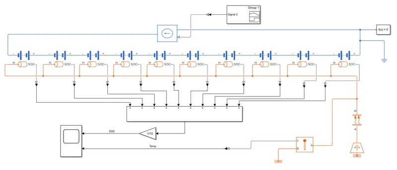
MODEL EXPLANATION:
First connecting the 10 cell(table based) in series. The UDDS cycle is input to the battery by using a signal builder block through controlled current source. Connect the thermal ports on all the Cells, And connect the temperature source to it through connective heat transfer. Temperature sensor taken to the scope from thermal area and is used to take the temperature effect on the battery pack. SOC of each cell is given to the add block through PS-simulink converter, and is taken to the scope.
Then Testing the series batteries with the constant discharge current(3A) on different operating temperatures ranging from 300K, 330K, 360K and 390K.
Temperature Chart:
|
K |
degC |
|
300 |
26.85 |
|
330 |
56.85 |
|
360 |
86.85 |
|
390 |
116.85 |
RESULT :-
The result on 300K temperature:
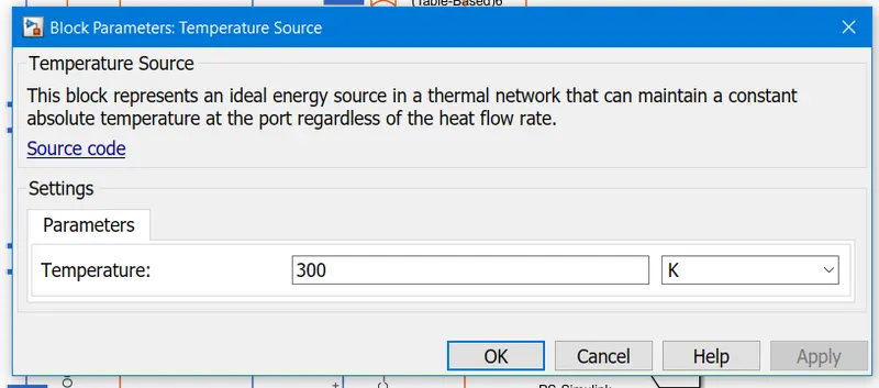
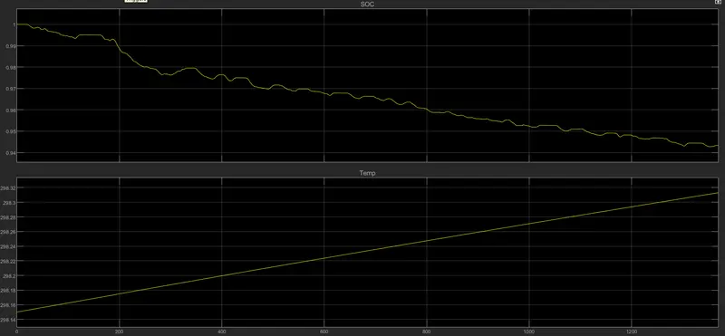
- Here we can see that the battery SOC was reduced to 94.3%(0.943) of the total value and the temperature of the battery pack reached 298.31k
The result on 330K temperature:
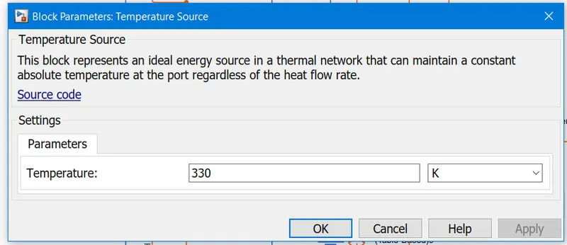
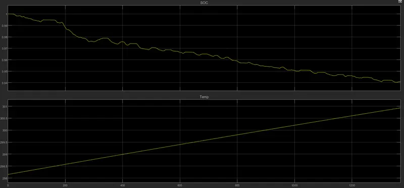
- The temperature source is incresed to 330K, Then the battery SOC was reduced to 94.1%(0.941) of the total value and the temperature of the battery pack reached 300.9k
The result on 360K temperature:
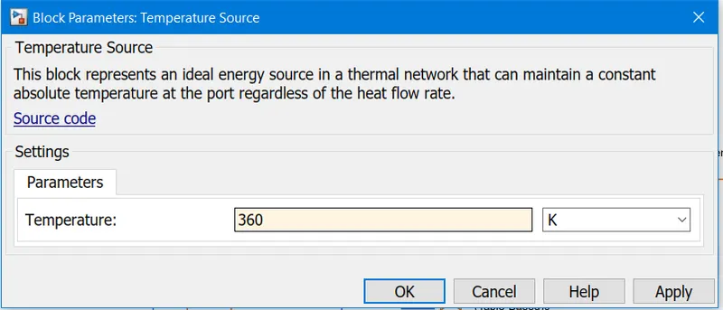
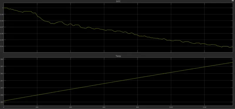
- The temperature source is incresed to 360K, Then the battery SOC was reduced to 93.8%(0.938) and the temperature of the battery pack reached 303.5k
The result on 390K temperature:
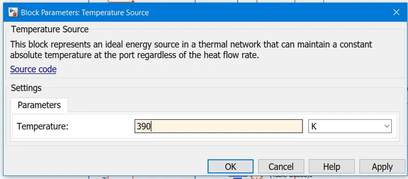
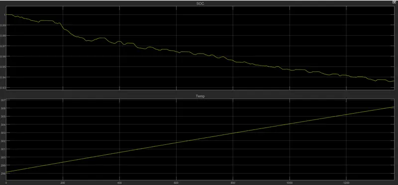
- The temperature source is incresed to 390K, Then the battery SOC was reduced to 93.6%(0.936) and the temperature of the battery pack reached 306.2k
Comments:
|
Temp source(K) |
degC |
SOC% |
Temp of the battery pack |
|
300 |
26.85 |
94.3% |
298.31k |
|
330 |
56.85 |
94.1% |
300.9k |
|
360 |
86.85 |
93.8% |
303.5k |
|
390 |
116.85 |
93.6% |
306.2k |
As we can see, with the rise in temperature, the SOC decreases which means that if we operate the battery at a high temperature than the rated temperature then the battery will discharge fast and the life of the battery will decrease accordingly. And also temperature of the battery pack is increased when temperature source increases.
CONCLUSION:
Studied Thermal modeling of the battery pack with the help of MATLAB and SIMULINK