Project 2 Thermal modeling of battery pack
Thermal Modeling of Battery Pack:
Aim of the Project:
For a 10 cell series lithium ion battery model, simulate the thermal effects and compare life cycle performance at various temperatures, charge & discharge rates using MATLAB.
OBJECTIVE:
Create a simulink model using simscape blockset.10 lithium ion cell connected in series. Determined the charge & discharge characteristics of the fully charged battery. Perform various temperature condition and compare with life cycle of the battery.
Abstract:
Simulink Model:
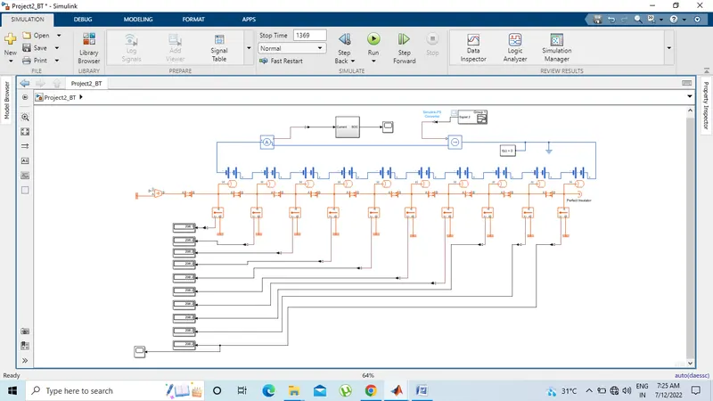
Model Description:
Battery(Table Based):
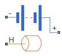
Library: Simscape / Electrical / Sources
The Battery (Table-Based) block represents a high-fidelity battery model. The block calculates no-load voltage as a function of charge level and optional temperature using lookup tables and includes several modeling options:
- Self-discharge
- Battery fade
- Charge dynamics
- Calendar aging
The Battery (Table-Based) block has four modeling variants, accessible by right-clicking the block in your block diagram and then selecting the appropriate option from the context menu, under Simscape > Block choices:
- Uninstrumented | No thermal port— Basic model that does not output battery charge level and simulates at a fixed temperature. This modeling variant is the default.
- Uninstrumented | Show thermal port— Model with exposed thermal port. This model does not output internal charge level of the battery.
- Instrumented | No thermal port— Model with exposed charge output port. This model uses a fixed temperature throughout the simulation.
- Instrumented | Show thermal port— Model that lets you output internal charge level of the battery. Both the thermal port and the charge output port are exposed.
The instrumented variants have an extra physical signal port that outputs the internal state of charge. Use this functionality to change load behavior as a function of state of charge, without the complexity of building a charge state estimator. The thermal port variants expose a thermal port, which represents the battery thermal mass.
We select Uninstrumented| Show thermal port battery for this simscape model. Understanding about battery thermal condition during discharge.
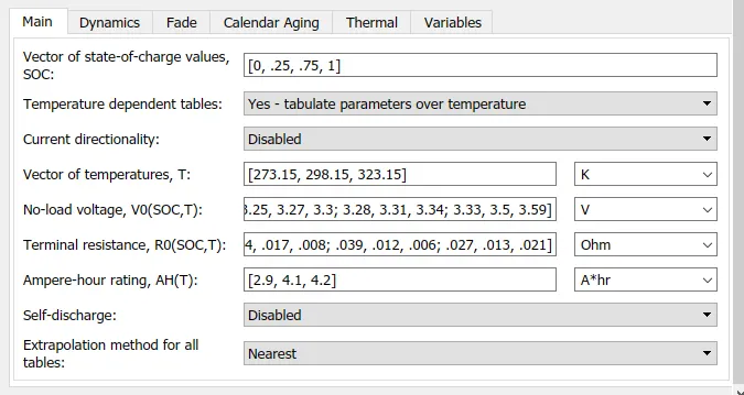
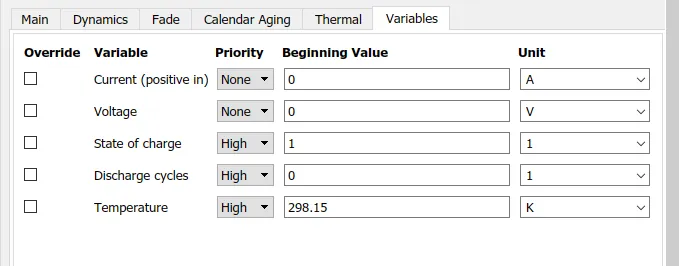
Battery Parameters:
Temperature Sensor:

- The Temperature Sensorblock represents an ideal temperature sensor, that is, a device that determines the temperature differential measured between two points without drawing any heat.
- Connections A and B are thermal conserving ports that connect to the two points where temperature is being monitored. Port T is a physical signal port that outputs the temperature differential value.
The block positive direction is from port A to port B. The measured temperature is determined as T = TA – TB.
The block has the following ports:
A: Thermal conserving port associated with the sensor positive probe.
B: Thermal conserving port associated with the sensor negative probe.
T: Physical signal output port for temperature.
Convective Heat Transfer:
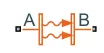
The Convective Heat Transfer block represents a heat transfer by convection between two bodies by means of fluid motion. The transfer is governed by the Newton law of cooling and is described with the following equation: Q=k·A·(TA−TB)
where
|
Q |
Heat flow |
|
k |
Convection heat transfer coefficient |
|
A |
Surface area |
|
TA,TB |
Temperatures of the bodies |
Connections A and B are thermal conserving ports associated with the points between which the heat transfer by convection takes place. The block positive direction is from port A to port B. This means that the heat flow is positive if it flows from A to B.
The block has the following ports:
A: Thermal conserving port associated with body A.
B: Thermal conserving port associated with body B.
Parameters:
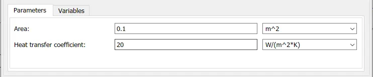
Controlled Temperature: Source:
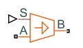
The Temperature Source block represents an ideal source of thermal energy that is powerful enough to maintain specified temperature at its outlet regardless of the heat flow consumed by the system.The source generates constant absolute temperature, defined by the Temperature parameter value.
Controlled Current Source:
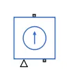
The Controlled Current Source block represents an ideal current source that is powerful enough to maintain the specified current through it regardless of the voltage across the source.The output current is I = Is, where Is is the numerical value presented at the physical signal port.The positive direction of the current flow is indicated by the arrow.
Current Sensor:

The Current Sensor block represents an ideal current sensor, that is, a device that converts current measured in any electrical branch into a physical signal proportional to the current.
Connections + and – are electrical conserving ports through which the sensor is inserted into the circuit. Connection I is a physical signal port that outputs the measurement result.
Perfect Insulator:

This block represents a terminus in a thermal network with no heat flow and no energy storage. Use this block as an insulation for thermal conserving ports to prevent heat exchange with the environment and to model an adiabatic process. This block can also be used to set an initial value and priority for the temperature at the connected port.
SOC Estimation:
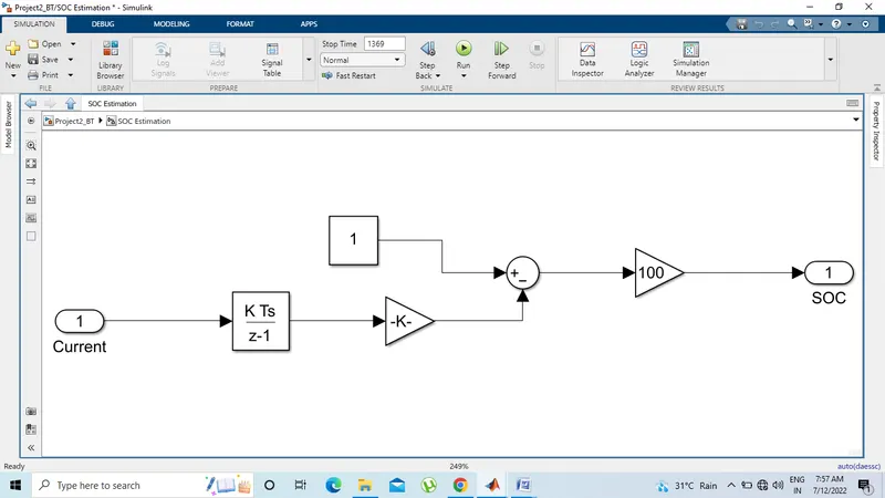
- This is SOC estimation subsystem block. First I connected current as a inport block.
- Then I have connected discrete time integrator block.Discrete-time integration or accumulation of the input signal.
- Connect gain block for convert the coulombs value to physical value. Gain block parameters is 1/(50*3600).
- Use sum block for Add or subtract inputs. Specify one of the following.
- Use another gain for battery charge value. Battery fully charged that’s why 100.
- Connect one output block for soc.
Signal Builder:
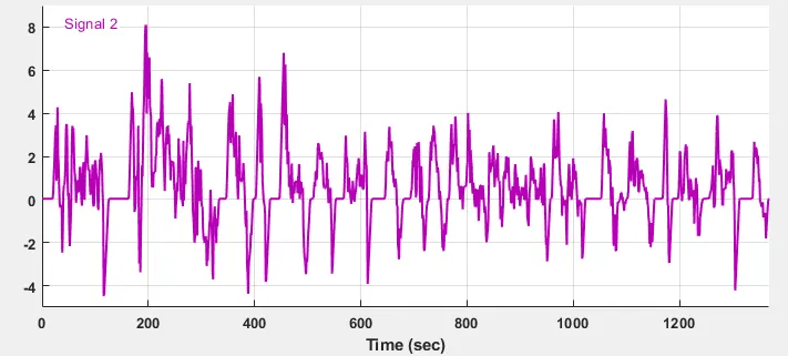
The Signal Builder block allows you to create interchangeable groups of piecewise linear signal sources and use them in a model. You can quickly switch the signal groups into and out of a model to facilitate testing. In the Signal Builder window, create signals and define the output waveforms.To open the window, double-click the block. I used UDDS spreadsheet for understand the charge discharge characteristic.
Result:
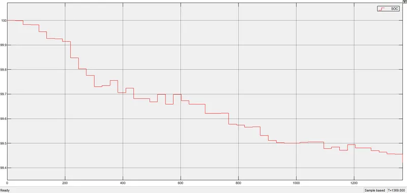
This is SOC % graph. After 1369sec simulation soc% is 99.4. due to charge and discharge condition battery did not fully discharged. In this graph I saw some period time battery charge up and some period of time battery discharge.
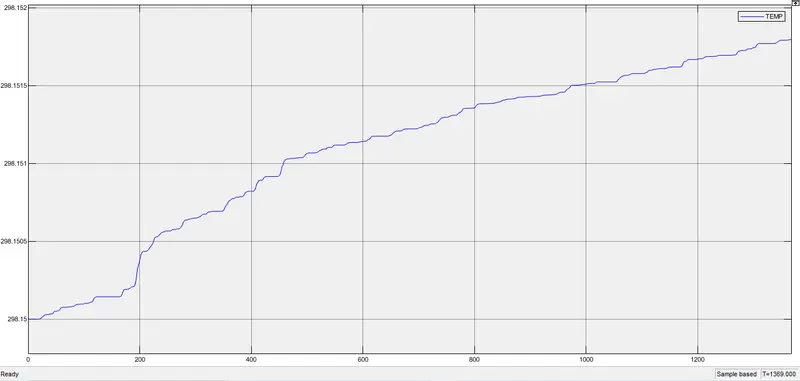
This is temperature graph. After 1369sec simulation temperature increase 298.15 to 298.16. this is small change of the temperature. Battery default temperature is 298.15 K.
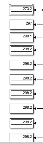
Displayed all the individual battery temperature. All the battery temperature is same.
Case 2:
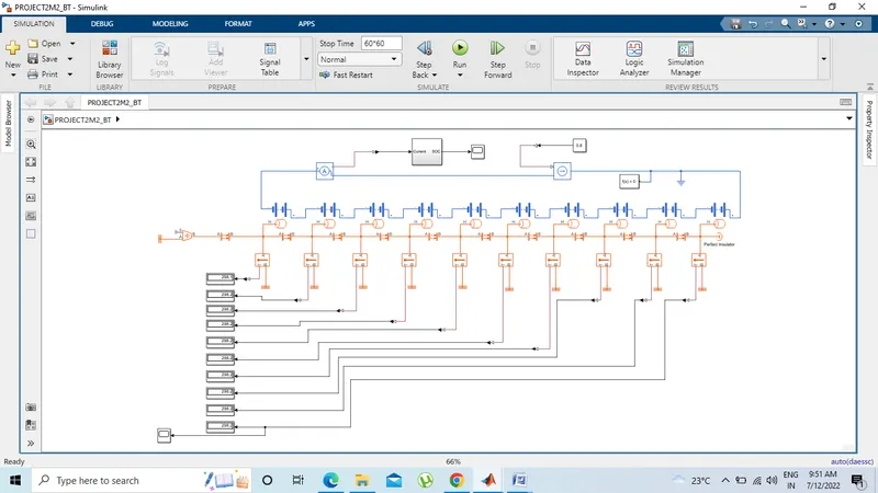
In this model I have connected one constant block value is 0.8.
Result:
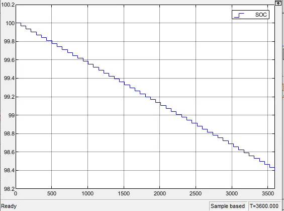
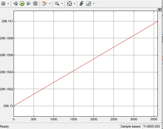
In this condition soc decrease up to 98.6%. and temperature increase upto 298.16 K. this model simulated 3600 sec.
Conclusion:
- The ambient temperature increase provided by temperature source is 298.15K.
- SOC% decrease up to 98% after 1369 sec simulation.
- All the battery initial temperature is 298.15 K. After simulation only .15% changes.