Project 2 Thermal modeling of battery pack
OBJECTIVE :-
For a 10 cell series lithium ion battery model, simulate the thermal effects and compare life cycle performance at various temperatures, charge & discharge rates using MATLAB.
THEORY:-
Now mostly lithium ion batteries are used in electric vehicles and we should know the charging and discharging rate to operate the battery efficiency and also the temperature rating of battery to remain in healthy position. Here we simulate the thermal effect of this lithium ion cell by knowing how much temperature rise will take place so that we can provide efficient cooling to the battery as its increases its life cycle .
This model shows how to simulate the battery pack consisting of multiple series connected cell in an efficient manner. This also shows how a fault can be introduced into one cells to see the impact on battery performance and cell temperature efficiency.
SIMULATIONS :-
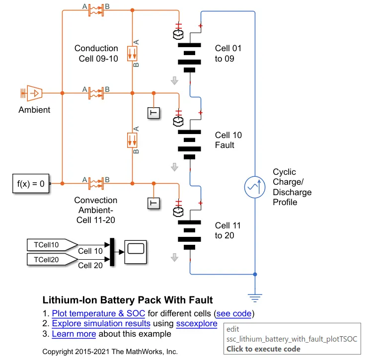
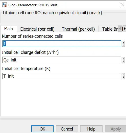
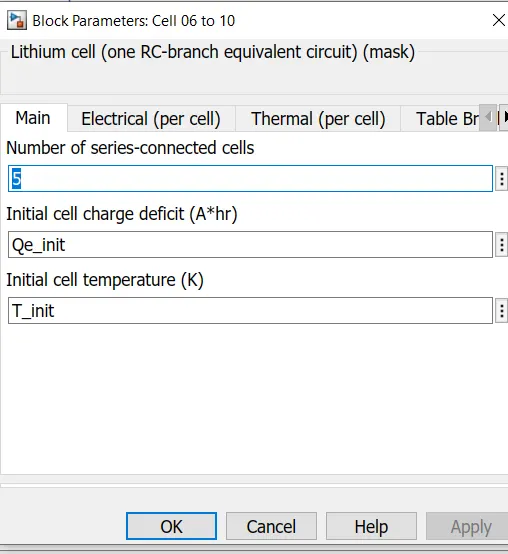
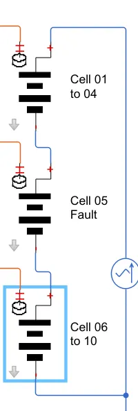
As here we can see that in this model the lithum cellsa re connected in series. The 10th cell in the battery pack is considered as faulty.
The fault is represented by changing the parameters for the cell 10 reducing both capacity and open circuit voltage and increaseing the reistance value.
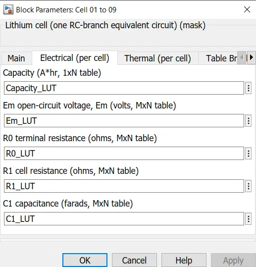
We can see that cells are working at its full potential.
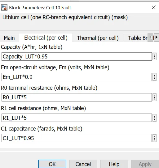
Here we can see that capacity is multilied by 0.95 , thus it means that capacity is reduced by 5%.
The open circuit voltage is multilied by 0.9 , thus it means that open circuit voltage is reduced by 10%.
Like that cell resistance is also multiplied by factor 5 times , thus it means that cell resistance is increased by 5 times and as resistance increases tempertaure also increases.
In the model their is a convective heat transfer from battery pack to surroundings environment and there if conduction heat transfer between the cells of battery pack.
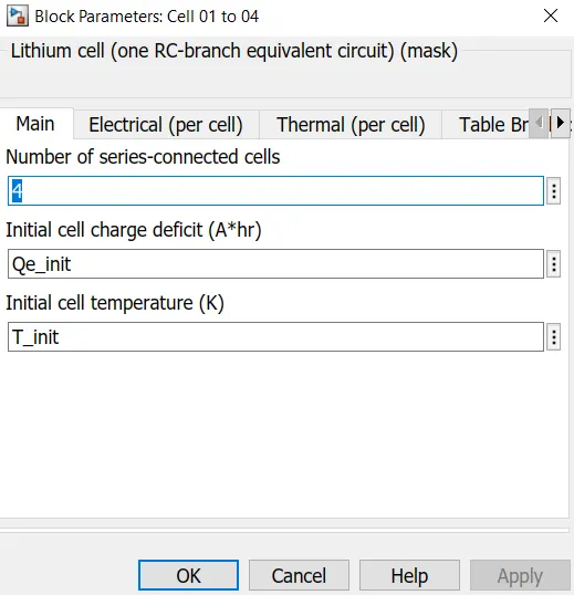
It is mentioned that 10 cell series lithium battery thus we have to mke some changes over here.
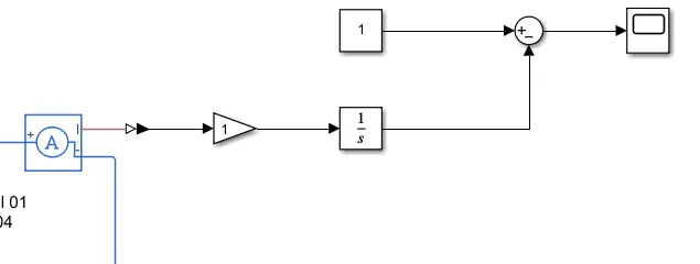
To estimate SOC :-
To estimate tempertaure :-
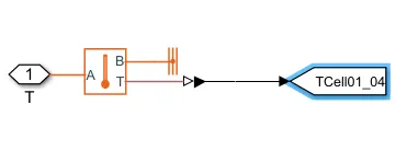
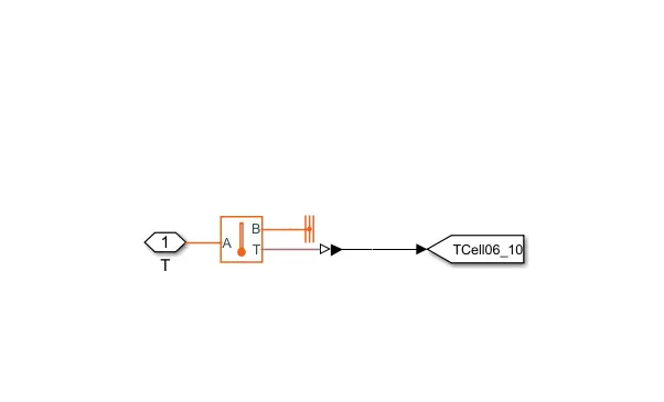
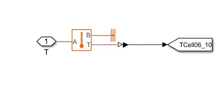
Here in the sub system we have used a temperature sensor block where point A is connected to temperature port and B point is connected to thermal reference. Port T is connected to goto block where as its from block is connected with a mux and then connetced to a cope block to see the results .
Overall model looks like :-
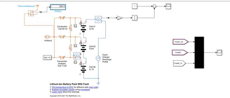
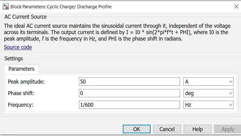
From the parameter we can see that The peak amplitude voltage of the ac current source is 50 Amp and we considered phase shift as 0 , frequency is considered as 1/6000 Hz.
RESULTS:-
Here we simulate the model for 7200 seconds ;
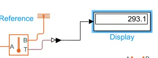
1. The displays shows the ambient temperature :-
2.Temperature of cells :-
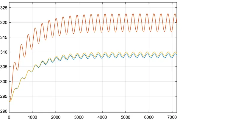
Thus from this results we can say that faulty cells have higher temperaturethan normal cell and the normal temperature is 295K to 325K.
3.State of charge (SOC) :-
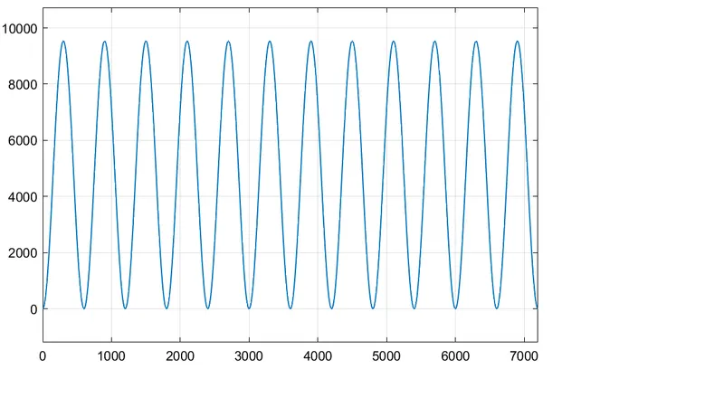
We found that SOC graph is fluctuating during the entire time of simulations . Here we can also considered as 6 cycles for 3600 sec (1 Hr). This lify cycle can be increased if we remove the faulty cells.
CONCLUSIONS:-
Thus in the above case we found that if the faulty cell is there it decreases the battery life cycle and temperature of faulty cells is much higher than normal working cells and because of this thermal condition efficiency of battery pack will get reduced.