Project 2 - Rankine cycle Simulator
AIM :
To write a code in MATLAB to Create a Rankine Cycle Simulator to calculate the state points of the Rankine Cycle and plot the corresponding T-s and h-s plots for the given set of inputs.
Objectives :
Understand the concept of Rankine cycle by referring to standard thermal engineering text book.
- Create a Rankine Cycle Simulator using MATLAB.
- Your code should calculate the state points of the Rankine Cycle (any type of your choice) based on user inputs.
- Then, plot the corresponding T-s and h-s plots for the given set of inputs. Title and axes labels are a must, while legends could be used if necessary.
- The presentation of your code will be taken into consideration while grading. Labelling sections of your code using comments is appreciated.
- Attach a report explaining the working of a rankine cycle simulator and also the research done by you.
Theory:
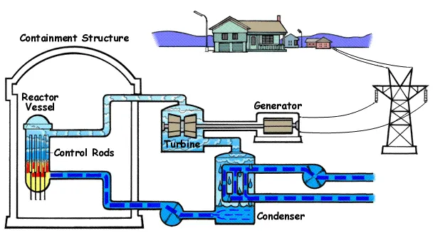
The Rankine cycle or Rankine Vapor Cycle is the process widely used by power plants such as coal-fired power plants or nuclear reactors. In this mechanism, a fuel is used to produce heat within a boiler, converting water into steam which then expands through a turbine producing useful work. This process was developed in 1859 by Scottish engineer William J.M. Rankine.[1] This is a thermodynamic cycle which converts heat into mechanical energy—which usually gets transformed into electricity by electrical generation.
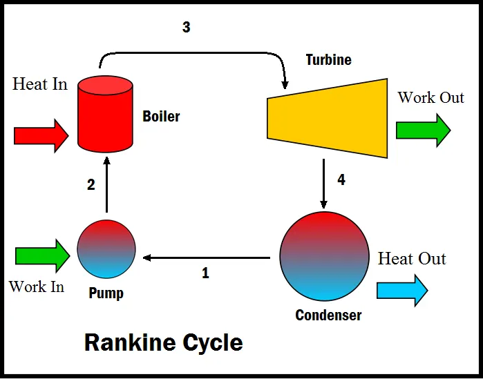
Figure 1. A simple schematic with components for the Rankine Cycle.
The steps in the Rankine Cycle as shown in Figure 1 and the corresponding steps in the pressure volume diagram (figure 2) are outlined below: [1]
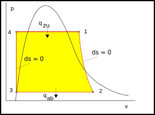
Figure 2. The pressure volume diagram of the Rankine cycle. This illustrates the changes in pressure and volume the working fluid (water) undergoes to produce work.
- Pump: Compression of the fluid to high pressure using a pump (this takes work) (Figure 2: Steps 3 to 4)
- Boiler: The compressed fluid is heated to the final temperature (which is at boiling point), therefore, a phase change occurs—from liquid to vapor. (Figure 2: Steps 4 to 1)
- Turbine: Expansion of the vapor in the turbine. (Figure 2: Steps 1 to 2)
- Condenser: Condensation of the vapor in the condenser (where the waste heat goes to the final heat sink (the atmosphere or a large body of water (ex. lake or river). (Figure 2: Steps 2 to 3)
The efficiency of the Rankine cycle is limited by the high heat of vaporization by the fluid. The fluid must be cycled through and reused constantly, therefore, water is the most practical fluid for this cycle. This is not why many power plants are located near a body of water—that's for the waste heat.
As the water condenses in the condenser, waste heat is given off in the form of water vapour—which can be seen billowing from a plant's cooling towers. This waste heat is necessary in any thermodynamic cycle. Due to this condensation step, the pressure at the turbine outlet is lowered. This means the pump requires less work to compress the water—resulting in higher overall efficiencies.
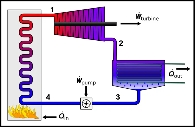
BASIC RANKINE:
Processes and Working :
There are four processes in the rankine cycle :
- Process 1-2 : Isentropic Expansion in the turbine
- Process 2-3 : Constant pressure Heat rejection in condenser
- Process 3-4 : Isentropic compression in the pump
- Process 4-1 : Constant pressure heat addition in the boiler
Rankine cycle efficiency ηR is -

Back Work Ratio:
The fraction of the work produced by the turbine that is consumed by the compressor.
BW ratio=Wp/Wt
Water enters the pump at state 1 as saturated liquid and is compressed isentropically to the operating pressure of the boiler. The water temperature increases somewhat during this isentropic compression process due to a slight decrease in the specific volume of water. The vertical distance between states 1 and 2 on the T-s diagram is greatly exaggerated for clarity.
Water enters the boiler as a compressed liquid at state 2 and leaves as a superheated vapours at state 3. The boiler is basically a large heat exchanger where the heat originating from combustion gases, nuclear reactors, or other sources is transferred to the water essentially at constant pressure. The
boiler, together with the section where the steam is superheated (the superheater), is often called the steam generator.
The superheated vapours at state 3 enters the turbine, where it expands isentropically and produces work by rotating the shaft connected to an electric generator. The pressure and the temperature of steam drop during this process to the values at state 4, where steam enters the condenser. At this
state, steam is usually a saturated liquid–vapour mixture with a high quality. Steam is condensed at constant pressure in the condenser, which is basically a large heat exchanger, by rejecting heat to a cooling medium such as a lake, a river, or the atmosphere. Steam leaves the condenser as saturated liquid and enters the pump, completing the cycle. In areas where water is precious, the power plants are cooled by air instead of water. This method of cooling, which is also used in car engines, is called dry cooling.
Remembering that the area under the process curve on a T-s diagram represents the heat transfer for internally reversible processes, we see that the area under process curve 2-3 represents the heat transferred to the water in the boiler and the area under the process curve 4-1 represents the heat rejected in the condenser. The difference between these two is the net work produced during the cycle.
All the four components of Rankine cycle are steady flow devices hence the process regarding this device can be evaluated as steady state process. The steady state flow energy equation per unit mass of steam reduces to:

The boiler and condenser are not involved in any mechanical work whereas pump and turbine are assumed to isentropic in nature while working throughout the cycle, then conservation of energy relation for each device can be expressed as:
W pump = h2 - h1
Where,
h1 = hj at P1. and v1 = vj at P1
The heat added in boiler can be given as:
qIn = h3 - h2
The work which can be taken out of cycle from turbine is given as:
Wout = h3 - h4
The heat removed from the condenser is given as:
qout = h4 - h1
The thermal efficiency of Rankine cycle is given as:
η th = WNet / qIn. = 1-(qout / qIn )
Where,
WNet = qIn - qout = Wturb - WPump
MATLAB PROGRAM FOR RANKINE CYCLE SIMULATOR
clear all
close all
clc

disp(' RANKINE CYCLE ');
disp('1-2 is Constant pressure heat addition in the boiler');
disp('2-3 is Isentropic Expansion in the Turbine');
disp('3-4 is Constant pressure heat removal in the Condenser');
disp('4-1 is Isentropic compression in the pump');

p1 = input('nValue of Turbine Inlet Pressure, p1(in bar) = ');
T1 = input('nValue of Turbine Inlet temperature, T1(in °.C) = ');
p2 = input('nValue of Turbine Outlet Pressure/Condenser Inlet Pressure, p2(in bar) = ');


% At State 1
h1 = XSteam('h_pT', p1, T1);        % Extracting Enthalpy at state Pt1
s1 = XSteam('s_pT', p1, T1);        % Similarly

% At State 2
s2 = s1;                            % Isentropic Expansion
sf2= XSteam('sL_p', p2);            % Saturated Liquid Entropy
sg2 = XSteam('sV_p', p2);           % Saturated Vapour Entropy
x2 = (s2-sf2)/(sg2-sf2);
hf2 = XSteam('hL_p', p2);
hg2 = XSteam('hV_p', p2);
h2 = hf2 + (x2*(hg2-hf2));

% At State 3
p3 = p2;                            % Constant pressure Heat rejection in Condenser
s3= XSteam('sL_p', p3);
h3 = XSteam('hL_p', p3);

% At State 4
s4 = s3;
p4 = p1;

% Work done by turbine
Wt = h1 - h2;

% Work done to run pump
v3 = XSteam('vL_p', p3);
Wp = v3*(p4 - p3)*100;
h4 = h3 + Wp;

%Net work
Wnet = Wt - Wp;

%Heat into the system
Qin = h1 - h4;

%Heat out of the system
Qout = h2 - h3;

%Thermal efficiency
thermal_eff = (Wnet/Qin)*100;

%Specific Steam Consumption
%SSC = mass flow rate/power
SSC = (3600/Wnet);

% Back Work ratio
BW = (Wp/Wt)


% Calculation of Temperatures at the state points
T3 = XSteam('Tsat_p', p3);
T2 = T3;
Cp4 = XSteam('Cp_ps', p4, s4);
Cv4 = XSteam('Cv_ps', p4, s4);
k = Cp4/Cv4;
T4 = T3/((p3/p4)^((k-1)/k));

%Calculating Temperature, Entropy and Enthalpy at the vapour and liquid line for plotting
T6 = XSteam('Tsat_p', p1);
s5 = XSteam('sL_p', p1);
s6 = XSteam('sV_p', p1);
h5 = XSteam('hL_p', p1);
h6 = XSteam('hV_p', p1);
T5 = T6;


%Plotting the saturation curve
T = linspace(1,375,1000);
for i = 1:length(T)

sf(i) = XSteam('sL_T', T(i));
sg(i) = XSteam('sV_T', T(i));
hf(i) = XSteam('hL_T', T(i));
hg(i) = XSteam('hV_T', T(i));
end

%Plotting T-s diagram
figure(1)
hold on
plot(sf, T, 'b','linewidth',2)
plot(sg, T, 'b','linewidth',2)
plot([s1 s2], [T1 T2], 'r', 'linewidth', 2)
plot([s2 s3], [T2 T3] ,'r', 'linewidth', 2)
plot([s3 s4], [T3 T4], 'r', 'linewidth', 2)
plot([s4 s5], [T4 T5], 'r', 'linewidth', 2)
plot([s5 s6], [T5 T6], 'r', 'linewidth', 2)

sc1 = linspace(s6, s1, 1000);
for l = 1:length(sc1)
 Tc1(l) = XSteam('T_ps', p1, sc1(l));
end
plot(sc1, Tc1, 'r', 'linewidth', 2)
text(s1+0.1, T1,'1','Color','red','FontSize',14)
text(s2+0.1, T2, '2','Color','red','FontSize',14)
text(s3, T3-20, '3','Color','red','FontSize',14)
text(s4, T4+20, '4','Color','red','FontSize',14)
title('Temp V/S Entropy plot','FontSize',14)
xlabel('Entropy ,S (Kj/kgk','FontSize',14)
ylabel('Temperature (°C) ','FontSize',14)
legend('Saturation Curve','FontSize',14)


%Plotting h-s diagram
figure(2)
hold on
plot(sf, hf, 'b', 'linewidth', 2)
plot(sg, hg, 'b',  'linewidth', 2)
plot([s1 s2], [h1 h2], 'r', 'linewidth', 2)
plot([s2 s3], [h2 h3], 'r', 'linewidth', 2)
plot([s3 s4], [h3 h4], 'r', 'linewidth', 2)

hc = linspace(h4, h5, 100);
for r = 1:length(hc)
sch(r) = XSteam('s_ph', p1, hc(r));
end
plot(sch,hc, 'r', 'linewidth', 2)
plot([s5 s6], [h5 h6], 'r', 'linewidth', 2)

for m = 1:length(sc1)
hc1(m) = XSteam('h_ps', p1, sc1(m));
end
plot(sc1, hc1, 'r', 'linewidth', 2)
text(s1+0.1, h1, '1','Color','red','FontSize',14)
text(s2+0.1, h2, '2','Color','red','FontSize',14)
text(s3, h3-100, '3','Color','red','FontSize',14)
text(s4, h4 +200, '4','Color','red','FontSize',14)
title('Enthalpy V/S Entropy plot','FontSize',14)
xlabel('Entropy , S (KJ/kgk)','FontSize',14)
ylabel('Enthalpy , H (KJ/kg)','FontSize',14)
legend('Saturation Curve','FontSize',14','location','northwest')


% Displaying the Results in the Command Window:
disp('Results');
p1 = p1;
T1 = T1;
p2 = p2;
disp('At stage point 1');
n1 = sprintf('P1 is %.3f bar',p1);
disp(n1);
n2 = sprintf('T1 is %.3f C',T1);
disp(n2);
n3 = sprintf('h1 is %.3f kJ/kg',h1);
disp(n3);
n4 = sprintf('s1 is %.3f kJ/kgK',s1);
disp(n4);
disp('At stage point 2');
n11 = sprintf('P2 is %.3f bar',p2);
disp(n11);
n21 = sprintf('T2 is %.3f C',T2);
disp(n21);
n31 = sprintf('h2 is %.3f kJ/kg',h2);
disp(n31);
n41 = sprintf('s2 is %.3f kJ/kgK',s2);
disp(n41);
disp('At stage point 3');
n12 = sprintf('P3 is %.3f bar',p3);
disp(n12);
n22 = sprintf('T3 is %.3f C',T3);
disp(n22);
n32 = sprintf('h3 is %.3f kJ/kg',h3);
disp(n32);
n42 = sprintf('s3 is %.3f kJ/kgK',s3);
disp(n42);
disp('At stage point 4');
n13 = sprintf('P4 is %.3f bar',p4);
disp(n13);
n23 = sprintf('T4 is %.3f C',T4);
disp(n23);
n33 = sprintf('h4 is %.3f kJ/kg',h4);
disp(n33);
n43 = sprintf('s4 is %.3f kJ/kgK',s4);
disp(n43);
n14 = sprintf('Wt is %.3f kJ/kg',Wt);
disp(n14);
n15 = sprintf('Wp is %.3f kJ/kg',Wp);
disp(n15);
n16 = sprintf('Wnet is %.3f kJ/kg',Wnet);
disp(n16);
n17 = sprintf('Thermal_efficiency is %.2f Percent',thermal_eff);
disp(n17);
n18 = sprintf('SSC is %.2f kg/kWh',SSC);
disp(n18);
n19 = sprintf('Back work ratio is %.5f ',BW);
disp(n19);
Explanation of Program
Required Inputs:
Turbine Inlet temperature = 400° C
Turbine Inlet Pressure = 30 bars
Turbine Outlet Pressure = 0.05 bars = Condenser Inlet Pressure
- Xsteam data is used to extract steam and water properties of enthalpy , entropy at specific pressure and temperatures for sat liquid, sat vapour conditions etc .
- The program requires the input of Turbine Inlet Pressure, p1 ( 30 in bar) at state point 1 ( turbine inlet) , Turbine Inlet Pressure (400° Celsius) and pressure at condenser inlet (point 2) ( 0.05 in bar).
- With the help of these input data & from Xsteam data, the program calculates all the state points of the Rankine cycle .
- The Xsteam data works as , h1 = XSteam('h_pT' , p1 , T1) it returns the enthalpy of water at given pressure and temperature in bar and °C respectively.
- As we extract the data , we use thermodynamic relation to further find state points and extract their data from XSteam which are mentioned after studying the Rankine cycle.
- Sf and sg , hf and hg , where f and g stands for saturated liquid and saturated vapour respectively are calculated after studying the plots of Rankine cycles and extracting data from Xsteam file.
- The net work , work done by turbine , work done to run the pump , Heat in and heat out are calculated using standard thermodynamic relation
- Efficiency and Specific steam consumption (s.s.c) of the Rankine cycle is calculated from thermodynamic relations and mentioning them in program using relations.
- T , s and h are extracted at vapour and liquid line for plotting purpose , after 4th point for the variation you observe in the plot .
- Saturation curve is plotted in red for saturated liquid and saturated gas in T-S and in H-S it is black .
- Plot of T v/s s and h v/s s is created from all the points obtained from the program using the plot command and mentioning all the labels, linewidth, color and title.
- The plot changes as the user input changes for the above mentioned inputs .
- Results are displayed in the command window by using sprint command .
Calculate the followings,
- Net work output
- Back work ratio
RESULTS and PLOTS
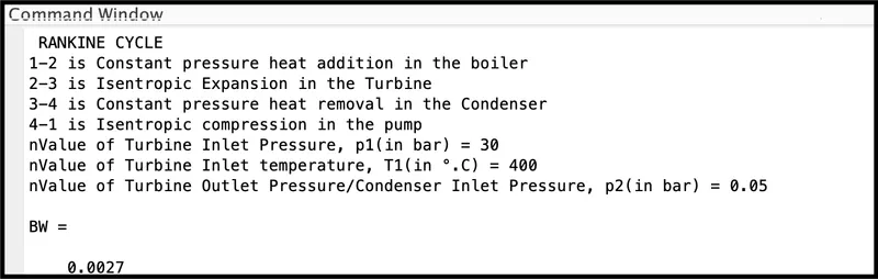
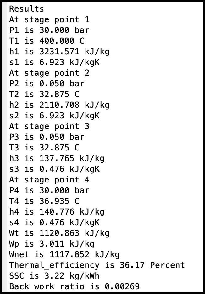
The T-S and H-S performance curves of the Rankine Cycle were plotted.
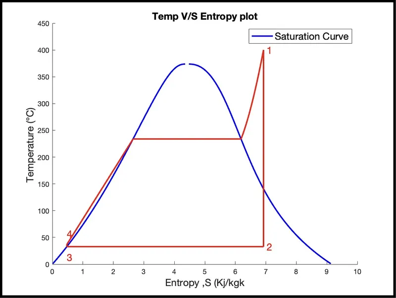
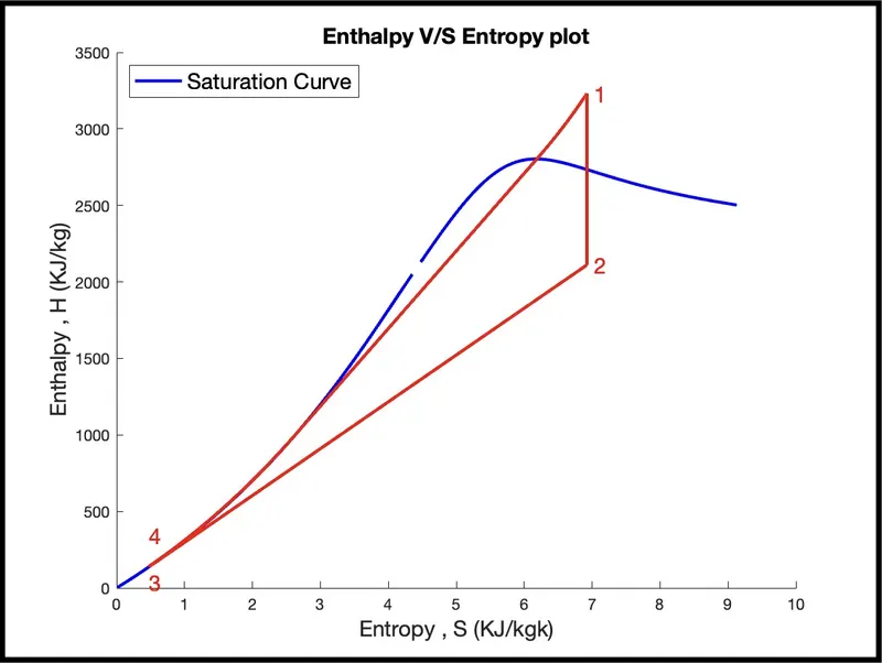
CONCLUSION:
On successful calculating net work output 1117.852 kJ/kg from XSteam
Data file, variation of thermodynamic properties with temperature oof molecules are observed with the help of plots obtained.
So with the help of the method called Rankine cycle where we can calculate the data Thermal_efficiency is 36.17 Percent and further that data can be used for calculation of properties, values etc.. In plots or graphs which help us to analyse information in a quick detailed and an organised way to calculate Back work ratio is 0.00269.
Finally we get net work, efficiency and back work ratio.
References:
https://in.mathworks.com/help/matlab/ref/cd.html
https://www.thermal-engineering.org
https://energyeducation.ca/encyclopedia/Rankine_cycle
http://www.thermopedia.com/content/1072/
http://www.ecourses.ou.edu/cgi-bin/ebook.cgi?topic=th&chap_sec=10.1&page=theory
https://www.learnthermo.com/T1-tutorial/ch09/lesson-E/pg10.php