Project 2 - Rankine cycle Simulator
Project 2 - Rankine cycle Simulator
Aim:
Create a Rankine Cycle Simulator.
Objective:
- Create a Rankine Cycle Simulator.
- code should calculate the state points of the Rankine Cycle based on user inputs.
- Plot the corresponding T-s and h-s plots for the given set of inputs. Title and axes labels are a must, while legends could be used if necessary.
Rankine cycle:
The Rankine cycle is the fundamental operating cycle of all power plants where an operating fluid is continuously evaporated and condensed. The selection of operating fluid depends mainly on the available temperature range. Figure 1 shows the idealized Rankine cycle.
The pressure-enthalpy (p-h) and temperature-entropy (T-s) diagrams of this cycle are given in Figure 2. The Rankine cycle operates in the following steps:
-
1-2 Isentropic Expansion. The vapor is expanded in the turbine, thus producing work which may be converted to electricity. In practice, the expansion is limited by the temperature of the cooling medium and by the erosion of the turbine blades by liquid entrainment in the vapor stream as the process moves further into the two-phase region. Exit vapor qualities should be greater than 90%.
-
2-3 Isobaric Heat Rejection. The vapor-liquid mixture leaving the turbine is condensed at low pressure, usually in a surface condenser using cooling water. In well designed and maintained condensers, the pressure of the vapor is well below atmospheric pressure, approaching the saturation pressure of the operating fluid at the cooling water temperature.
-
3-4 Isentropic Compression. The pressure of the condensate is raised in the feed pump. Because of the low specific volume of liquids, the pump work is relatively small and often neglected in thermodynamic calculations.
- 4-a-b-1 Isobaric Heat Transfer. High pressure liquid enters the boiler from the feed pump and is heated to the saturation temperature . Further addition of energy causes evaporation of the liquid until it is fully converted to saturated steam.
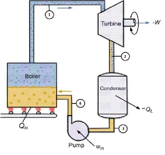
Above figure shows basic setup of steam turbine
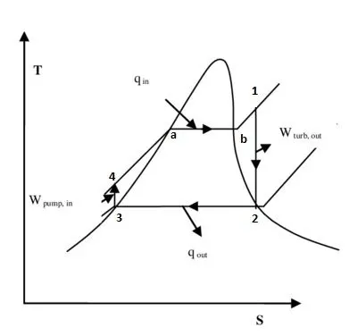
Above figure shows a standard T-S diagram with respect to the state.
Code & Explanation:
{*Note: The detailed explanation of code line by line is provided with in the code as comments}
Function code:
XSteam.m is a function code used to get data from standard steam table.
Maincode:
clear all
close all
clc

%display the topic
disp('RANKINE CYCLE')
%display each stages
fprintf('1-2  => isentropic Expansion in the turbine\n');
fprintf('2-3  => constant pressure heat removal in the condenser\n');
fprintf('3-4  => isentropic compression in the pump\n');
fprintf('4-1  => Constant pressure heat addition in the boiler\n');
fprintf('\n')

% enter the data data
% pressure at inlet of steam turbine (position 1)in bar
p1=input('\n value of pressure at turbine inlet,p1 (in bar) = ');
% Temperature at inlet of steam turbine(position 1) in celcius
t1=input('\n value of temperature at turbine inlet,t1 (in degree celceus) =');
% pressure at inlet of condenser(position 2) in bar
p2=input('\n value of pressure at condenser inlet,p2 (in bar) =');


% taking data from Xsteam file to solve values at position 1
%Enthalpy(h1) at t1,p1
h1=XSteam('h_pT',p1,t1);
%Entropy(s1) at t1,p1
s1=XSteam('s_pT',p1,t1);


% taking data from Xsteam file to solve values at position 2
%as the system is in closed loop and adiabatic entropy at inlet and outlet
%remains same (isentropic expansion)
s2=s1;
%Saturated liquid entropy at p2
sf2=XSteam('sL_p',p2);
%Saturated vapour entropy at p2
sg2=XSteam('sV_p',p2);
%Saturated liquid enthalpy at p2
hf2=XSteam('hL_p',p2);
%Saturated vapour enthalpy at p2
hg2=XSteam('hV_p',p2);
%vapour fraction at state 2
x2=(s2-sf2)/(sg2-sf2);
%Enthalpy at state 2
h2=hf2 +(x2*(hg2-hf2));


% taking data from Xsteam file to solve values at position 3
%from position 2 to posision 3 is isobaric heat regection.
%pressure remains constat as fluid goes out of condensor
p3=p2;
%as temprature is not known at t3 and also the after the vapour moves out
%of condenser it turns to liquid
%so we can consider saturated liquid entropyat pos.3 as s3
s3=XSteam('sL_p',p3);
%also we can consider saturated liquid enthalpy at pos.3 as h3
h3=XSteam('hL_p',p3);
%specific volume at p3
v3=XSteam('vL_p',p3);
%tempratute t3 at position 3
t3=XSteam('Tsat_p',p3);

%now we can write t2 and t3 are equal in ideal condition but in real life
%there is a deviation
t2=t3;


% taking data from Xsteam file to solve values at position 4
%as the fluid moves through the boiler pressure increases turns to super
%heated steam
%so entropy remains constat
s4=s3;
%also
p4=p1;
%Specific isochoric heat capacity as a function of pressure and entropy.
Cp4=XSteam('Cp_ps',p4,s4);
%specific isobaric heat capacity
Cv4=XSteam('Cv_ps',p4,s4);

k=Cp4/Cv4;
%temprature at sate 4
t4=t3/((p3/p4)^((k-1)/k));


%work done by turbine
W_T=h1-h2;

%work done by pump
W_P = v3*(p4-p3)*100;

%Enthalpy at state 4
h4 =h3-W_P;

%net work done for rankine cycle
W_net=W_T-W_P;

%heat addition to system
Q_in=h1-h4;

%heat rejection from system
Q_out=h2-h3;

%thermal efficiency if rankine cycle
T_eff=(W_net/Q_in)*100;

%mass flow rate of steam
SSC= (3600/W_net);


%to get values at position5 for proper graphical plot
%tempratute at state 5
t5=XSteam('Tsat_p',p1);
%to get entropy of s5
s5=XSteam('sL_p',p1);
%to get enthalpy h5
h5=XSteam('hL_p',p1);

%to get values at position6 for proper graphical plot
%to get entropy of s6
s6=XSteam('sV_p',p1);
%to get enthalpy h6
h6=XSteam('hV_p',p1);
%tempreture remains constat at 5 to 6
t6=t5;

%creating data set  for plotting saturation curve using XSteam
T_curve=linspace(1,400,1000);
for i=1:length(T_curve)
    s_l(i)=XSteam('sL_T',T_curve(i));
    s_v(i)=XSteam('sV_T',T_curve(i));
    h_l(i)=XSteam('hL_T',T_curve(i));
    h_v(i)=XSteam('hv_T',T_curve(i));
end


%plotting temprature vs entropy
figure(1);
hold on
%ploting saturation curve
plot(s_l,T_curve,'color','b');
plot(s_v,T_curve,'Color','b');

%state 1 to 2 isentropic expansion in turbine
plot([s1 s2], [t1 t2], 'LineWidth',1.25,'Color','r')
text(s1,t1,'1')

%state 2 to 3 constat heat rejection by condenser
plot([s2 s3], [t2 t3], 'LineWidth',1.25,'Color','r')
text(s2,t2-11,'2')

%state 3 to 4 isentropic compression in turbine
plot([s3 s4], [t3 t4], 'LineWidth',1.25,'Color','r')
text(s3,t3-11,'3')

%state 4 to 1 constant pressure heat addition
plot([s4 s5], [t4 t5], 'LineWidth',1.25,'Color','r')
text(s4,t4,'4')
plot([s5 s6], [t5 t6], 'LineWidth',1.25,'Color','r')
text(s5,t5+10,'a')
plot([s6 s1], [t6 t1], 'LineWidth',1.25,'Color','r')
text(s6,t6-10,'b')

%adding title label and legend
title('Temprature vs Entropy')
xlabel('Entropy (S) kj/kgk')
ylabel('Temperature (t) c')
legend('Saturation curve')


%plotting Entropy vs Enthalpy
figure(2)
hold on
%ploting saturation curve
plot(s_l,h_l,'color','b');
plot(s_v,h_v,'Color','b');

%state 1 to 2 isentropic expansion in turbine
plot([s1 s2], [h1 h2], 'LineWidth',1,'Color','g')
text(s1,h1,'1')

%state 2 to 3 constat heat rejection by condenser
plot([s2 s3], [h2 h3], 'LineWidth',1,'Color','g')
text(s2,h2,'2')

%state 3 to 4 isentropic compression in turbine
plot([s3 s4], [h3 h4], 'LineWidth',1,'Color','g')
text(s3,h3,'3')

%state 4 to 1 constant pressure heat addition
plot([s4 s1], [h4 h1], 'LineWidth',1,'Color','g')
text(s4,h4,'4')

%adding title label and legend
title('Entropy vs Enthalpy')
xlabel('Entropy (S) kj/kgk')
ylabel('enthalpy (h) kJ/kg')
legend('Saturation curve')


%display results0


disp('RESULTS')
fprintf('*note: p is pressure, t is temperature, h is enthalpy, s is entropy  \n');

fprintf('  At state 1 :\n');
fprintf('p1: %6.3f bar\n',p1);
fprintf('t1: %6.3f C\n',t1);
fprintf('h1: %6.3f KJ/kg\n',h1);
fprintf('s1: %6.3f  kj/kgk\n',s1);
fprintf(' \n');

fprintf('-----------------------------\n');
fprintf(' \n');
fprintf('  At state 2 :\n');
fprintf('p2: %6.3f bar\n',p2);
fprintf('t2: %6.3f C\n',t2);
fprintf('h2: %6.3f KJ/kg\n',h2);
fprintf('s2: %6.3f  kj/kgk\n',s2);
fprintf(' \n');

fprintf('-----------------------------\n');
fprintf(' \n');
fprintf('  At state 3 :\n');
fprintf('p3: %6.3f bar\n',p3);
fprintf('t3: %6.3f C\n',t3);
fprintf('h3: %6.3f KJ/kg\n',h3);
fprintf('s3: %6.3f  kj/kgk\n',s3);
fprintf(' \n');

fprintf('-----------------------------\n');
fprintf(' \n');
fprintf('  At state 4 :\n');
fprintf('p4: %6.3f bar\n',p4);
fprintf('t4: %6.3f C\n',t4);
fprintf('h4: %6.3f KJ/kg\n',h4);
fprintf('s4: %6.3f  kj/kgk\n',s4);
fprintf(' \n');
fprintf('-----------------------------\n');
fprintf(' \n');

fprintf('work done by tutbine W_T: %6.3f  kj/kg\n',W_T);
fprintf('work done by pump W_p: %6.3f C\n',W_P);
fprintf('total work done W_net: %6.3f KJ/kg\n',W_net);
fprintf('Efficiency T_eff: %6.3f  percent\n',T_eff);
fprintf('Mass flow rate/power SSC: %6.3f  KJ/KWh\n',SSC);
Initialy the the input value is entered pressure at state 1 p1, pressure at state 2 p2, tempreture at turbine input t1.
we calculate the enthalpy and entropy at state 1 from xsteam function
find the saturated liquid and vapour entropy and enthalpy from xsteam functionat state 2 at state 2 s1=s2.
find vapour fraction at state 2 using equation
`x_2=(s_2- s f_2)/(s g_2-s f_2)`
where,
sg2 is Saturated vapour entropy at p2
sf2 is Saturated liquid entropy at p2
Output:
result screen shots
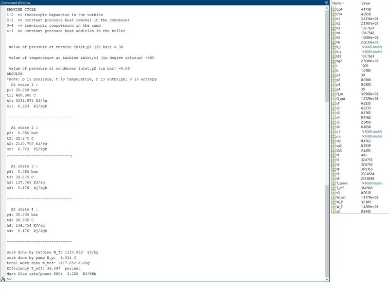
screenshot of graphs and result
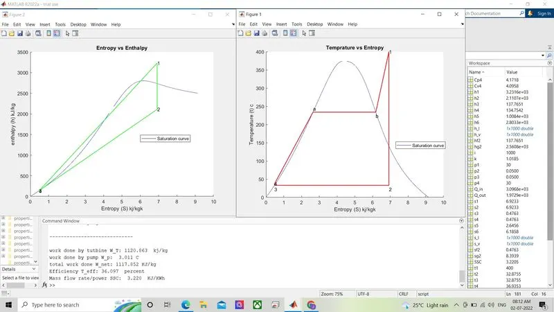
reference: