Project 2 - Rankine cycle Simulator
MATLAB PROJECT- RANKINE CYCLE 23 MAY 2022
SKILL LYNC- BHAVIN CHAUDHARY
The following submission includes program to simulate basic rankine cycle and also the rankine cycle with reheating.
1. CODE includes( Objective, Citation,Theory,Code)
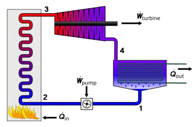
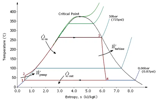
2. rankine cycle flow chart, Rankine cycle T-S Diagram and Thermal power plant P&ID Diagram(AUTOCAD PLANT 3D)
3. CASE 1 - T1=400'C, P1=30 bar, P2=0.05 bar OUTPUT, PLOT AND SCREENSHOT
4. CASE 2 - T1=400'C, P1=130 bar, P2=0.05 bar OUTPUT, PLOT AND SCREENSHOT
5. CASE 3 - T1=400'C, P1=210 bar, P2=0.05 bar OUTPUT, PLOT AND SCREENSHOT
6. CASE 4 - T1=800'C, P1=210 bar, P2=0.05 bar OUTPUT, PLOT AND SCREENSHOT
7. OBSERVATION
8. CONCLUSION
9. CITATION & REFERENCES
%WEEK 4 MATLAB BASIC- RANKINE CYCLE PROJECT
%SKILL-LYNC-BHAVIN CHAUDHARY-23 MAY 2022-RANKINE CYCLE PROJECT 2

%OBJECTIVE
%1.Create a basic rankine cycle simulation
%2.Code should calculate the state point of the rankine cycle(based on user input)
%3.Plot the corresponding T-S, H-S diagram
%4.Use standard Xsteam library to get data.
%5.calculate and plot the reheat rankine cycle
%6.Compare the Work output and efficiancy of Basic rankine and reheat cycle


%CITATION
%1.X Steam, Thermodynamic properties of water and steam- https://www.mathworks.com/matlabcentral/fileexchange/9817-x-steam-thermodynamic-properties-of-water-and-steam
%2.Book- Engineering Thermodynamics-Fourth Edition-Author PK Nag-Tata McGraw-Hill Publication-Chapter 12 Vapour power
%3.Book- Steam Table-Fouth Edition-Author C P Kothandaraman-New Age International Publishers
%4.Book- steam Table with Moillers Diagram- Author R S Khurmi-S Chand Publication
%5.Xsteam table -From skill-lync challenge google drive link
%6.Book-Power Plant Engineering-Third Edition-Author PK Nag-Tata McGraw-Hill Publication-Chapter 2-Analysis of Steam Cycle
%7.Book-Power Plant Engineering-Fourth Edition-Author-HG Katariya & JP Hadiya-Books India Publication- Chapter 2-High Pressure Boiler ,Chapter-4 Draught System, Chapter-5 Condenser & Cooling Tower
%8.Self Draw the P&ID of basic Thermal Power Plant -using AUTODESK Autocad Plant-3D Software
%9.WIKIPEDIA-Rankine cycle - https://en.wikipedia.org/wiki/Rankine_cycle

%%%%%%%%%%%%%%%%%%%%%%%%%%%%%%%%%%%%%%%%%%%%%%%%%%%%%%%%%%%%%%%%%%%%%%%%%%%%%%%%%%%%%%%%%%%%%%%%%%%%%%%%%%%%%%%%%%%%%%%%%%%%%%%%%%%%%%%%%%%

% UNDERSTAND THE RANKINE CYCLE- From book Engineering Thermodynamics by PK Nag
% Chapter 12 Vapour power cycles
% CALCULATION OF PARAMETERS OF EACH PROCESS STATE
% BAasic Rankine Cycle Assumptions
   % 1. The process is a steady flow operating cycle with controled volume. Hence, we will apply steady flow energy equation SFEE
   % 2. The mass of fluid is considered unit
   % 3. The changes in Kinetic energy and potential energy are neglected
   % 4. The work and heat quantities are calculated in terms of fluid properties & not of the actual system ( mechanical output)
   % 5. The rankine cycle is completely isolated and no there is no heat loss through the turbine, pump, and the piping system
% Initial Paramters of Rankine Cycle
   % 1. Pressure range of system i.e highest & lowest steam pressure
   % 2. Temperature range of system i.e highest and lowest temperature
   % 3. Turbine steam parameter i.e wet, dry saturated or superheated
   % 4. Heat Input in boiler to achieve steam property at turbine inlet
   % 5. Heat release or cooling required to achive condensate property at pump inlet
% Component of simple rankine cycle system
% 1. TURBINE-
   % 1.1 process observed is reversible adiabatic steam expansion, pressure decreases
   % 1.2 Input state 1 of steam can be wet, dry saturated or superheated. Generally, superheated steam enters turbine
   % 1.3 Exit state 2 of steam is either wet or dry saturated.
   % 1.4 The result of process is turbine work or work by the system.
   % The SFEE for Turbine
   % Wt=h1-h2
% 2. CONDENSOR-
   % 2.1 process observed is reversible isobaric heat rejection (steam condensation)
   % 2.2 Input state 2 of steam is wet or dry saturated
   % 2.3 Output state 3 is saturated liquid water or 100% wet steam/0% dry steam
   % 2.4 The result of process is latent heat tranfer from the system to surroundings
   % The SFEE for Condensor
   % Q2=h2-h3
% 3. PUMP-
   % 3.1 process observed is reversible adiabatic compression, pressure increases
   % 3.2 Input state 3 of working meduium is condensate or water.
   % 3.3 exits state 4 is pressurised water.
   % 3.4 The result of the process is pump work or work on the system.
   % The SFEE for pump
   % Wp=h4-h3
% 4. BOILER-
   % 4.1 process observed is isobaric heat addition (steam formation)
   % 4.2 Input state 4 of fluid is pressurised water.
   % 4.3 Exit state 1 of fluid is superheated steam.
   % 4.4 The result of proess is heat addition = sensible heat of water + latent heat of boiling + sensible heat to form suprheated steam
   % The SFFE for boiler
   % Q1=h1-h4

% The properties of steam and its state are consisdered for the process.
% This data or the steam property data is derived from steam table or Xsteam directory.
% Hence, rankine cycle includes boiler, using heat from combustion or any source to convert the state of liquid water into vapour state.
% This vapour state of water with high temperature and pressure is used to derive work or mechanical energy
% Later, condensation sysytem is used to convvert the vapour into liquid state.
% Finally, the liquid water is pumped into boiler to complete the thermodynamic cycle.

% Hence, external combustion energy is converted into mechanical energy using rankine cycle.

%%%%%%%%%%%%%%%%%%%%%%%%%%%%%%%%%%%%%%%%%%%%%%%%%%%%%%%%%%%%%%%%%%%%%%%%%%%%%%%%%%%%%%%%%%%%%%%%%%%%%%%%%%%%%%%%%%%%%%%%%%%%%%%%

% X STEAM INTRODUCTION
%X Steam for matlab is a implementation of the IAPWS IF97 standard formulation.
%It provides accurate thermo hydraulic data for water and steam and mixtures of water and steam in the region:
%0°C < temperature < 2000°C for 0.00611 bar a < pressure < 100 bar a
%0°C < temperature < 1000°C for 0.00611 bar a < pressure < 1000 bar a

%USING THE MATLAB IMPLEMENTATION
%X Steam are available both for matlab and for MS excel. The MS Excel version can be useful also for matlab users to get valid calling functions.
%The XSteam code are used in the following way:
%Out=XSteam(‘function name’,In1,In2)
%Function name are the name on the XSteam function and In1 and In2 are the inputs to that function. The results are returned (in this case to Out).
%Example: XSteam(‘rho_pT’,1,200) returns the density at 1 bar and 200°C.

%The notaions used in XSteam are as below
% Notation / Quantity                       / Unit
%   T      /Temperature                     / °C
%   p      /Pressure                        / bar
%   h      /Enthalpy                        / kJ/kg
%   v      /Specific                        / volume m3/kg
%   rho    /Density                         / kg/ m3
%   s      /Specific entropy                / kJ/(kg °C)
%   u      /Specific internal energy        / kJ/kg
%   Cp     /Specific isobaric heat capacity / kJ/(kg °C)
%   Cv     /Specific isochoric heat capacity/ kJ/(kg °C)
%   w      /Speed of sound                  / m/s
%   mu     /Viscosity                       / Pa s
%   tc     /Thermal Conductivity            / W/(m °C)
%   st     /Surface Tension                 / N/m
%   x      /Vapour fraction (0-1)           / -
%   vx     /Vapour Volume Fraction (0-1)    / -


%XSTEAM CALLING FUNCTIONS
%3.1 Temperature
% Function / In1 / In2 / Out
% Tsat_p   / p   / -   / Saturation temperature
% T_ph     / p   / H   / Temperture as a function of pressure and enthalpy
% T_ps     / p   / S   / Temperture as a function of pressure and entropy
% T_hs     / h   / S   / Temperture as a function of enthalpy and entropy

%3.2 Pressure
% Function / In1 / In2 / Out
% psat_T   / T   /     / Saturation pressure
% p_hs     / h   / s   / Pressure as a function of h and s.
% p_hrho   / h   / rho / Pressure as a function of h and rho (density).Very unaccurate for solid water region since it's almost incompressible!

%3.3 Enthalpy
% Function / In1 / In2 / Out
% hV_p     / p   /     / Saturated vapour enthalpy
% hL_p     / p   /     / Saturated liquid enthalpy
% hV_T     / T   /     / Saturated vapour enthalpy
% hL_T     / T   /     / Saturated liquid enthalpy
% h_pT     / p   / T   / Entalpy as a function of pressure and temperature.
% h_ps     / p   / s   / Entalpy as a function of pressure and entropy.
% h_px     / p   / x   / Entalpy as a function of pressure and vapour fraction
% h_Tx     / T   / X   / Entalpy as a function of temperature and vapour fraction
% h_prho   / p   / rho / Entalpy as a function of pressure and density. Observe for low temperatures (liquid) this equation has 2 solutions.(Not valid!!)

%3.4 Specific volume
% Function / In1 / In2 / Out
% vV_p     / p   /     / Saturated vapour volume
% vL_p     / p   /     / Saturated liquid volume
% vV_T     / T   /     / Saturated vapour volume
% vL_T     / T   /     / Saturated liquid volume
% v_pT     / p   / T   / Specific volume as a function of pressure and temperature.
% v_ph     / p   / h   / Specific volume as a function of pressure and enthalpy
% v_ps     / p   / s   / Specific volume as a function of pressure and entropy.

%3.5 Density
% Function / In1 / In2 / Out
% rhoV_p   / p   /     / Saturated vapour density
% rhoL_p   / p   /     / Saturated liquid density
% rhoV_T   / T   /     / Saturated vapour density
% rhoL_T   / T   /     / Saturated liquid density
% rho_pT   / p   / T   / Density as a function of pressure and temperature.
% rho_ph   / p   / h   / Density as a function of pressure and enthalpy
% rho_ps   / p   / s   / Density as a function of pressure and entropy.

%3.6 Specific entropy
% Function / In1 / In2 / Out
% sV_p     / p   /     / Saturated vapour entropy
% sL_p     / p   /     / Saturated liquid entropy
% sV_T     / T   /     / Saturated vapour entropy
% sL_T     / T   /     / Saturated liquid entropy
% s_pT     / p   / T   / Specific entropy as a function of pressure and temperature (Returns saturated vapour entalpy if mixture.)
% s_ph     / p   / h   / Specific entropy as a function of pressure and enthalpy

%3.7 Specific internal energy
% Function / In1 / In2 / Out
% uV_p     / p   /     / Saturated vapour internal energy
% uL_p     / p   /     / Saturated liquid internal energy
% uV_T     / T   /     / Saturated vapour internal energy
% uL_T     / T   /     / Saturated liquid internal energy
% u_pT     / p   / T   / Specific internal energy as a function of pressure and temperature.
% u_ph     / p   / h   / Specific internal energy as a function of pressure and enthalpy
% u_ps     / p   / s   / Specific internal energy as a function of pressure and entropy.

%3.8 Specific isobaric heat capacity
% Function / In1 / In2 / Out
% CpV_p    / p   /     / Saturated vapour heat capacity
% CpL_p    / p   /     / Saturated liquid heat capacity
% CpV_T    / T   /     / Saturated vapour heat capacity
% CpL_T    / T   /     / Saturated liquid heat capacity
% Cp_pT    / p   / T   / Specific isobaric heat capacity as a function of pressure and temperature.
% Cp_ph    / p   / h   / Specific isobaric heat capacity as a function of pressure and enthalpy
% Cp_ps    / p   / s   / Specific isobaric heat capacity as a function of pressure and entropy.

%3.9 Specific isochoric heat capacity
% Function / In1 / In2 / Out
% CvV_p    / p   /     / Saturated vapour isochoric heat capacity
% CvL_p    / p   /     / Saturated liquid isochoric heat capacity
% CvV_T    / T   /     / Saturated vapour isochoric heat capacity
% CvL_T    / T   /     / Saturated liquid isochoric heat capacity
% Cv_pT    / p   / T   / Specific isochoric heat capacity as a function of pressure and temperature.
% Cv_ph    / p   / h   / Specific isochoric heat capacity as a function of pressure and enthalpy
% Cv_ps    / p   / s   / Specific isochoric heat capacity as a function of pressure and entropy.

%3.10 Speed of sound
% Function / In1 / In2 / Out
% wV_p     / p   /     / Saturated vapour speed of sound
% wL_p     / p   /     / Saturated liquid speed of sound
% wV_T     / T   /     / Saturated vapour speed of sound
% wL_T     / T   /     / Saturated liquid speed of sound
% w_pT     / p   / T   / Speed of sound as a function of pressure and temperature.
% w_ph     / p   / h   / Speed of sound as a function of pressure and enthalpy
% w_ps     / p   / s   / Speed of sound as a function of pressure and entropy.

%3.11 Viscosity
% Viscosity is not part of IAPWS Steam IF97. Equations from "Revised Release on the IAPWS Formulation 1985 for the Viscosity of Ordinary Water Substance", 2003 are used.
% Viscosity in the mixed region (4) is interpolated according to the density. This is not true since it will be two fases.
% Function / In1 / In2 / Out
% my_pT    / p   / T   / Viscosity as a function of pressure and temperature.
% my_ph    / p   / h   / Viscosity as a function of pressure and enthalpy
% my_ps    / p   / s   / Viscosity as a function of pressure and entropy.

%3.12 Thermal Conductivity
% Revised release on the IAPS Formulation 1985 for the Thermal Conductivity of ordinary water substance (IAPWS 1998)
% Function / In1 / In2 / Out
% tcL_p    / p   /     / Saturated vapour thermal conductivity
% tcV_p    / p   /     / Saturated liquid thermal conductivity
% tcL_T    / T   /     / Saturated vapour thermal conductivity
% tcV_T    / T   /     / Saturated liquid thermal conductivity
% tc_pT    / p   / T   / Thermal conductivity as a function of pressure and temperature.
% tc_ph    / p   / h   / Thermal conductivity as a function of pressure and enthalpy
% tc_hs    / h   / s   / Thermal conductivity as a function of enthalpy and entropy

%3.13 Surface Tension
% IAPWS Release on Surface Tension of Ordinary Water Substance, September 1994
% Function / In1 / In2 / Out
% st_T     / T   /     / Surface tension for two phase water/steam as a function of T
% st_p     / p   /     / Surface tension for two phase water/steam as a function of T

%3.14 Vapour fraction
% Function / In1 / In2 / Out
% x_ph     / p   / h   / Surface tension for two phase water/steam as a function of T
% x_ps     / p   / s   / Surface tension for two phase water/steam as a function of T

%3.15 Vapour Volume Fraction
% Observe that vapour volume fraction is very sensitive.
% Vapour volume is about 1000 times greater than liquid volume and therefore vapour volume fraction gets close to the accurancy of IAPWS IF-97
% Function / In1 / In2 / Out
% vx_ph    / p   / h   / Vapour volume fraction as a function of pressure and enthalpy
% vx_ps    / p   / s   / Vapour volume fraction as a function of pressure and entropy.

%%%%%%%%%%%%%%%%%%%%%%%%%%%%%%%%%%%%%%%%%%%%%%%%%%%%%%%%%%%%%%%%%%%%%%%%%%%%%%%%%%%%%%%%%%%%%%%%%%%%%%%%%%%%%%%%%%%%%%%%%%%%%%%%%%%%%%%%


% CODING OF BASIC RANKINE CYCLE & BASIC RANKINE CYCLE WITH REHEATING

clear all
close all
clc

%State point 1 Boiler outlet or turbine inlet
syms T1   % Variable temperature in degree celcius
syms P1   % Variable Pressure in bar
syms H1   % Variable Enthalpy in KJ/Kg
syms S1   % Variable Entropy in KJ/Kg-C
%State point 1s Reheat low- primary turbine outlet
syms T1s  % Variable temperature in degree celcius
syms P1s  % Variable Pressure in bar
syms H1s  % Variable Enthalpy in KJ/Kg
syms S1s  % Variable Entropy in KJ/Kg-C
%State point 2h reheat high- secondary turbine inlet
syms T2h  % Variable temperature in degree celcius
syms P2h  % Variable Pressure in bar
syms H2h  % Variable Enthalpy in KJ/Kg
syms S2h  % Variable Entropy in KJ/Kg-C
%State point 2l reheat low-secondary turbine outlet
syms T2l  % Variable temperature in degree celcius
syms P2l  % Variable Pressure in bar
syms H2l  % Variable Enthalpy in KJ/Kg
syms S2l  % Variable Entropy in KJ/Kg-C
%State point 2 Turbine outlet or condenser inlet
syms T2   % Variable temperature in degree celcius
syms P2   % Variable Pressure in bar
syms H2   % Variable Enthalpy in KJ/Kg
syms S2   % Variable Entropy in KJ/Kg-C
%State point 3 Condenser outlet or Pump inlet
syms T3   % Variable temperature in degree celcius
syms P3   % Variable Pressure in bar
syms H3   % Variable Enthalpy in KJ/Kg
syms S3   % Variable Entropy in KJ/Kg-C
%State point 4 Pump outlet or boiler inlet
syms T4   % Variable temperature in degree celcius
syms P4   % Variable Pressure in bar
syms H4   % Variable Enthalpy in KJ/Kg
syms S4   % Variable Entropy in KJ/Kg-C

%Assumption in calculation
%1. The heat addition, heat rejection, pump work and turbine work are function of enthalpy of steam and water.
%2. The system of piping and other accessories are 100% insulated and there is no heat loss in between
%3. The process are assumed to be linear function of property. Curve fitting of steam data is not taken in consideration.

disp('RANKINE CYCLE CALCULATION FOR THERMAL POWER PLANT STEAM BASED')
PERFORM=input('Enter 1 if you want to calculate rankine cycle work, else enter 0=')

while PERFORM==1
disp('BASIC RANKINE CYCLE STATE POINTS %%%%%%%%%%%%%%%%%%%%%%%%%%%%%%%%%%%%%%%%%%%%%%%%%%%%%%%%')
%Calculation of Rankine cycle State point 1-High pressure High tempearature superheated steam at turbine inlet
T1=input('enter the value of steam temperature at turbine inlet STATE POINT 1=')
P1=input('enter the value of steam pressure at turbine inlet STATE POINT 1=')
disp('Enthalpy of steam at turbine inlet STATE POINT 1')
H1=XSteam('h_pT',P1,T1)
disp('Entropy of steam at turbine inlet STATE POINT 1')
S1=XSteam('s_pT',P1,T1)

%Calculation of Rankine cycle state 2-Turbine Outlet or Condenser inlet
P2=input('enter the value of steam pressure STATE POINT 2 - turbine outlet or condenser inlet=')
disp('The entropy of steam STATE POINT 2 - condenser inlet')
S2=S1
disp('The temperature of steam STATE POINT 2 - Turbine oullet or condenser inlet')
T2=XSteam('T_ps',P2,S2)
disp('The Enthalpy of steam STATE POINT 2- turbine outlet or condenser inlet')
H2=XSteam('h_ps',P2,S2)

%Calculation of rankine cycle state 3 Condenser outlet or Pump inlet
disp('The Pressure of condensate STATE POINT 3- the condenser outlet or pump inlet')
P3=P2
disp('The Temperature of condensate STATE POINT 3 - the condenser outlet or pump inlet')
T3=T2
disp('The Entropy of condensate STATE POINT 3 - the condenser outlet or pump inlet')
S3=XSteam('sL_T',T3)
disp('The Enthalpy of condensate STATE POINT 3 - the condenser outlet or pump inlet')
H3=XSteam('hL_T',T3)

%Calculation of rankine cycle state 4 high pressure low temperature liquid water at Pump outlet and boiler inlet
disp('The Entropy of liquid water STATE POINT 4 - at pump outlet')
S4=S3
disp('The Pressure of liquid water STATE POINT 4 - at pump outlet')
P4=P1
disp('The Enthalpy of liquid water STATE POINT 4 - at pump outlet')
H4=XSteam('h_ps',P4,S4)
disp('The Tempearature of liquid water STATE POINT 4 - at pump outlet')
T4=XSteam('T_ps',P4,S4)

%Calculation of rankine cycle state A-Pressurised Saturated liquid after primary heating in boiler
disp('The Pressure of saturated liquid  STATE POINT A - after primary heating in boiler')
Pa=P4
disp('The Entropy of saturated liquid  STATE POINT A - after primary heating in boiler')
Sa=XSteam('sL_p',Pa)
disp('The Enthalpy of saturated liquid  STATE POINT A - after primary heating in boiler')
Ha=XSteam('hL_P',Pa)
disp('The Temperature of saturated liquid  STATE POINT A - after primary heating in boiler')
Ta=XSteam('T_ps',Pa,Sa)

%Calculation of Rankine cycle state B-Pressurised Saturated Vapour after heating in Evaporator in boiler
disp('The Pressure of saturated Vapour STATE POINT B - after heating in boiler Evaporator')
Pb=Pa
disp('The Temperature of saturated Vapour STATE POINT B - after heating in boiler Evaporator')
Tb=Ta
disp('The Entropy of saturated Vapour STATE POINT B - after heating in boiler Evaporator')
Sb=XSteam('sV_p',Pb)
disp('The Enthaply of saturated Vapour STATE POINT B - after heating in boiler Evaporator')
Hb=XSteam('hV_P',Pb)

%Calculation of output and efficiency of the Rankine Cycle
disp('CALCULATION OF BASIC RANKINE CYCLE')
disp('Heat Addition in basic rankine cycle boiler in KJ/kg')
Qadd=H1-H4
disp('Heat Rejected in basic rankine cycle condenser in KJ/kg')
Qrej=H2-H3
disp('Turbine Work of basic rankine cycle in KJ/kg')
Wt=H1-H2
disp('Pump work input for basic rankine cycle in KJ/kg')
Wp=H4-H3
disp('Net work of basic rankine cycle in KJ/kg')
Wnet=Wt-Wp
disp('Back work ratio for basic rankine cycle')
Wr=Wp/Wt
disp('Thermal efficiency of rankine cycle system')
Efficiency_thermal=Wnet/Qadd

%1. Basic Rankine cycle T-S Phase curve plot
% this is the data from book of steam table- refer citation.
% Note, the saturated steam data is upto 374.15 degree celcius temperature and 221.5 bar pressure only
t=linspace(0,375,3751);

% this for loop plots all the saturated water and saturated steam state points
 for i=1:length(t)
    T=t(i);
    Sl=XSteam('sL_T',T);
    Sv=XSteam('sV_T',T);
    hold on
    subplot(2,2,1)     % this command generates plot window 2x2 matrix & will plot in row=1 column=1
    plot(Sl,T,'.','color','k','Markersize',0.25)
    plot(Sv,T,'.','color','k','Markersize',0.25)
 end
% The following code plots the state points and corresponding connecting process path
    plot(S1,T1,'O','color','r','Markersize',5) % this command Plots the state point 1 turbine inlet
    plot(S2,T2,'O','color','b','Markersize',5) % this command Plots the state point 2 condenser inlet
    plot(S3,T3,'O','color','k','Markersize',5) % this command Plots the state point 3 pump inlet
    plot(S4,T4,'O','color','k','Markersize',5) % this command Plots the state point 4 boiler inlet primary heating
    plot(Sa,Ta,'O','color','g','Markersize',5) % this command Plots the state point A evaporator inlet
    plot(Sb,Tb,'O','color','g','Markersize',5) % this command Plots the state point B boiler superheater inlet
    line([S1 S2],[T1 T2],'color','r')           % this command plots the process path from state 1 to state 2
    line([S2 S3],[T2 T3],'color','b')           % this command plots the process path from state 2 to state 3
    line([S3 S4],[T3 T4],'color','k')           % this command plots the process path from state 3 to state 4
    line([S4 Sa],[T4 Ta],'color','b')           % this command plots the process path from state 4 to state A
    line([Sa Sb],[Ta Tb],'color','g')           % this command plots the process path from state A to state B
    line([Sb S1],[Tb T1],'color','r')           % this command plots the process path from state B to state 1
    title('Rankine Cycle T-S plot')             % this command adds title to elemented plot window
    xlabel('Entropy(KJ/Kg.deg-C)')
    ylabel('Temperature(deg-C)')

%2. Basic Rankine cycle H-S Phase curve plot
% this is the data from book of steam table- refer citation.
% Note, the saturated steam data is upto 374.15 degree celcius temperature and supercritical 221.2 bar pressure only
t=linspace(0,375,3751);

 for i=1:length(t)
    T=t(i);
    Sl=XSteam('sL_T',T);
    Sv=XSteam('sV_T',T);
    Hl=XSteam('hL_T',T);
    Hv=XSteam('hV_T',T);
    hold on
    subplot(2,2,2)      % this command generates plot window 2x2 matrix & will plot in row=1 column=2

    plot(Sl,Hl,'.','color','k','Markersize',0.25)
    plot(Sv,Hv,'.','color','k','Markersize',0.25)
 end
    plot(S1,H1,'O','color','r','Markersize',5) % this command Plots the state point 1 turbine inlet
    plot(S2,H2,'O','color','b','Markersize',5) % this command Plots the state point 2 condenser inlet
    plot(S3,H3,'O','color','k','Markersize',5) % this command Plots the state point 3 pump inlet
    plot(S4,H4,'O','color','k','Markersize',5) % this command Plots the state point 4 boiler primary heater inlet
    plot(Sa,Ha,'O','color','g','Markersize',5) % this command Plots the state point A boiler evaporator inlet
    plot(Sb,Hb,'O','color','g','Markersize',5) % this command Plots the state point B boiler superheater inlet
    line([S1 S2],[H1 H2],'color','r')           % this command plots the process path from state 1 to state 2
    line([S2 S3],[H2 H3],'color','b')           % this command plots the process path from state 2 to state 3
    line([S3 S4],[H3 H4],'color','k')           % this command plots the process path from state 3 to state 4
    line([S4 Sa],[H4 Ha],'color','b')           % this command plots the process path from state 4 to state A
    line([Sa Sb],[Ha Hb],'color','g')           % this command plots the process path from state A to state B
    line([Sb S1],[Hb H1],'color','r')           % this command plots the process path from state B to state 1
    title('Rankine Cycle H-S plot')             % this command adds title to elemented plot window
    xlabel('Entropy(KJ/Kg.deg-C)')
    ylabel('Enthalpy(KJ/Kg)')


%Calculation of Rankine Cycle with Reheat system and secondary turbine
disp('BASIC RANKINE CYCLE WITH REHEAT STATE POINTS  %%%%%%%%%%%%%%%%%%%%%%%%%%%%%%%%%%%%%%%%%%%%%%%%%%%%%%%%%%')
%Calculation of Reheat STATE Point 1s - Saturated vapour at the outlet of primary turbine and inlet of reheat system
disp('The pressure at primary turbine outlet')
if (0<=P1)&&(P1<50)
    fraction=0.205
else
    if (50<=P1)&&(P1<100)
        fraction=0.215
    else
        if (100<=P1)&&(P1<150)
            fraction=0.225
        else
            if (150<=P1)&&(P1<200)
               fraction=0.235
            else
                if (200<=P1)&&(P1<220)
                    fraction=0.245
                else
                    disp('Pressure range is beyond calculation')
                end
            end
        end
    end
end

disp('The Pressure of saturated steam STATE POINT 1s - at the outlet of primary turbine or reheater inlet')
P1s=fraction*P1
disp('The Entropy of saturated steam STATE POINT 1s - at the outlet of primary turbine or reheater inlet')
S1s=S1
disp('The Temperature of saturated steam STATE POINT 1s - at the outlet of primary turbine or reheater inlet')
T1s=XSteam('T_ps',P1s,S1s)
disp('The Enthalpy of saturated steam STATE POINT 1s - at the outlet of primary turbine or reheater inlet')
H1s=XSteam('h_ps',P1s,S1s)

%Calculation of reheat STATE Point 2h - Superheated steam at secondary turbine inlet or reheat outlet
disp('The Temperature of superheatd steam STATE POINT 2h - at secondary turbine inlet')
T2h=T1
disp('The Pressure of superheatd steam STATE POINT 2h - at secondary turbine inlet')
P2h=P1s
disp('The Enthalpy of superheatd steam STATE POINT 2h - at secondary turbine inlet')
H2h=XSteam('h_pT',P2h,T2h)
disp('The Entropy of superheatd steam STATE POINT 2h - at secondary turbine inlet')
S2h=XSteam('s_pT',P2h,T2h)

%Calculation of reheat STATE Point 2l - Steam outlet from secondary turbine or expanded condenser inlet
disp('The Temperature of exhaust steam STATE POINT 2l - at the condenser inlet')
P2l=P2
disp('The Entropy of exhaust steam STATE POINT 2l - at the condenser inlet')
S2l=S2h
disp('The Temperature of exhaust steam STATE POINT 2l - at the condenser inlet')
T2l=XSteam('T_ps',P2l,S2l)
disp('The Enthalpy of exhaust steam STATE POINT 2l - at the condenser inlet')
H2l=XSteam('h_ps',P2l,S2l)

%Calculation of output of Rankine cycle with reheat system
disp('CALCULATION OF RANKINE CYCLE WITH REHEAT SYSTEM')
disp('Heat addition in boile in KJ/kgr')
Qadd_boiler=H1-H4
disp('Heat addition in reheat system in KJ/kg')
Qadd_reheat=H2h-H1s
disp('Net heat addition in system in KJ/kg')
Qadd_net=Qadd_boiler+Qadd_reheat
disp('Heat rejected in expanded condenser in KJ/kg')
Qrej_net=H2l-H3
disp('Work output in primary turbine in KJ/kg')
Wt_primary=H1-H1s
disp('Work output in secondary turbine')
Wt_secondary=H2h-H2l
disp('Net turbine work in KJ/kg')
Wt_net=Wt_primary+Wt_secondary
disp('Net pumping work in KJ/kg')
Wp_reheat=H4-H3
disp('Net work output of system in KJ/kg')
Wnet_reheat=Wt_net-Wp
disp('Back work ratio')
Wr_reheat=Wp/Wt_net
disp('Thermal efficiency of rankine cycle with reheat system')
Efficiency_thermal_reheat=Wnet_reheat/Qadd_net

%3.Ranine cycle with reheat system T-S Phase curve plot
% this is the data from book of steam table- refer citation.
% Note, the saturated steam data is upto 374.15 degree celcius temperature and supercritical 221.2 bar pressure only
t=linspace(0,375,3751);
 for i=1:length(t)
    T=t(i);
    Sl=XSteam('sL_T',T);
    Sv=XSteam('sV_T',T);
    hold on
    subplot(2,2,3)      % this command generates plot window 2x2 matrix & will plot in row=2 column=1
    plot(Sl,T,'.','color','k','Markersize',0.25)
    plot(Sv,T,'.','color','k','Markersize',0.25)
 end
    plot(S1,T1,'O','color','r','Markersize',5)     % this command Plots the state point 1  primary turbine inlet
    plot(S1s,T1s,'O','color','r','Markersize',5)   % this command Plots the state point 1s Primay turbine outlet or reheat system inlet
    plot(S2h,T2h,'O','color','r','Markersize',5)   % this command Plots the state point 2h secondary turbine inlet or reheat system outlet
    plot(S2l,T2l,'O','color','b','Markersize',5)   % this command Plots the state point 2l secondary turbine outlet
    plot(S2,T2,'O','color','b','Markersize',5)     % this command Plots the state point 2  expanded condenser inlet
    plot(S3,T3,'O','color','k','Markersize',5)     % this command Plots the state point 3  pump inlet
    plot(S4,T4,'O','color','k','Markersize',5)     % this command Plots the state point 4  pump outlet or boiler primary heating inlet
    plot(Sa,Ta,'O','color','g','Markersize',5)     % this command Plots the state point A  boiler evaporator inlet
    plot(Sb,Tb,'O','color','g','Markersize',5)     % this command Plots the state point B  boiler superheater inlet
    line([S1 S1s],[T1 T1s],'color','r')             % this command plots the process path from state 1 to state 1s
    line([S1s S2h],[T1s T2h],'color','r')           % this command plots the process path from state 1s to state 2h
    line([S2h S2l],[T2h T2l],'color','r')           % this command plots the process path from state 2h to state 2l
    line([S2l S2],[T2l T2],'color','c')             % this command plots the process path from state 2l to state 2
    line([S2 S3],[T2 T3],'color','b')               % this command plots the process path from state 2 to state 3
    line([S3 S4],[T3 T4],'color','k')               % this command plots the process path from state 3 to state 4
    line([S4 Sa],[T4 Ta],'color','b')               % this command plots the process path from state 4 to state A
    line([Sa Sb],[Ta Tb],'color','g')               % this command plots the process path from state A to state B
    line([Sb S1],[Tb T1],'color','r')               % this command plots the process path from state B to state 1
    title('Rankine Reheat Cycle T-S plot')
    xlabel('Entropy(KJ/Kg.deg-C)')
    ylabel('Temperature(deg-C)')

%4. H-S Phase curve plot
% this is the data from book of steam table- refer citation.
% Note, the saturated steam data is upto 374.15 degree celcius temperature and supercritical 221.2 bar pressure only
t=linspace(0,375,3751);
 for i=1:length(t)
    T=t(i);
    Sl=XSteam('sL_T',T);
    Sv=XSteam('sV_T',T);
    Hl=XSteam('hL_T',T);
    Hv=XSteam('hV_T',T);
    hold on
    subplot(2,2,4)      % this command generates plot window 2x2 matrix & will plot in row=2 column=2
    plot(Sl,Hl,'.','color','k','Markersize',0.25)
    plot(Sv,Hv,'.','color','k','Markersize',0.25)
 end
    plot(S1,H1,'O','color','r','Markersize',5)     % this command Plots the state point 1  primary turbine inlet
    plot(S1s,H1s,'O','color','r','Markersize',5)   % this command Plots the state point 1s Primay turbine outlet or reheat system inlet
    plot(S2h,H2h,'O','color','r','Markersize',5)   % this command Plots the state point 2h secondary turbine inlet or reheat system outlet
    plot(S2l,H2l,'O','color','b','Markersize',5)   % this command Plots the state point 2l secondary turbine outlet
    plot(S2,H2,'O','color','b','Markersize',5)     % this command Plots the state point 2  expanded condenser inlet
    plot(S3,H3,'O','color','k','Markersize',5)     % this command Plots the state point 3  pump inlet
    plot(S4,H4,'O','color','k','Markersize',5)     % this command Plots the state point 4  pump outlet or boiler primary heating inlet
    plot(Sa,Ha,'O','color','g','Markersize',5)     % this command Plots the state point A  boiler evaporator inlet
    plot(Sb,Hb,'O','color','g','Markersize',5)     % this command Plots the state point B  boiler superheater inlet
    line([S1 S1s],[H1 H1s],'color','r')             % this command plots the process path from state 1 to state 1s
    line([S1s S2h],[H1s H2h],'color','r')           % this command plots the process path from state 1s to state 2h
    line([S2h S2l],[H2h H2l],'color','r')           % this command plots the process path from state 2h to state 2l
    line([S2l S2],[H2l H2],'color','c')             % this command plots the process path from state 2l to state 2
    line([S2 S3],[H2 H3],'color','b')               % this command plots the process path from state 2 to state 3
    line([S3 S4],[H3 H4],'color','k')               % this command plots the process path from state 3 to state 4
    line([S4 Sa],[H4 Ha],'color','k')               % this command plots the process path from state 4 to state A
    line([Sa Sb],[Ha Hb],'color','g')               % this command plots the process path from state A to state B
    line([Sb S1],[Hb H1],'color','r')               % this command plots the process path from state B to state 1
    title('Rankine Reheat Cycle H-S plot')
    xlabel('Entropy(KJ/Kg.deg-C)')
    ylabel('Enthalpy(KJ/Kg)')

PERFORM=input('do yo want to continue the calculation of Rankine cycle? if yes enter 1 if No enter 0 =');
if PERFORM==0
    disp('you have exited from the program')
    break
end
end
2.
BASIC RANKINE CYCLE FLOW CHART from link https://en.wikipedia.org/wiki/Rankine_cycle
BASIC RANKINE CYCLE T-S PLOT from link https://en.wikipedia.org/wiki/Rankine_cycle
BASIC RANKINE CYCLE PIPING AND INSTRUMENTATION DIAGRAM AUTOCAD DRAWING (PHOTO JPG FORMAT)
SELF PREPARED USING AUTOCAD PLANT 3D SOFTWARE.
3. CASE 1 T=400'C, P1=30bar, P2=0.05bar
1.1 CODE OUTPUT
RANKINE CYCLE CALCULATION FOR THERMAL POWER PLANT STEAM BASED
Enter 1 if you want to calculate rankine cycle work, else enter 0=1
PERFORM =
1
BASIC RANKINE CYCLE STATE POINTS %%%%%%%%%%%%%%%%%%%%%%%%%%%%%%%%%%%%%%%%%%%%%%%%%%%%%%%%
enter the value of steam temperature at turbine inlet STATE POINT 1=400
T1 =
400
enter the value of steam pressure at turbine inlet STATE POINT 1=30
P1 =
30
Enthalpy of steam at turbine inlet STATE POINT 1
H1 =
3.2316e+03
Entropy of steam at turbine inlet STATE POINT 1
S1 =
6.9233
enter the value of steam pressure STATE POINT 2 - turbine outlet or condenser inlet=0.05
P2 =
0.0500
The entropy of steam STATE POINT 2 - condenser inlet
S2 =
6.9233
The temperature of steam STATE POINT 2 - Turbine oullet or condenser inlet
T2 =
32.8755
The Enthalpy of steam STATE POINT 2- turbine outlet or condenser inlet
H2 =
2.1107e+03
The Pressure of condensate STATE POINT 3- the condenser outlet or pump inlet
P3 =
0.0500
The Temperature of condensate STATE POINT 3 - the condenser outlet or pump inlet
T3 =
32.8755
The Entropy of condensate STATE POINT 3 - the condenser outlet or pump inlet
S3 =
0.4763
The Enthalpy of condensate STATE POINT 3 - the condenser outlet or pump inlet
H3 =
137.7651
The Entropy of liquid water STATE POINT 4 - at pump outlet
S4 =
0.4763
The Pressure of liquid water STATE POINT 4 - at pump outlet
P4 =
30
The Enthalpy of liquid water STATE POINT 4 - at pump outlet
H4 =
140.7622
The Tempearature of liquid water STATE POINT 4 - at pump outlet
T4 =
32.9452
The Pressure of saturated liquid STATE POINT A - after primary heating in boiler
Pa =
30
The Entropy of saturated liquid STATE POINT A - after primary heating in boiler
Sa =
2.6456
The Enthalpy of saturated liquid STATE POINT A - after primary heating in boiler
Ha =
1.0084e+03
The Temperature of saturated liquid STATE POINT A - after primary heating in boiler
Ta =
233.8496
The Pressure of saturated Vapour STATE POINT B - after heating in boiler Evaporator
Pb =
30
The Temperature of saturated Vapour STATE POINT B - after heating in boiler Evaporator
Tb =
233.8496
The Entropy of saturated Vapour STATE POINT B - after heating in boiler Evaporator
Sb =
6.1858
The Enthaply of saturated Vapour STATE POINT B - after heating in boiler Evaporator
Hb =
2.8033e+03
CALCULATION OF BASIC RANKINE CYCLE
Heat Addition in basic rankine cycle boiler in KJ/kg
Qadd =
3.0908e+03
Heat Rejected in basic rankine cycle condenser in KJ/kg
Qrej =
1.9729e+03
Turbine Work of basic rankine cycle in KJ/kg
Wt =
1.1209e+03
Pump work input for basic rankine cycle in KJ/kg
Wp =
2.9971
Net work of basic rankine cycle in KJ/kg
Wnet =
1.1179e+03
Back work ratio for basic rankine cycle
Wr =
0.0027
Thermal efficiency of rankine cycle system
Efficiency_thermal =
0.3617
BASIC RANKINE CYCLE WITH REHEAT STATE POINTS %%%%%%%%%%%%%%%%%%%%%%%%%%%%%%%%%%%%%%%%%%%%%%%%%%%%%%%%%%
The pressure at primary turbine outlet
fraction =
0.2050
The Pressure of saturated steam STATE POINT 1s - at the outlet of primary turbine or reheater inlet
P1s =
6.1500
The Entropy of saturated steam STATE POINT 1s - at the outlet of primary turbine or reheater inlet
S1s =
6.9233
The Temperature of saturated steam STATE POINT 1s - at the outlet of primary turbine or reheater inlet
T1s =
193.1247
The Enthalpy of saturated steam STATE POINT 1s - at the outlet of primary turbine or reheater inlet
H1s =
2.8346e+03
The Temperature of superheatd steam STATE POINT 2h - at secondary turbine inlet
T2h =
400
The Pressure of superheatd steam STATE POINT 2h - at secondary turbine inlet
P2h =
6.1500
The Enthalpy of superheatd steam STATE POINT 2h - at secondary turbine inlet
H2h =
3.2705e+03
The Entropy of superheatd steam STATE POINT 2h - at secondary turbine inlet
S2h =
7.6979
The Temperature of exhaust steam STATE POINT 2l - at the condenser inlet
P2l =
0.0500
The Entropy of exhaust steam STATE POINT 2l - at the condenser inlet
S2l =
7.6979
The Temperature of exhaust steam STATE POINT 2l - at the condenser inlet
T2l =
32.8755
The Enthalpy of exhaust steam STATE POINT 2l - at the condenser inlet
H2l =
2.3478e+03
CALCULATION OF RANKINE CYCLE WITH REHEAT SYSTEM
Heat addition in boile in KJ/kgr
Qadd_boiler =
3.0908e+03
Heat addition in reheat system in KJ/kg
Qadd_reheat =
435.8368
Net heat addition in system in KJ/kg
Qadd_net =
3.5266e+03
Heat rejected in expanded condenser in KJ/kg
Qrej_net =
2.2100e+03
Work output in primary turbine in KJ/kg
Wt_primary =
396.9246
Work output in secondary turbine
Wt_secondary =
922.7265
Net turbine work in KJ/kg
Wt_net =
1.3197e+03
Net pumping work in KJ/kg
Wp_reheat =
2.9971
Net work output of system in KJ/kg
Wnet_reheat =
1.3167e+03
Back work ratio
Wr_reheat =
0.0023
Thermal efficiency of rankine cycle with reheat system
Efficiency_thermal_reheat =
0.3733
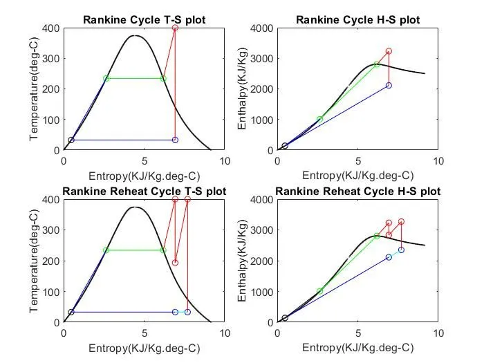
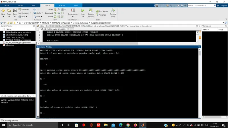
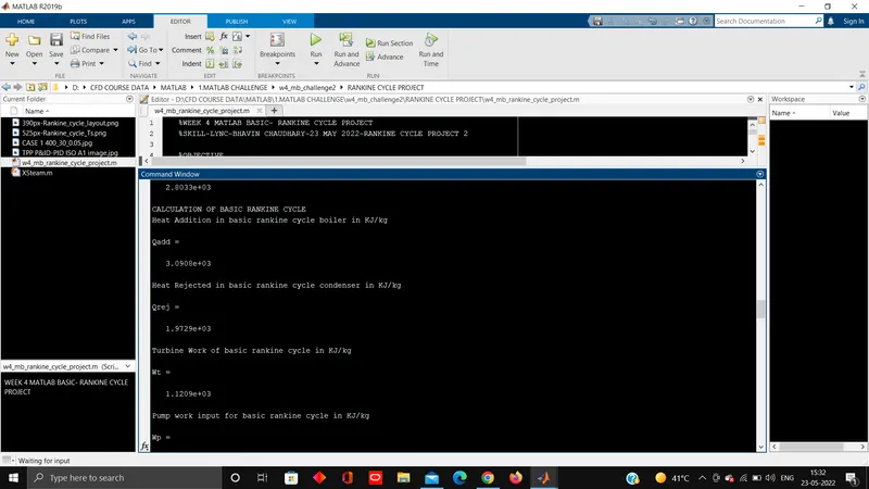
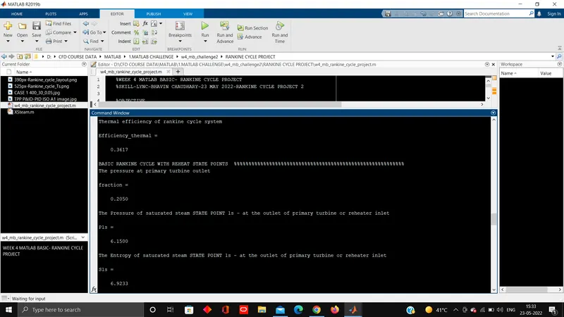
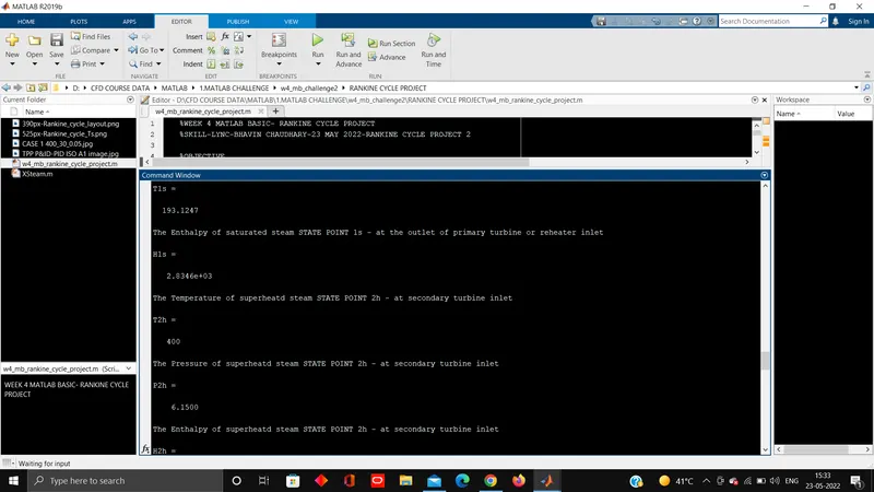
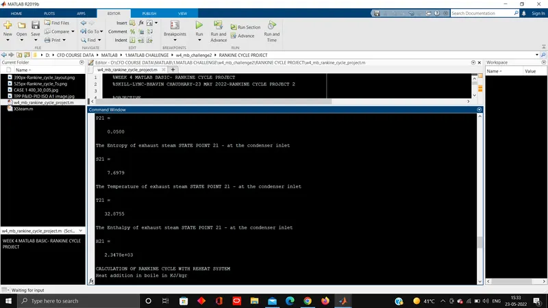
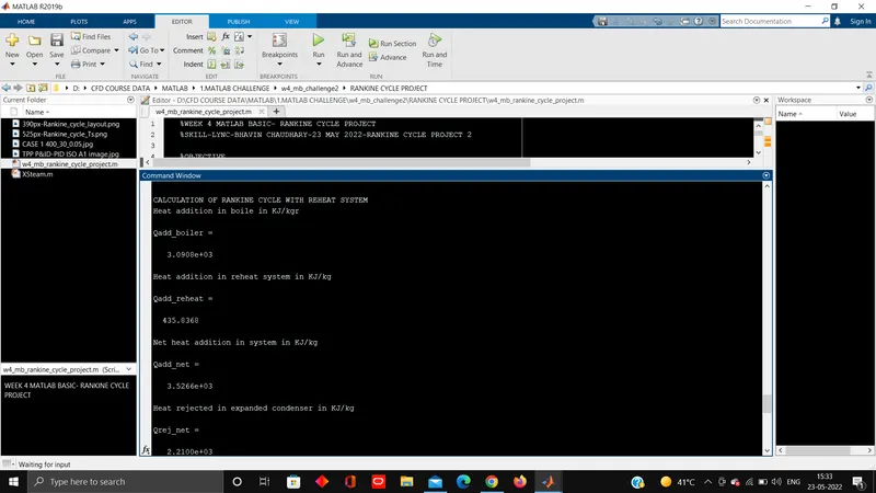
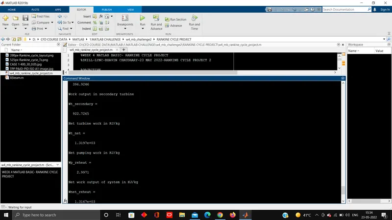
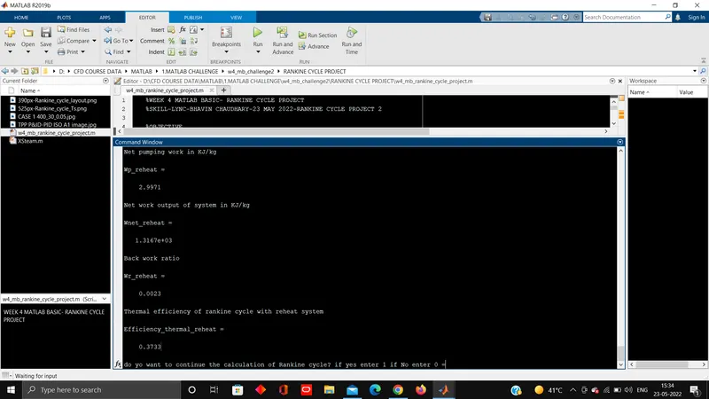
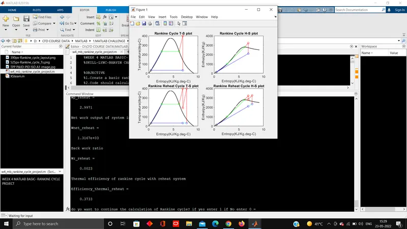
1.2 SCREENSHOTS
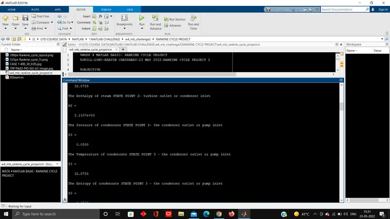
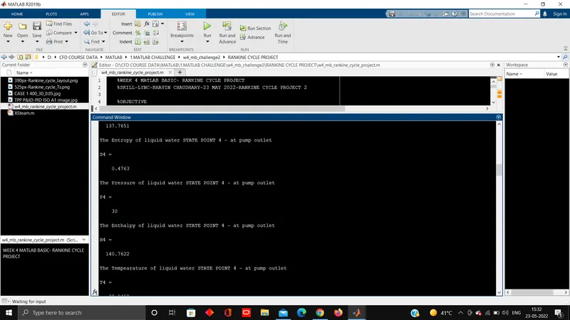
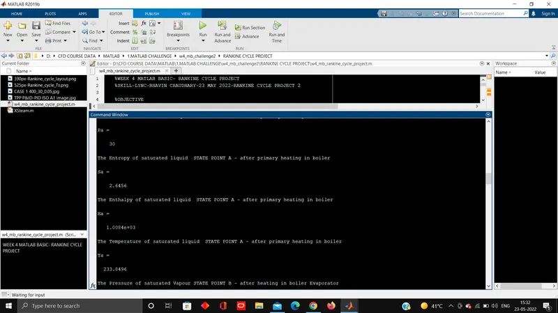
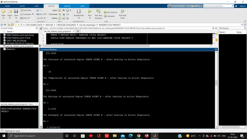
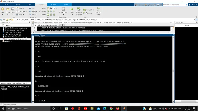
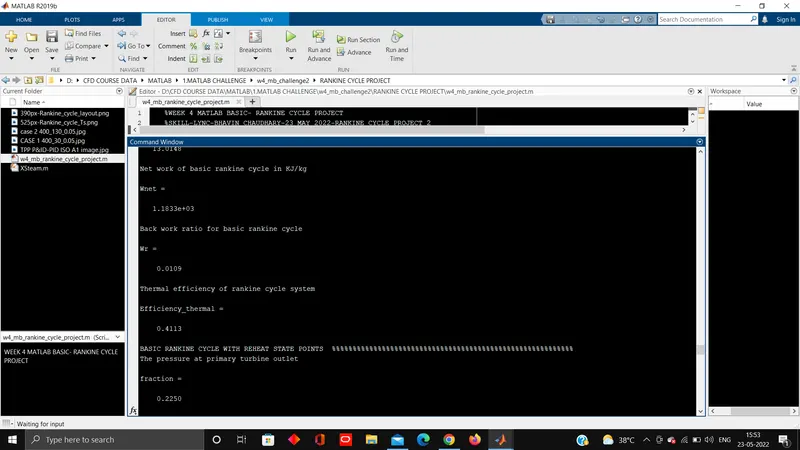
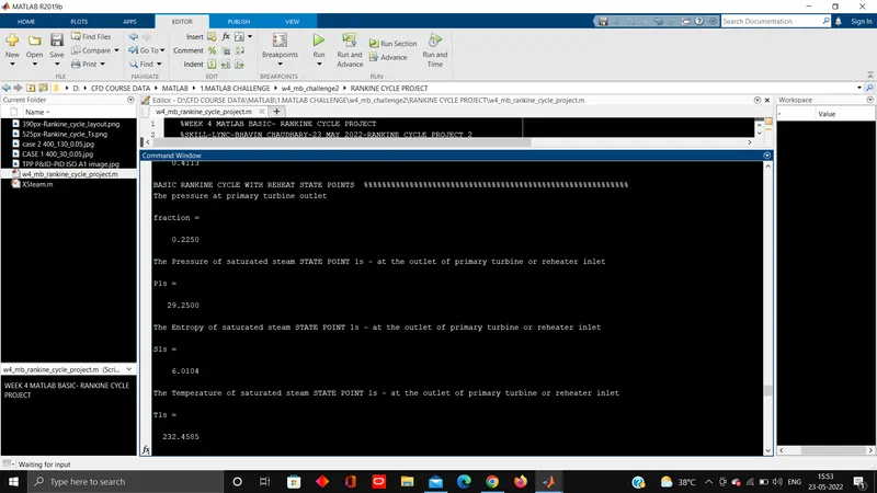
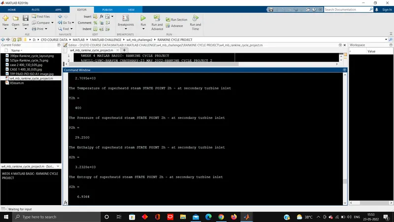
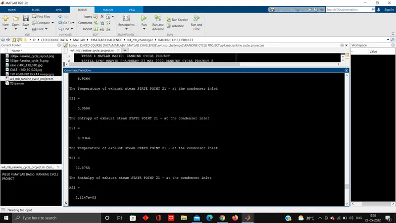
4. CASE 2 T1=400'C, P1=130 bar, P2=0.05 bar
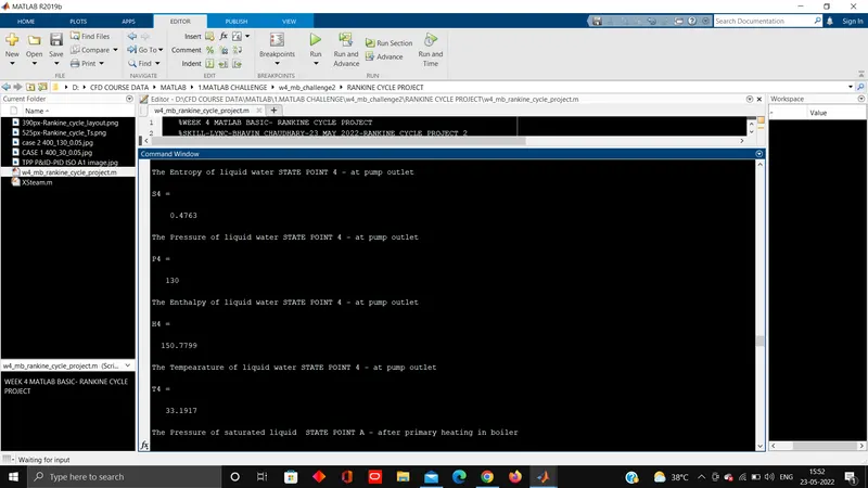
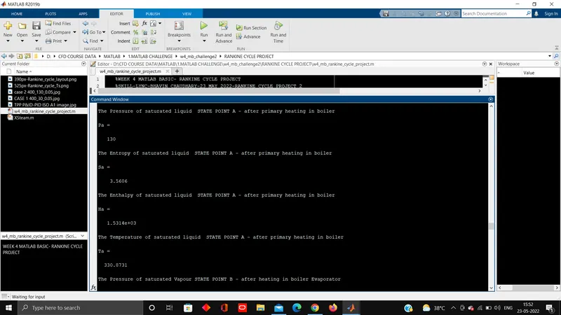
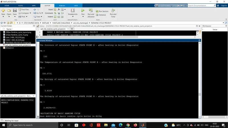
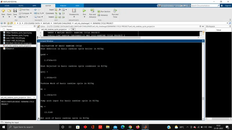
2.1 OUTPUT
do yo want to continue the calculation of Rankine cycle? if yes enter 1 if No enter 0 =1
BASIC RANKINE CYCLE STATE POINTS %%%%%%%%%%%%%%%%%%%%%%%%%%%%%%%%%%%%%%%%%%%%%%%%%%%%%%%%
enter the value of steam temperature at turbine inlet STATE POINT 1=400
T1 =
400
enter the value of steam pressure at turbine inlet STATE POINT 1=130
P1 =
130
Enthalpy of steam at turbine inlet STATE POINT 1
H1 =
3.0276e+03
Entropy of steam at turbine inlet STATE POINT 1
S1 =
6.0104
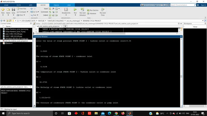
enter the value of steam pressure STATE POINT 2 - turbine outlet or condenser inlet=0.05
P2 =
0.0500
The entropy of steam STATE POINT 2 - condenser inlet
S2 =
6.0104
The temperature of steam STATE POINT 2 - Turbine oullet or condenser inlet
T2 =
32.8755
The Enthalpy of steam STATE POINT 2- turbine outlet or condenser inlet
H2 =
1.8313e+03
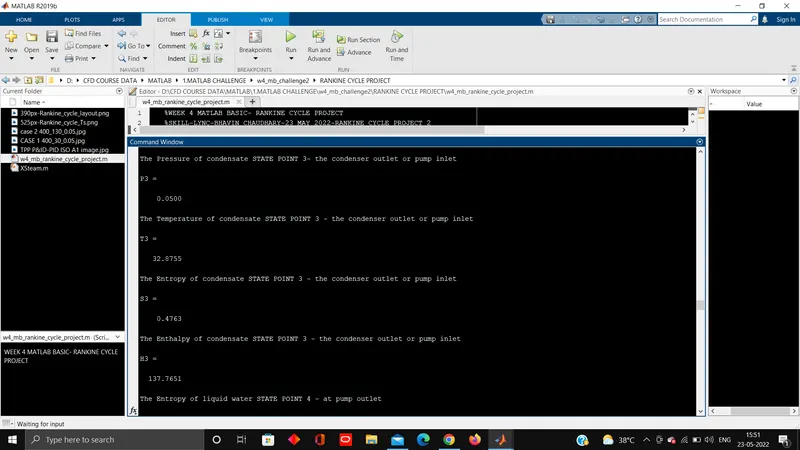
The Pressure of condensate STATE POINT 3- the condenser outlet or pump inlet
P3 =
0.0500
The Temperature of condensate STATE POINT 3 - the condenser outlet or pump inlet
T3 =
32.8755
The Entropy of condensate STATE POINT 3 - the condenser outlet or pump inlet
S3 =
0.4763
The Enthalpy of condensate STATE POINT 3 - the condenser outlet or pump inlet
H3 =
137.7651
The Entropy of liquid water STATE POINT 4 - at pump outlet
S4 =
0.4763
The Pressure of liquid water STATE POINT 4 - at pump outlet
P4 =
130
The Enthalpy of liquid water STATE POINT 4 - at pump outlet
H4 =
150.7799
The Tempearature of liquid water STATE POINT 4 - at pump outlet
T4 =
33.1917
The Pressure of saturated liquid STATE POINT A - after primary heating in boiler
Pa =
130
The Entropy of saturated liquid STATE POINT A - after primary heating in boiler
Sa =
3.5606
The Enthalpy of saturated liquid STATE POINT A - after primary heating in boiler
Ha =
1.5314e+03
The Temperature of saturated liquid STATE POINT A - after primary heating in boiler
Ta =
330.8731
The Pressure of saturated Vapour STATE POINT B - after heating in boiler Evaporator
Pb =
130
The Temperature of saturated Vapour STATE POINT B - after heating in boiler Evaporator
Tb =
330.8731
The Entropy of saturated Vapour STATE POINT B - after heating in boiler Evaporator
Sb =
5.4339
The Enthaply of saturated Vapour STATE POINT B - after heating in boiler Evaporator
Hb =
2.6629e+03
CALCULATION OF BASIC RANKINE CYCLE
Heat Addition in basic rankine cycle boiler in KJ/kg
Qadd =
2.8769e+03
Heat Rejected in basic rankine cycle condenser in KJ/kg
Qrej =
1.6936e+03
Turbine Work of basic rankine cycle in KJ/kg
Wt =
1.1963e+03
Pump work input for basic rankine cycle in KJ/kg
Wp =
13.0148
Net work of basic rankine cycle in KJ/kg
Wnet =
1.1833e+03
Back work ratio for basic rankine cycle
Wr =
0.0109
Thermal efficiency of rankine cycle system
Efficiency_thermal =
0.4113
BASIC RANKINE CYCLE WITH REHEAT STATE POINTS %%%%%%%%%%%%%%%%%%%%%%%%%%%%%%%%%%%%%%%%%%%%%%%%%%%%%%%%%%
The pressure at primary turbine outlet
fraction =
0.2250
The Pressure of saturated steam STATE POINT 1s - at the outlet of primary turbine or reheater inlet
P1s =
29.2500
The Entropy of saturated steam STATE POINT 1s - at the outlet of primary turbine or reheater inlet
S1s =
6.0104
The Temperature of saturated steam STATE POINT 1s - at the outlet of primary turbine or reheater inlet
T1s =
232.4585
The Enthalpy of saturated steam STATE POINT 1s - at the outlet of primary turbine or reheater inlet
H1s =
2.7095e+03
The Temperature of superheatd steam STATE POINT 2h - at secondary turbine inlet
T2h =
400
The Pressure of superheatd steam STATE POINT 2h - at secondary turbine inlet
P2h =
29.2500
The Enthalpy of superheatd steam STATE POINT 2h - at secondary turbine inlet
H2h =
3.2328e+03
The Entropy of superheatd steam STATE POINT 2h - at secondary turbine inlet
S2h =
6.9364
The Temperature of exhaust steam STATE POINT 2l - at the condenser inlet
P2l =
0.0500
The Entropy of exhaust steam STATE POINT 2l - at the condenser inlet
S2l =
6.9364
The Temperature of exhaust steam STATE POINT 2l - at the condenser inlet
T2l =
32.8755
The Enthalpy of exhaust steam STATE POINT 2l - at the condenser inlet
H2l =
2.1147e+03
CALCULATION OF RANKINE CYCLE WITH REHEAT SYSTEM
Heat addition in boile in KJ/kgr
Qadd_boiler =
2.8769e+03
Heat addition in reheat system in KJ/kg
Qadd_reheat =
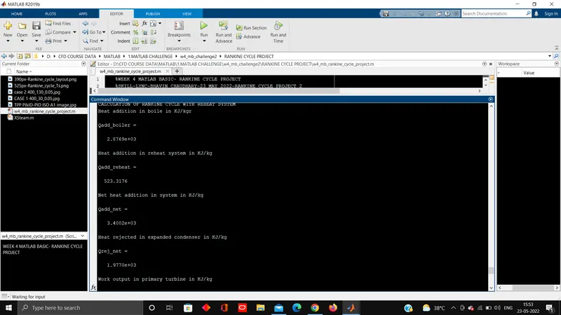
523.3176
Net heat addition in system in KJ/kg
Qadd_net =
3.4002e+03
Heat rejected in expanded condenser in KJ/kg
Qrej_net =
1.9770e+03
Work output in primary turbine in KJ/kg
Wt_primary =
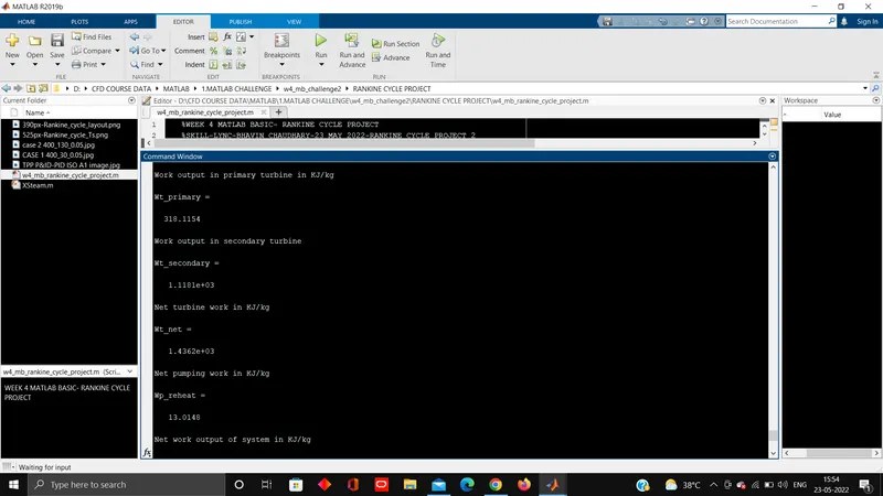
318.1154
Work output in secondary turbine
Wt_secondary =
1.1181e+03
Net turbine work in KJ/kg
Wt_net =
1.4362e+03
Net pumping work in KJ/kg
Wp_reheat =
13.0148
Net work output of system in KJ/kg
Wnet_reheat =
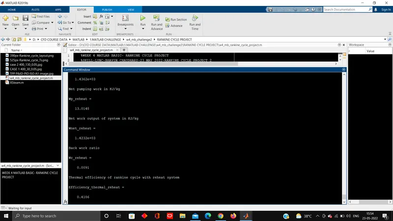
1.4232e+03
Back work ratio
Wr_reheat =
0.0091
Thermal efficiency of rankine cycle with reheat system
Efficiency_thermal_reheat =
0.4186
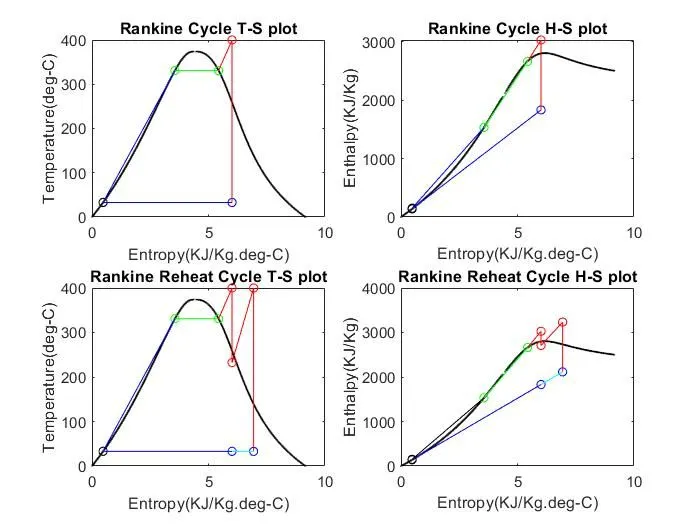
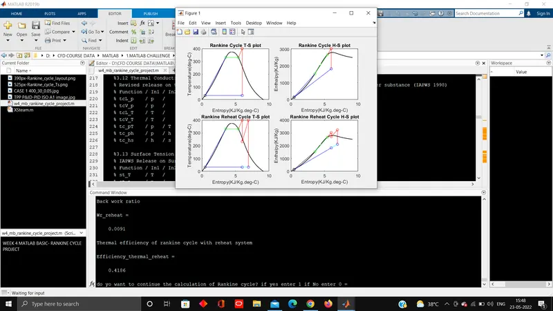
2.2 SCREENSHOTS
5. CASE 3 T1=400'C, P1=210 bar, P2=0.05 bar
3.1 OUTPUT
do yo want to continue the calculation of Rankine cycle? if yes enter 1 if No enter 0 =1
BASIC RANKINE CYCLE STATE POINTS %%%%%%%%%%%%%%%%%%%%%%%%%%%%%%%%%%%%%%%%%%%%%%%%%%%%%%%%
enter the value of steam temperature at turbine inlet STATE POINT 1=400
T1 =
400
enter the value of steam pressure at turbine inlet STATE POINT 1=210
P1 =
210
Enthalpy of steam at turbine inlet STATE POINT 1
H1 =
2.7780e+03
Entropy of steam at turbine inlet STATE POINT 1
S1 =
5.4807
enter the value of steam pressure STATE POINT 2 - turbine outlet or condenser inlet=0.05
P2 =
0.0500
The entropy of steam STATE POINT 2 - condenser inlet
S2 =
5.4807
The temperature of steam STATE POINT 2 - Turbine oullet or condenser inlet
T2 =
32.8755
The Enthalpy of steam STATE POINT 2- turbine outlet or condenser inlet
H2 =
1.6693e+03
The Pressure of condensate STATE POINT 3- the condenser outlet or pump inlet
P3 =
0.0500
The Temperature of condensate STATE POINT 3 - the condenser outlet or pump inlet
T3 =
32.8755
The Entropy of condensate STATE POINT 3 - the condenser outlet or pump inlet
S3 =
0.4763
The Enthalpy of condensate STATE POINT 3 - the condenser outlet or pump inlet
H3 =
137.7651
The Entropy of liquid water STATE POINT 4 - at pump outlet
S4 =
0.4763
The Pressure of liquid water STATE POINT 4 - at pump outlet
P4 =
210
The Enthalpy of liquid water STATE POINT 4 - at pump outlet
H4 =
158.7620
The Tempearature of liquid water STATE POINT 4 - at pump outlet
T4 =
33.3933
The Pressure of saturated liquid STATE POINT A - after primary heating in boiler
Pa =
210
The Entropy of saturated liquid STATE POINT A - after primary heating in boiler
Sa =
4.1093
The Enthalpy of saturated liquid STATE POINT A - after primary heating in boiler
Ha =
1.8894e+03
The Temperature of saturated liquid STATE POINT A - after primary heating in boiler
Ta =
369.8269
The Pressure of saturated Vapour STATE POINT B - after heating in boiler Evaporator
Pb =
210
The Temperature of saturated Vapour STATE POINT B - after heating in boiler Evaporator
Tb =
369.8269
The Entropy of saturated Vapour STATE POINT B - after heating in boiler Evaporator
Sb =
4.8062
The Enthaply of saturated Vapour STATE POINT B - after heating in boiler Evaporator
Hb =
2.3375e+03
CALCULATION OF BASIC RANKINE CYCLE
Heat Addition in basic rankine cycle boiler in KJ/kg
Qadd =
2.6193e+03
Heat Rejected in basic rankine cycle condenser in KJ/kg
Qrej =
1.5315e+03
Turbine Work of basic rankine cycle in KJ/kg
Wt =
1.1088e+03
Pump work input for basic rankine cycle in KJ/kg
Wp =
20.9969
Net work of basic rankine cycle in KJ/kg
Wnet =
1.0878e+03
Back work ratio for basic rankine cycle
Wr =
0.0189
Thermal efficiency of rankine cycle system
Efficiency_thermal =
0.4153
BASIC RANKINE CYCLE WITH REHEAT STATE POINTS %%%%%%%%%%%%%%%%%%%%%%%%%%%%%%%%%%%%%%%%%%%%%%%%%%%%%%%%%%
The pressure at primary turbine outlet
fraction =
0.2450
The Pressure of saturated steam STATE POINT 1s - at the outlet of primary turbine or reheater inlet
P1s =
51.4500
The Entropy of saturated steam STATE POINT 1s - at the outlet of primary turbine or reheater inlet
S1s =
5.4807
The Temperature of saturated steam STATE POINT 1s - at the outlet of primary turbine or reheater inlet
T1s =
265.7355
The Enthalpy of saturated steam STATE POINT 1s - at the outlet of primary turbine or reheater inlet
H1s =
2.5342e+03
The Temperature of superheatd steam STATE POINT 2h - at secondary turbine inlet
T2h =
400
The Pressure of superheatd steam STATE POINT 2h - at secondary turbine inlet
P2h =
51.4500
The Enthalpy of superheatd steam STATE POINT 2h - at secondary turbine inlet
H2h =
3.1940e+03
The Entropy of superheatd steam STATE POINT 2h - at secondary turbine inlet
S2h =
6.6320
The Temperature of exhaust steam STATE POINT 2l - at the condenser inlet
P2l =
0.0500
The Entropy of exhaust steam STATE POINT 2l - at the condenser inlet
S2l =
6.6320
The Temperature of exhaust steam STATE POINT 2l - at the condenser inlet
T2l =
32.8755
The Enthalpy of exhaust steam STATE POINT 2l - at the condenser inlet
H2l =
2.0216e+03
CALCULATION OF RANKINE CYCLE WITH REHEAT SYSTEM
Heat addition in boile in KJ/kgr
Qadd_boiler =
2.6193e+03
Heat addition in reheat system in KJ/kg
Qadd_reheat =
659.7612
Net heat addition in system in KJ/kg
Qadd_net =
3.2790e+03
Heat rejected in expanded condenser in KJ/kg
Qrej_net =
1.8838e+03
Work output in primary turbine in KJ/kg
Wt_primary =
243.8344
Work output in secondary turbine
Wt_secondary =
1.1724e+03
Net turbine work in KJ/kg
Wt_net =
1.4162e+03
Net pumping work in KJ/kg
Wp_reheat =
20.9969
Net work output of system in KJ/kg
Wnet_reheat =
1.3952e+03
Back work ratio
Wr_reheat =
0.0148
Thermal efficiency of rankine cycle with reheat system
Efficiency_thermal_reheat =
0.4255
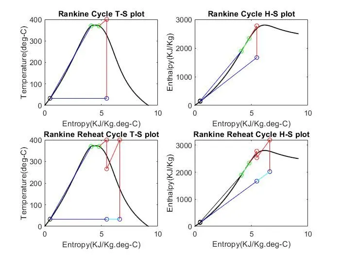
3.2 SCREENSHOTS
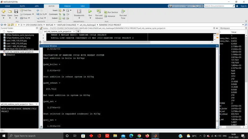
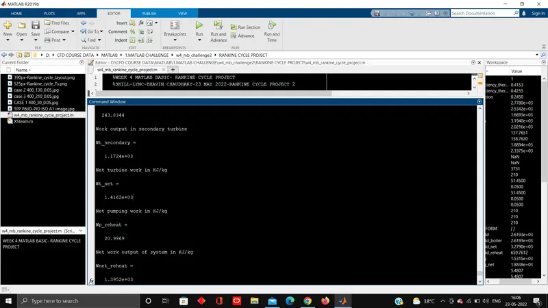
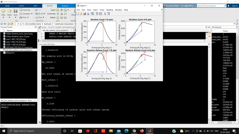
6. CASE 4 T1=800'C, P1=210 bar, P2=0.05 bar
4.1 OUTPUT
do yo want to continue the calculation of Rankine cycle? if yes enter 1 if No enter 0 =1
BASIC RANKINE CYCLE STATE POINTS %%%%%%%%%%%%%%%%%%%%%%%%%%%%%%%%%%%%%%%%%%%%%%%%%%%%%%%%
enter the value of steam temperature at turbine inlet STATE POINT 1=800
T1 =
800
enter the value of steam pressure at turbine inlet STATE POINT 1=210
P1 =
210
Enthalpy of steam at turbine inlet STATE POINT 1
H1 =
4.0630e+03
Entropy of steam at turbine inlet STATE POINT 1
S1 =
7.0273
enter the value of steam pressure STATE POINT 2 - turbine outlet or condenser inlet=0.05
P2 =
0.0500
The entropy of steam STATE POINT 2 - condenser inlet
S2 =
7.0273
The temperature of steam STATE POINT 2 - Turbine oullet or condenser inlet
T2 =
32.8755
The Enthalpy of steam STATE POINT 2- turbine outlet or condenser inlet
H2 =
2.1425e+03
The Pressure of condensate STATE POINT 3- the condenser outlet or pump inlet
P3 =
0.0500
The Temperature of condensate STATE POINT 3 - the condenser outlet or pump inlet
T3 =
32.8755
The Entropy of condensate STATE POINT 3 - the condenser outlet or pump inlet
S3 =
0.4763
The Enthalpy of condensate STATE POINT 3 - the condenser outlet or pump inlet
H3 =
137.7651
The Entropy of liquid water STATE POINT 4 - at pump outlet
S4 =
0.4763
The Pressure of liquid water STATE POINT 4 - at pump outlet
P4 =
210
The Enthalpy of liquid water STATE POINT 4 - at pump outlet
H4 =
158.7620
The Tempearature of liquid water STATE POINT 4 - at pump outlet
T4 =
33.3933
The Pressure of saturated liquid STATE POINT A - after primary heating in boiler
Pa =
210
The Entropy of saturated liquid STATE POINT A - after primary heating in boiler
Sa =
4.1093
The Enthalpy of saturated liquid STATE POINT A - after primary heating in boiler
Ha =
1.8894e+03
The Temperature of saturated liquid STATE POINT A - after primary heating in boiler
Ta =
369.8269
The Pressure of saturated Vapour STATE POINT B - after heating in boiler Evaporator
Pb =
210
The Temperature of saturated Vapour STATE POINT B - after heating in boiler Evaporator
Tb =
369.8269
The Entropy of saturated Vapour STATE POINT B - after heating in boiler Evaporator
Sb =
4.8062
The Enthaply of saturated Vapour STATE POINT B - after heating in boiler Evaporator
Hb =
2.3375e+03
CALCULATION OF BASIC RANKINE CYCLE
Heat Addition in basic rankine cycle boiler in KJ/kg
Qadd =
3.9042e+03
Heat Rejected in basic rankine cycle condenser in KJ/kg
Qrej =
2.0048e+03
Turbine Work of basic rankine cycle in KJ/kg
Wt =
1.9205e+03
Pump work input for basic rankine cycle in KJ/kg
Wp =
20.9969
Net work of basic rankine cycle in KJ/kg
Wnet =
1.8995e+03
Back work ratio for basic rankine cycle
Wr =
0.0109
Thermal efficiency of rankine cycle system
Efficiency_thermal =
0.4865
BASIC RANKINE CYCLE WITH REHEAT STATE POINTS %%%%%%%%%%%%%%%%%%%%%%%%%%%%%%%%%%%%%%%%%%%%%%%%%%%%%%%%%%
The pressure at primary turbine outlet
fraction =
0.2450
The Pressure of saturated steam STATE POINT 1s - at the outlet of primary turbine or reheater inlet
P1s =
51.4500
The Entropy of saturated steam STATE POINT 1s - at the outlet of primary turbine or reheater inlet
S1s =
7.0273
The Temperature of saturated steam STATE POINT 1s - at the outlet of primary turbine or reheater inlet
T1s =
521.5821
The Enthalpy of saturated steam STATE POINT 1s - at the outlet of primary turbine or reheater inlet
H1s =
3.4832e+03
The Temperature of superheatd steam STATE POINT 2h - at secondary turbine inlet
T2h =
800
The Pressure of superheatd steam STATE POINT 2h - at secondary turbine inlet
P2h =
51.4500
The Enthalpy of superheatd steam STATE POINT 2h - at secondary turbine inlet
H2h =
4.1372e+03
The Entropy of superheatd steam STATE POINT 2h - at secondary turbine inlet
S2h =
7.7322
The Temperature of exhaust steam STATE POINT 2l - at the condenser inlet
P2l =
0.0500
The Entropy of exhaust steam STATE POINT 2l - at the condenser inlet
S2l =
7.7322
The Temperature of exhaust steam STATE POINT 2l - at the condenser inlet
T2l =
32.8755
The Enthalpy of exhaust steam STATE POINT 2l - at the condenser inlet
H2l =
2.3583e+03
CALCULATION OF RANKINE CYCLE WITH REHEAT SYSTEM
Heat addition in boile in KJ/kgr
Qadd_boiler =
3.9042e+03
Heat addition in reheat system in KJ/kg
Qadd_reheat =
653.9950
Net heat addition in system in KJ/kg
Qadd_net =
4.5582e+03
Heat rejected in expanded condenser in KJ/kg
Qrej_net =
2.2205e+03
Work output in primary turbine in KJ/kg
Wt_primary =
579.7787
Work output in secondary turbine
Wt_secondary =
1.7789e+03
Net turbine work in KJ/kg
Wt_net =
2.3587e+03
Net pumping work in KJ/kg
Wp_reheat =
20.9969
Net work output of system in KJ/kg
Wnet_reheat =
2.3377e+03
Back work ratio
Wr_reheat =
0.0089
Thermal efficiency of rankine cycle with reheat system
Efficiency_thermal_reheat =
0.5129
do yo want to continue the calculation of Rankine cycle? if yes enter 1 if No enter 0 =0
you have exited from the program
>>
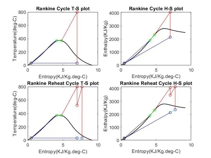
4.2 SCREENSHOTS
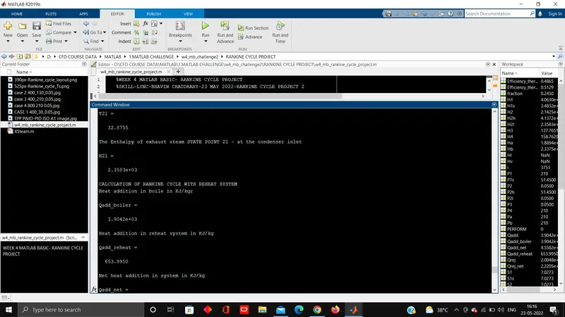
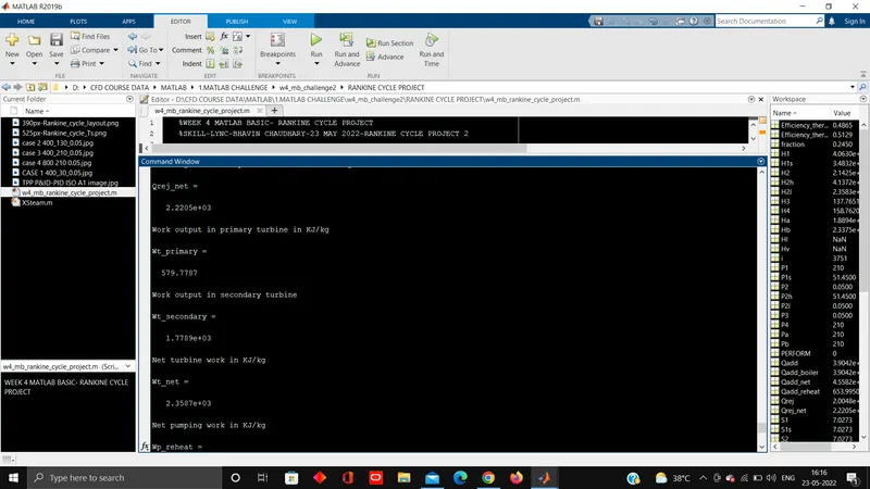
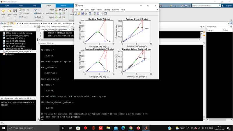
7. OBSERVATION
1. Increasing the turbine inlet temperature, the efficiency of rankine cycle increases.
2. Increasing the turbine inlet pressure, efficiency of rankine cycle increases.
3. The efficiency of reheat rankine cycle is higher than basic rankine cycle.
For higher temperature 800'C and high pressure 210 bar or high the ideal efficiency of rankine cycle attained is 48% approx. and with reheat system we canachieve 51% approx.
8. CONCLUSION
The maximum ideal efficiency of rankine cycle with reheating system can be achieved upto 51 % approx.
9. CITATION OR REFERENCES
1.X Steam, Thermodynamic properties of water and steam- https://www.mathworks.com/matlabcentral/fileexchange/9817-x-steam-thermodynamic-properties-of-water-and-steam
2.Book- Engineering Thermodynamics-Fourth Edition-Author PK Nag-Tata McGraw-Hill Publication-Chapter 12 Vapour power
3.Book- Steam Table-Fouth Edition-Author C P Kothandaraman-New Age International Publishers
4.Book- steam Table with Moillers Diagram- Author R S Khurmi-S Chand Publication
5.Xsteam table -From skill-lync challenge google drive link
6.Book-Power Plant Engineering-Third Edition-Author PK Nag-Tata McGraw-Hill Publication-Chapter 2-Analysis of Steam Cycle
7.Book-Power Plant Engineering-Fourth Edition-Author-HG Katariya & JP Hadiya-Books India Publication- Chapter 2-High Pressure Boiler ,Chapter-4 Draught System, Chapter-5 Condenser & Cooling Tower
8.Self Draw the P&ID of basic Thermal Power Plant -using AUTODESK Autocad Plant-3D Software
9.WIKIPEDIA-Rankine cycle - https://en.wikipedia.org/wiki/Rankine_cycle