Project 2 - Rankine cycle Simulator
OBJECTIVE :
- To simulate a rankine cycle using matlab.
- Extracting steam and water properties from XStream data.
- Calculating all the state points of te cycle based on user inputs.
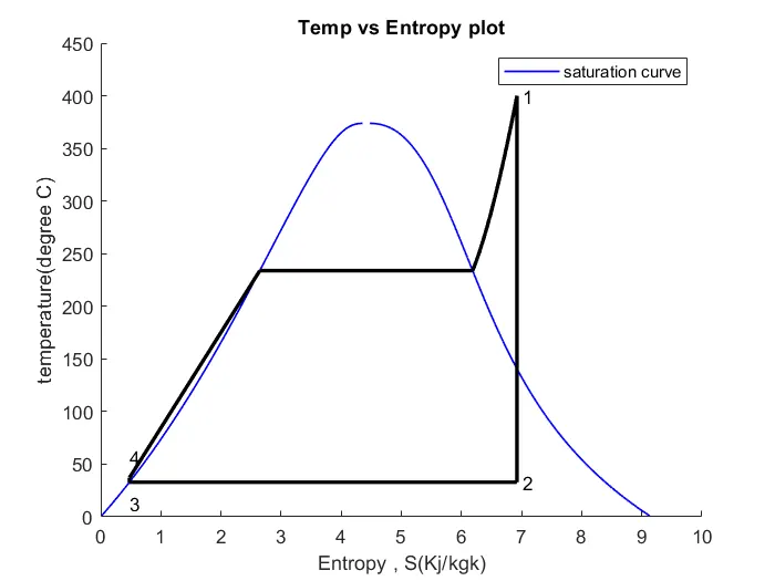
- Calculating the T-S and h-s plot for the given input.
Rankine cycle :
- Rankine cycle is an idealized thermodynamic cycle or heat engine in which a fuel is used to produce heat within boiler converting water into steam which then expands through a turbine producing useful work.This process was developed in 1859 by scottish engineer William.J.M.Rankine. It is a cycle converts heat into mechanical energy which usally is converted into electrical energy.
- In this project an idealized cycle is simulated.Hence neglecting losses.
- Rankine cycle is derived out of carnot cycle its power depends on the temperature difference between the heat source and a cold source.
- The efficiency of rankine cycle is limited by high heat of vaporization of the working fluid.Also useless the pressure and temperature reach super critical levels in the steam boiler the temperature range the cycle can operate over is quite small. Steam turbine entry temperature are typically around 565 degree celcius.
- While many substances could be used as working fluid in the Rankine cycle water is usally the fluid of choice due to its favourable properties such as its non-toxic and unreactive chemistry,abundance and low cost as well as in thermodynamic properties.
- By condensing the working steam vapour to a liquid the pressure at the turbine outlet is lowered and the energy required by the feed pump consumes only 1% - 3% of the turbine output power.
Four stages in Rankine cycle:
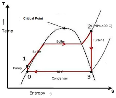
- Process 1-2: The working fluid is pumped from low to high pressure. As the fluid is a liquid at this stage the pump requires little input energy. In other words it is Isentropic compression.
- Process 2-3 : The high pressure liquid enters a boiler where it is heated at constant pressure by an external heat source to become a dry saturated vapour. it is constant pressure heat addition in boiler.
- process 3-4 : The dry saturated vapour expands through turbine generating power.This decreases the temperature and pressure of the vapour and some condensation may occur. this is isentropic expansion.
- Process 4-1 : The wet vapour then enters a condenser where it is condensed at a constant pressuer to become a saturated liquid. it is constant pressure heat rejection condenser.
MATLAB CODE:
clear all
close all
clc

%%
disp('RANKINE CYCLE')
disp('1-2 is isentropic Expansion in the turbine');
disp('2-3 is constant pressure heat removal in condenser');
disp('3-4 is isentropic compression in pump ');
disp('4-1 is  constant pressure heat addition in the boiler');

%%
%obtaining the data
p1 = input('nValue of pressure at turbine inlet,p1(in bar)= ');
T1 = input('nValue of temperature at turbine inlet,T1(in degree.C) = ');
p2 = input('nValue of temperature at condenser inlet,p2(in bar)= ');

%% Extracting data
% state 1
h1 = XSteam('h_pT',p1,T1);
s1 = XSteam('s_pT',p1,T1);

%state 2
s2 = s1;
sf2 = XSteam('sL_p',p2);
sg2 = XSteam('sV_p',p2);
x2 = (s2 - sf2)/(sg2 - sf2);
hf2 = XSteam('hL_p',p2);
hg2 = XSteam('hV_p',p2);
h2 = hf2 + (x2*(hg2-hf2));

%state 3
p3 = p2;
s3 = XSteam('sL_p',p3);
h3 = XSteam('hL_p',p3);

%state 4
s4 = s3 ;
p4 = p1;

%work done by turbine
Wt = h1 -h2;

%work done to run pump
v3 = XSteam('vL_p', p3);
Wp = v3*(p4-p3)*100;
h4 = h3 + Wp;

%net work
Wnet = Wt - Wp;

%heat into the system
Qin = h1- h4;

%heat out of the system
Qout = h2 - h3;

%Thermal efficiency
eff = (Wnet/Qin)*100;

%specific steam consumption
SSC = (3600/Wnet);

%% calculating temperatures at state points
T3 = XSteam('Tsat_p',p3);
T2 = T3;
Cp4 = XSteam('Cp_ps',p4,s4);
Cv4 = XSteam('Cv_ps',p4,s4);
k = Cp4/Cv4;
T4 = T3/((p3/p4)^((k-1)/k));

%calculating temperature, entropy and enthalpy at vapour and liquid
T6 = XSteam('Tsat_p',p1);
s5 = XSteam('sL_p',p1);
s6 = XSteam('sV_p',p1);
h5 = XSteam('hL_p',p1);
h6 = XSteam('hV_p',p1);
T5 = T6;

%%plotting the saturation curve
T = linspace(1,375,1000);
for i = 1:length(T)
    sf(i) = XSteam('sL_T',T(i));
    sg(i) = XSteam('sV_T',T(i));
    hf(i) = XSteam('hL_T',T(i));
    hg(i) = XSteam('hV_T',T(i));
end

%plotting T-s diagram
figure(1)
hold on
plot(sf, T,'b','linewidth',1)
plot(sg,T,'b','linewidth',1)
plot([s1 s2],[T1 T2],'k','linewidth',2)
plot([s2 s3],[T2 T3],'k','linewidth',2)
plot([s3 s4],[T3 T4],'k','linewidth',2)
plot([s4 s5],[T4 T5],'k','linewidth',2)
plot([s5 s6],[T5 T6],'k','linewidth',2)

sc1 = linspace(s6,s1,1000);
for l = 1:length(sc1)
    Tc1(l) = XSteam('T_ps',p1,sc1(l));
end

plot(sc1,Tc1,'k','linewidth',2)
text(s1+0.1,T1,'1')
text(s2+0.1,T2,'2')
text(s3,T3-20,'3')
text(s4,T4+20,'4')
title('Temp vs Entropy plot')
xlabel('Entropy , S(Kj/kgk)')
ylabel('temperature(degree C)')
legend('saturation curve')

%% plotting h-s diagram
figure(2)
hold on
plot(sf,hf,'b','linewidth',1)
plot(sg,hg,'b','linewidth',1)
plot([s1 s2],[h1 h2], 'k','linewidth',2)
plot([s2 s3],[h2 h3], 'k','linewidth',2)
plot([s3 s4],[h3 h4], 'k','linewidth',2)
hc = linspace(h4,h5,100);
for k = 1:length(hc)
    sch(k) = XSteam('s_ph',p1,hc(k));
end
plot(sch,hc,'k','linewidth',2)
plot([s4 s1],[h4 h1],'k','linewidth',2)
for m = 1:length(sc1)
    hc1(m) = XSteam('h_ps',p1,sc1(m));
end
plot(sch,hc,'k','linewidth',2)
text(s1+0.1,h1,'1')
text(s2+0.1,h2,'2')
text(s3,h3-100,'3')
text(s4,h4+200,'4')
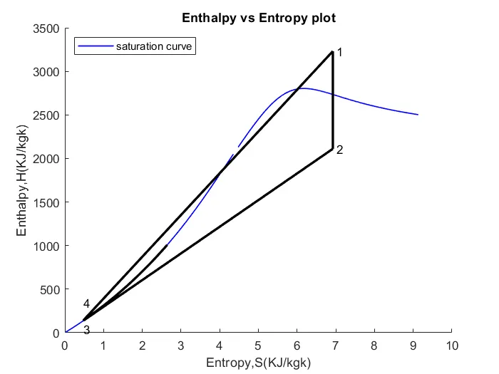
title('Enthalpy vs Entropy plot')
xlabel('Entropy,S(KJ/kgk)')
ylabel('Enthalpy,H(KJ/kgk)')
legend('saturation curve','location','northwest')

%% Displaying Results
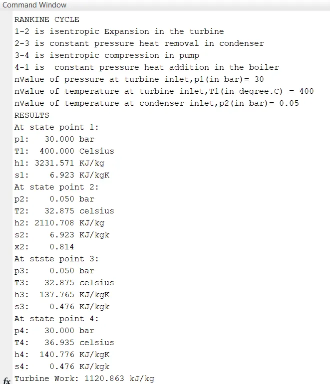
disp('RESULTS')
fprintf('At state point 1:\n');
fprintf('p1: %8.3f bar\n', p1);
fprintf('T1: %8.3f Celsius\n', T1);
fprintf('h1: %8.3f KJ/kg\n', h1);
fprintf('s1: %8.3f KJ/kgK\n', s1);
% Displaying state point 2
fprintf('At state point 2:\n');
fprintf('p2: %8.3f bar\n',p2);
fprintf('T2: %8.3f celsius\n',T2);
fprintf('h2: %8.3f KJ/kg\n',h2);
fprintf('s2: %8.3f KJ/kgk\n',s2);
fprintf('x2: %8.3f\n',x2);
%Displaying state point 3
fprintf('At stste point 3:\n');
fprintf('p3: %8.3f bar\n',p3);
fprintf('T3: %8.3f celsius\n',T3);
fprintf('h3: %8.3f KJ/kgK\n',h3);
fprintf('s3: %8.3f KJ/kgk\n',s3);
%Displaying state point 4
fprintf('At state point 4:\n');
fprintf('p4: %8.3f bar\n',p4);
fprintf('T4: %8.3f celsius\n',T4);
fprintf('h4: %8.3f KJ/kgK\n',h4);
fprintf('s4: %8.3f KJ/kgk\n',s4);

fprintf('Turbine Work: %8.3f kJ/kg \n',Wt);
fprintf('Pump work: %8.3 kJ/kgn \n',Wp)
fprintf('Wnet: %8.3f kJ/kgn\n',Wnet)
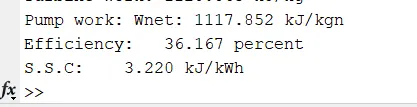
fprintf('Efficiency: %8.3f percent \n',eff);
fprintf('S.S.C: %8.3f kJ/kWh\n',SSC);
CODE EXPLANATION:
- XSteam data is used to extract steam and water properties of enthalpy ,entropy at specific pressure and temperature for saturated liquid ,saturated vapour conditions etc.
- The program requires the input of pressure at stae point1 , Temperature at state point 1 and Temperature at condenser inlet at point 2
- With the help of these inlets and from XSteam data the program calculates all the state points of the rankiene cycle.
- h1 = XSteam('h_pT',p1,T1);(Returns the enthalpy of water at given pressure and teperature in bar and degree C)
- As we extract the data we use thermodynamic relation relation to further stae points and extract their data from XSteam
- f and g stands for saturated liquid and saturated vapour respectively.
- Efficiency and specific steam consumption (SSC) is calculated.
- saturated curve is plotted in blue for saturated liquid and saturated gas.
- Plot of T vs s and h vs s is created from all the point obtained from the code.
- The varies as the use input varies.
- Results are displayed in command window.
RESULTS:
plot for Enthalpy vs Entropy
Plot Temperature vs Entropy
Results in command window