Project 2 - Rankine cycle Simulator
Aim:
1) To Develop a basic program that calculates the state points
2) To add the thermodynamic relation to get the points in between the state variables.
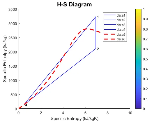
3) To plot Rankine cycle on T-s and H-s curve.
Theory
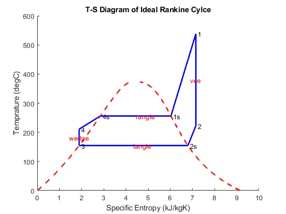
The Rankine cycle is the fundamental operating cycle of all power plants where an operating fluid is continuously evaporated and condensed. The selection of operating fluid depends mainly on the available temperature range. Figure 1 shows the idealized Rankine cycle. The Rankine cycle operates in the following steps:
The Rankine cycle is the fundamental operating cycle of all power plants where an operating fluid is continuously evaporated and condensed. The selection of operating fluid depends mainly on the available temperature range. Figure 1 shows the idealized Rankine cycle. The Rankine cycle operates in the following steps:
1-2 Isentropic Expansion. The vapor is expanded in the turbine, thus producing work that may be converted to electricity. In practice, the expansion is limited by the temperature of the cooling medium and by the erosion of the turbine blades by liquid entrainment in the vapor stream as the process moves further into the two-phase region. Exit vapor qualities should be greater than 90% to increase the life of the turbine blade.
2-3 Isobaric Heat Rejection. The vapor-liquid mixture leaving the turbine (2) is condensed at low pressure, usually in a surface condenser using cooling water. In well designed and maintained condensers, the pressure of the vapor is well below atmospheric pressure, approaching the saturation pressure of the operating fluid at the cooling water temperature.
3-4 Isentropic Compression. The pressure of the condensate is raised in the feed pump. Because of the low specific volume of liquids, the pump work is relatively small and often neglected in thermodynamic calculations.
4-1 Isobaric Heat Transfer. High-pressure liquid enters the boiler from the feed pump (4) and is heated to saturation temperature. Further addition of energy causes evaporation of the liquid until it is fully converted to saturated steam (1).
The efficiency of power cycles is defined as
Matlab code:
Xsteam is function to get steam data
Main code:
clear all
close all
clc

fprintf('       SIMULATOR OF RANKINE CYCLE  nn')
fprintf('1-2  Isentropic Expansion in the Turbinen')
fprintf('2-3  Constant Pressure Heat Rejection by the Condensern')
fprintf('3-2  Isentropic Compression in the Pumpn')
fprintf('4-1  Constant Pressure Heat Addition by the Boilernn')


%inputs
P1 = input('Enter the Pressure at the Turbine Inlet (in bar): ');
T1 = input('Enter the Temperature at the Turbine inlet (in Degree celsius): ');
P2 = input('Enter the Pressure at the Condenser (in bar): ');
disp('   RESULTS')
%getting Cp and cv values from Xsteam
%Cp and Cv assumed to  not change with temperature to make problem simple
% for vapur
high_cpV= XSteam('CpV_p', P1);
low_cpV=XSteam('CpV_p', P2);
high_cvV=XSteam('CvV_p', P1);
low_cvV=XSteam('CvV_p', P2);


% for liquid
high_cpL= XSteam('CpL_p', P1);
low_cpL=XSteam('CpL_p', P2);
high_cvL=XSteam('CvL_p', P1);
low_cvL=XSteam('CvL_p', P2);


%Getting important parameters from Xsteam
%for high pressure
T1s = XSteam('Tsat_p', P1);
S1g = XSteam('sV_p', P1);
S1f = XSteam('SL_p', P1);
S1fg = S1g - S1f;
H1f = XSteam('hL_p', P1);
H1g = XSteam('hV_p', P1);
H1fg = H1g - H1f;
%for low pressure
S2g = XSteam('sV_p', P2);
S2f = XSteam('SL_p', P2);
S2fg = S2g - S2f;
T2s = XSteam('Tsat_p', P2);
H2f = XSteam('hL_p', P2);
H2g = XSteam('hV_p', P2);
H2fg = H2g - H2f;


%% State point 1

disp('At state point 1:')

fprintf('P1 is : %f Barn', P1)

fprintf('T1 is : %f Deg celsiusn', T1)

H1 = XSteam('h_pt', P1, T1);
fprintf('H1 is : %f kJ/kgn', H1)

S1 = XSteam('s_pt', P1, T1);
fprintf('S1 is : %f kJ/kgKnn', S1)

%% State point 2

disp('At state point 2:')

fprintf('P2 is : %f Barn', P2)    %P2 input already taken

S2 = S1;
fprintf('S2 is : %f kJ/kgKn', S2)
%predicting location of point 2 in T-s
if(S2<=S2g)
    X2 = (S2 - S2f) / (S2fg);   % Dryness Fraction at state point 2
else
    X2=1;
end
fprintf('X2 is :%f n', X2)
%calculating T2 for superheat or wet or dry wherever it lies
if(X2<1)
    T2=T2s;
else
    %t2 cal by s2=s2g+low_cpV*(log(T2/T2s))
    T2=(T2s+273.15)*exp((S2-S2g)/low_cpV) ; %2 in superheated region
    T2=T2-273.15;
end
fprintf('T2 is : %f Deg celsius n', T2)

if(X2<1)
   H2 = H2f + X2 * H2fg;
else
   H2=H2g+ low_cpV*(T2-T2s);
end
fprintf('H2 is : %f kJ/kgn', H2)

%% State point 3
%Assuming no subcooling in condensor
disp('At state point 3:')

P3 = P2;
fprintf('P3 is : %f Barn', P3)

V3 = XSteam('vL_p', P3);

T3 = T2s;    %no subcooling assumed
fprintf('T3 is : %f Deg celsiusn', T3)

H3 =H2f;
fprintf('H3 is : %f kJ/kgn', H3)

S3 =S2f;
fprintf('S3 is : %f kJ/kgKnn', S3)

%% State point 4
disp('At state point 4:')

P4 = P1;
fprintf('P4 is : %f Barn', P4)

S4 = S3;
fprintf('S4 is : %f kJ/kgKn', S4)

Wp = V3 * (P4 - P3) * 100;
H4 = Wp + H3;
fprintf('H4 is : %f kJ/kgn', H4)


% to cal T4 s4=s3=sf1-high_cpL*ln(t1s/t4)
term=exp((S1f-S4)/high_cpL);  %Use exp instead of Exp to take input as double
T4= T1s/term;
fprintf('T4 is : %f Deg celsius nn', T4)

%% Work done, heat, SSC and efficiency calculations
Wt = H1 - H2;
fprintf('Work by turbine is : %f kJ/kgn', Wt)
fprintf('Work by compressor is : %f kJ/kgn', Wp)
Wnet = Wt - Wp;
fprintf('Net Wok done is : %f kJ/kgn', Wnet)
Qin = H1 - H4;
eff_thermal = Wnet / Qin ;    % Effieciency
fprintf('Thermal efficiency is : %f', eff_thermal); disp('%')
SSC = 3600 / Wt;    % Specific steam consuption
fprintf('S.S.C is : %f kg/kWh ', SSC)

%% Calculation for plotting Liquid and Vapour lines
%
% <<FILENAME.PNG>>
%
temp = linspace(1, 373, 500);
for i = 1 : length(temp)
     H_L(i) = XSteam('hL_T', temp(i));
     H_V(i) = XSteam('hV_T', temp(i));
     S_L(i) = XSteam('sL_T', temp(i));
     S_V(i) = XSteam('sV_T', temp(i));
end

%% Ploting T - S and H - S Diagrams

figure(1) % T-S
hold on
plot([S1 S2], [T1 T2], 'b', 'linewidth', 2)
text(S1,T1,' 1')
text(S2,T2,' 2')
plot([S2 S2g], [T2 T2s], 'b', 'linewidth', 2)
text(S2g,T2s,' 2s')
plot([S2g S3], [T2s T3], 'b', 'linewidth', 2)
text(S3,T3,' 3')
plot([S3 S4], [T3 T4], 'b', 'linewidth', 2)
text(S4,T4,' 4')
plot([S4 S1f], [T4 T1s], 'b', 'linewidth', 2)
text(S1f,T1s,' 4s')
plot([S1f S1g], [T1s T1s], 'b', 'linewidth', 2)
text(S1g,T1s,' 1s')
plot([S1g S1], [T1s T1], 'b', 'linewidth', 2)
plot(S_L, temp, 'r', 'linestyle','--','linewidth', 2)
plot(S_V, temp, 'r', 'linestyle','--','linewidth', 2)
%marking direction
text(S1,(T1+T2)/2,'vee','HorizontalAlignment','center','color','r')
text((S2g+S2f)/2,T3,'langle','color','r')
text(S3,(T3+T4)/2,'wedge','HorizontalAlignment','center','color','r')
text((S1f+S1g)/2,T1s,'rangle','color','r')
title('T-S Diagram of Ideal Rankine Cylce')
ylabel('Temprature (degC)')
xlabel('Specific Entropy (kJ/kgK)')

figure(2) % H-S
hold on
plot([S1 S2], [H1 H2], 'b', 'linewidth', 1);
text(S1,H1,' 1')
plot([S2 S3], [H2 H3], 'b', 'linewidth', 1);
text(S2,H2,' 2')
plot([S3 S4], [H3 H4], 'b', 'linewidth', 1);
text(S3,H3,' 3')
plot([S4 S1], [H4 H1], 'b', 'linewidth', 1);
text(S4,H4,' 4')
plot(S_L, H_L, 'r','linestyle','--', 'linewidth', 2.5)
plot(S_V, H_V, 'r','linestyle','--', 'linewidth', 2.5)
title('H-S Diagram', 'FontSize', 15)
ylabel('Specific Enthalpy (kJ/kg)')
xlabel('Specific Entropy (kJ/kgK)')
Results:
       SIMULATOR OF RANKINE CYCLE  nn1-2  Isentropic Expansion in the Turbinen2-3  Constant Pressure Heat Rejection by the Condensern3-2  Isentropic Compression in the Pumpn4-1  Constant Pressure Heat Addition by the BoilernnEnter the Pressure at the Turbine Inlet (in bar): 30
Enter the Temperature at the Turbine inlet (in Degree Celsius): 400
Enter the Pressure at the Condenser (in bar): 0.05
   RESULTS
At state point 1:
P1 is : 30.000000 BarnT1 is : 400.000000 Deg celsiusnH1 is : 3231.571027 kJ/kgnS1 is : 6.923259 kJ/kgKnnAt state point 2:
P2 is : 0.050000 BarnS2 is : 6.923259 kJ/kgKnX2 is :0.814256 nT2 is : 32.875490 Deg celsius nH2 is : 2110.708212 kJ/kgnAt state point 3:
P3 is : 0.050000 BarnT3 is : 32.875490 Deg celsiusnH3 is : 137.765119 kJ/kgnS3 is : 0.476254 kJ/kgKnnAt state point 4:
P4 is : 30.000000 BarnS4 is : 0.476254 kJ/kgKnH4 is : 140.776056 kJ/kgnT4 is : 147.599058 Deg celsius nnWork by turbine is : 1120.862815 kJ/kgnWork by compressor is : 3.010937 kJ/kgnNet Wok done is : 1117.851878 kJ/kgnThermal efficiency is : 0.361671%
S.S.C is : 3.211811 kg/kWh >> 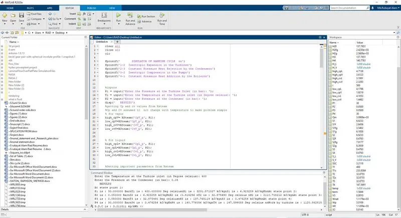
plates: