Project 2 - Modeling of 3 phase Induction Motor Drive
Question 1:
Aim:
Model 3 Phase Inverter using Simulink using 3 phase Squirrel Cage Induction motor, using V/F method
Design inputs:
- Power = 100 HP
- DC Voltage = 800 V
- Output Voltage = 460 VRMS – line to line
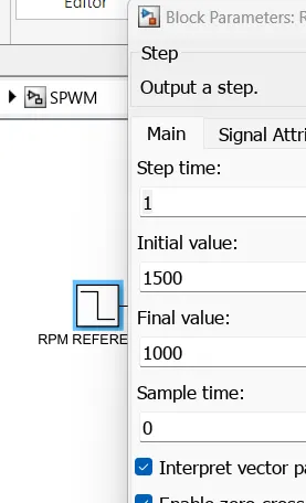
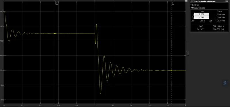
- Initial Speed = 1500 RPM
- Final Speed = 1000 RPM
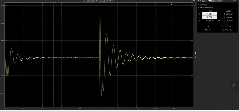
- Initial Load Torque = 10 Nm
- Final Torque=20 Nm
- Torque Step Time = 0.1 secs
Theory:
The V/f method is a form of scalar control because it relies only on the magnitude of the stator voltage. The stator flux can be maintained constant by keeping the V/f ratio constant.The V/f method only controls the speed of the machine. The machine will naturally adjust its torque to the load or to reference but there is no explicit torque control.
The V/f method is a form of scalar control because it relies only on the magnitude of the stator voltage. This contrasts with vector control methods that use both the magnitude and the phase.
In the stator flux reference frame, the equation of the stator circuit is:
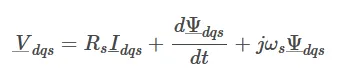
In steady-state, it becomes
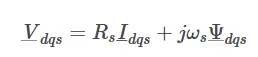
If we neglect the voltage drop over the stator resistance and consider only the magnitude:
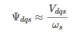
Consequently, the stator flux can be maintained constant by keeping the V/f ratio constant. In this case, the speed of the machine becomes proportional to the stator voltage.
Schematics:
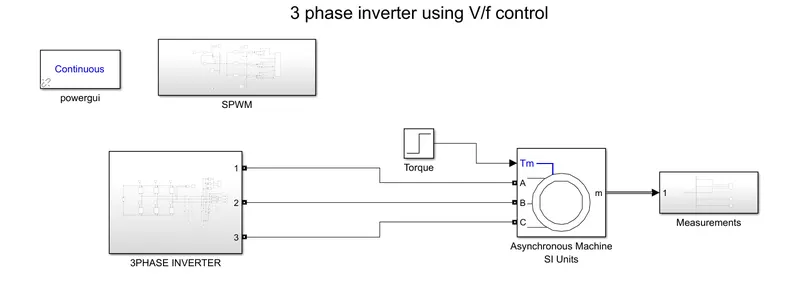
Each of the block is expanded and attached:
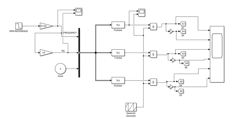
SPWM:
Speed reference
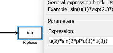
Reference R phase:
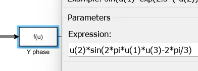
Reference Y phase:
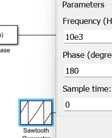
Switching frequency:
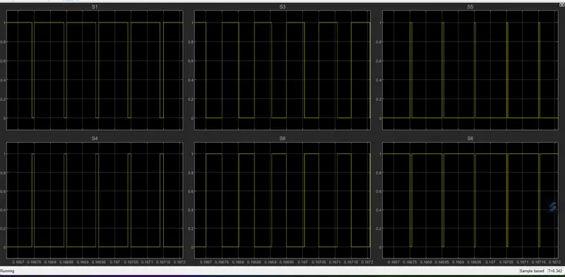
PWM Pulses
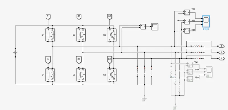
3 Phase inverter:
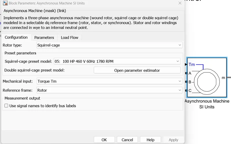
Asynchronous machine
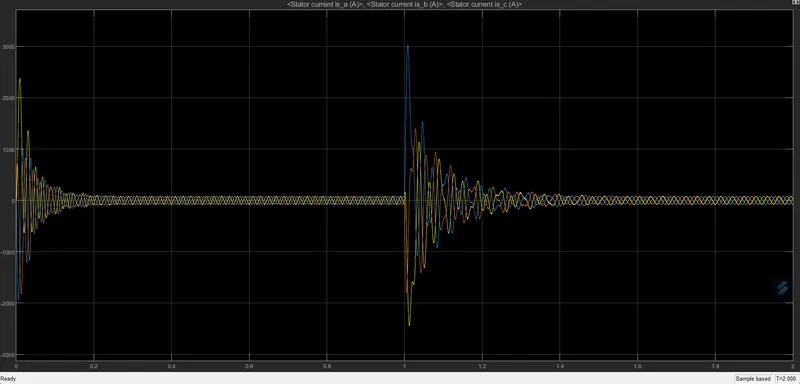
Stator Current
Speed in rpm:
Torque in Nm:
Question no 2:
Aim:
To derive the transfer function of 3 phase Induction Motor
Derivations:
The expression for motor torque is given by:
`T_(em) = (pMphi_ri_(sd))/L_r`
where P is pole pairs
M is mutual inductance
`phi_r` is rotor flux
`i_(sd)`is stator d axis current
`L_r` is rotor inductance
The rotor flux rotates with a syn speed of `omega_s`, the electric equation is given by:
`V_(sd) =R_si_(sd) + (dphi_(sd))/(dt)-omega_sphi_(sq)`
`V_(sq) = R_si_(sq)+ (dphi_(sq))/(dt) + omega_sphi_(sd)`
`0 =R_ri_(rd)+(dphi_r)/dt`
`0 = R_ri_(rq) +(omega_s - p(d theta)/dt)phi_r`
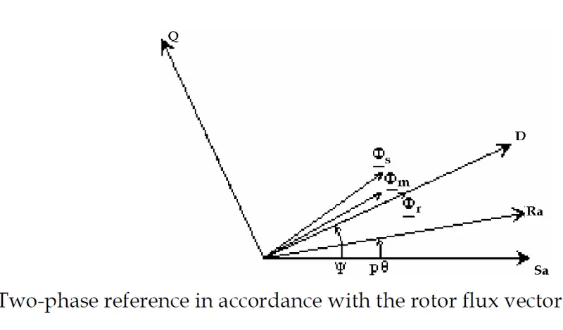
The stator voltages & the stator fluxes expressions can be written using complex representation `bar X = x_d+j.x_q`:
`bar(V_s) = R_sbar(I_s) + (dphi_s)/(dt) + j.omega_sbar(phi_s)`
`bar(phi_s) = L_sbar(I_s) + Mbar(I_r)`
By adding and subtracting the term`M^2/L_r *bar(I_s)` in the stator flux vector expression, the magnetizing rotor current vector is introduced `bar(I_(mr))` :
`bar(phi_s) = sigmaL_sbar(I_s) + M^2/L_r(bar(I_s)+L_r/M*bar(I_r))`
`= sigmaL_sbar(I_s) + M^2/L_r*bar(I_(mr))`
Since the rotor flux vector is aligned on the magnetizing rotor current vector:`bar(phi_r) = phi_r =L_rbar(I_r) + M*bar(I_(s))= M*bar(I_(mr))`, the stator flux vector can be written as a function of the stator:
`bar(phi_s)= sigmaL_sbar(I_s) + M/L_r*phi_r`
Substituting the above in stator voltage:
`bar(V_s) = R_sbar(I_s) + sigmaL_s(dbar(I_s))/(dt) +M/L_r*(dphi_r)/(dt) + j.omega_sbar(phi_s)`
Rotor voltages:
`0 = R_ri_(rd)+(dphi_r)/(dt)`
`0 = R_ri_(rq)+omega_(r)phi_(r)`
Rotor currents:
`i_(rd) = phi_r/L_r - M/L_ri_(sd);`
`i_(rq) = -M/L_ri_(sq)`
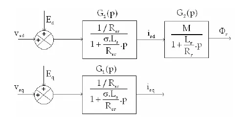
The inputs of the transfer functions are `V_(sd)` and `V_(sq)` , and the outputs the variables that determine the motor torque `phi_r` and `i_(sd)`.
Transfer functions on D axis:
It is possible to control the rotor flux via the stator current on the D axis. This can be demonstrated from the rotor electric equation on the D axis:
`(dphi_r)/(dt) = -R_r/L_rphi_r+R_rM/L_ri_(sd)`
From the stator voltage equation:
`v_(sd) = R_si_(sd)+sigmaL_s(di_(sd))/(dt)+M/L_r(dphi_r)/(dt)-omega_sphi_(sq)`
Now,
`phi_(sq) = L_si_(sq)+Mi_(rq) = L_si_(sq)-M^2/L_ri_(sq)`
`= (L_s-M^2/L_r)i_(sq) = L_s(1-M^2/(L_rL_s))i_(sq)`
`= L_ssigmai_(sq)`
`=> v_(sd) = R_si_(sd) + sigmaL_s(di_(sd))/(dt)+M/L_r(dphi)/(dt)-omega_sL_ssigmai_(sq)`
`v_(sd) = R_(sr)i_(sd)+sigmaL_s(di_(sd))/(dt)+E_d`
where `R_(sr) = R_s+R_r(M/L_r)^2`
`E_d = -R_rM/L_r^2phi_r-omega_sL_ssigmai_(sq)`
Similar, stator voltage on q axis can be given by:
`v_(sq) = R_(sr)i_(sq)+sigmaL_s(di_(sq))/(dt)+E_q`
`E_d`& `E_q`represents the coupling between the two axes D & Q.
The transfer function is given by:
For further undertsnding, refer the paper attached.
Question no 3
Aim:
Model 3 phase induction motor with a 3 phase inverter using Direct Torque control
Design inputs:
- Initial Speed = 0 RPM
- Flux Target = 2.5 webers
- DC Voltage = 500 V;
- Fundamental Frequency = 60 Hz
- Speed Step Time = 0.01 secs
- Determine fundamental speed based upon fundamental frequency
- Determine the switching sequence for direct torque control
- Moment of Inertia = 0.1 Kgm^2
- Load Torque Initial = 0 Nm
- Final Load Torque = 50 Nm
- Torque Step Time = 0.03 secs
Theory:
Vector control (also referred to as field oriented control, or FOC) controls the magnetizing and the torque-producing components of the stator current independently to control both motor speed and torque.
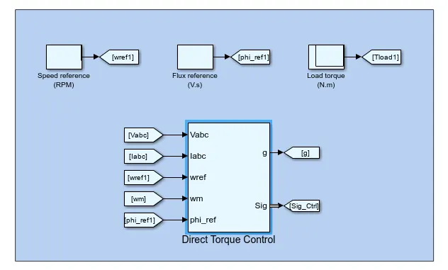
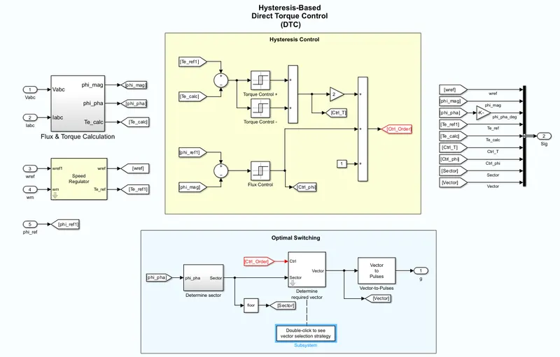
Another control method, known as direct torque control (DTC), is similar to field oriented control, in that it decouples torque and flux and controls them independently. But DTC controls motor torque directly, without a modulator, so torque response is much faster.
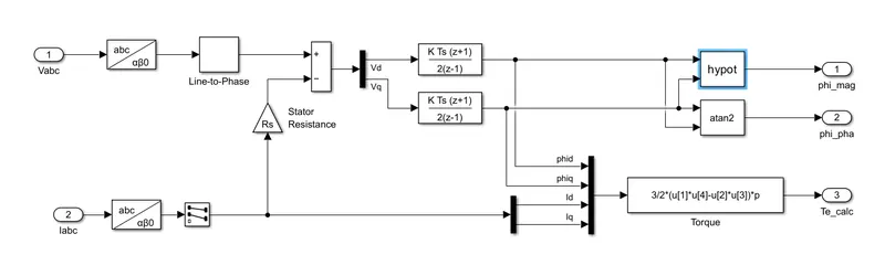
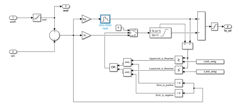
Direct torque control uses two control loops — a speed control loop and a torque control loop — that work together, along with an advanced motor model, to precisely predict stator flux and motor torque.
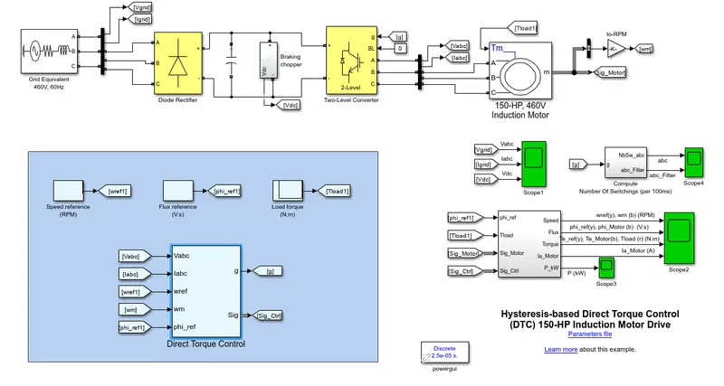
Schematics:
Power Circuit:
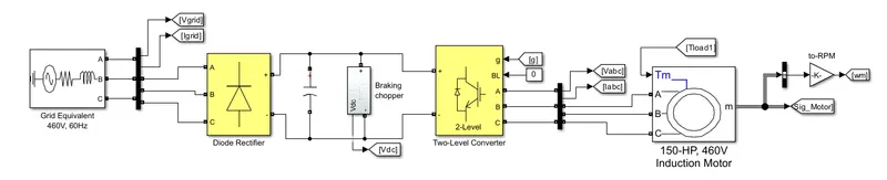
As shown, the power circuit consists of grid with frequency 60Hz and 480V which is then fed to a diode rectifier which converts AC to DC. This DC is then fed to the 2 level IGBT convertor via a DC capacitor & braking chopper. The regulated voltage is then fed to the 3phase Induction motor.
The torque & frequency is then controlled by Direct Torque Control method
Flux & torque calculations:
Speed regulation
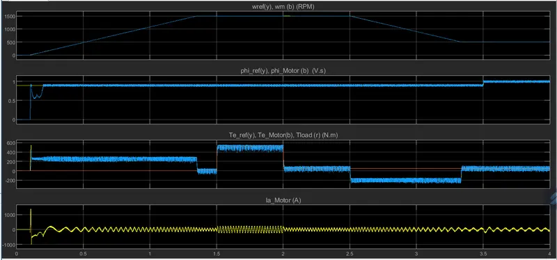
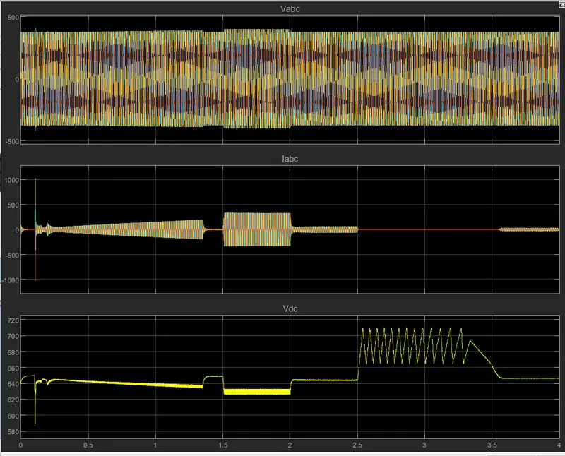
Various graphs are as follows:
2 Level inverter voltage & current output
Motor parameters: