Project - 2 - Meshing on the suspension Assembly
AIM : For the given CAD of an assembly, GEOMETRICAL CLEANUP is to be done post which is followed by SHELL MESHING and the same is to be assigned as a CLOSED VOLUME which is to be VOLUME MESHED using TETRA ELEMENTS and also the necessary connections is to be made using ANSA.
REAR WHEEL ASSEMBLY :
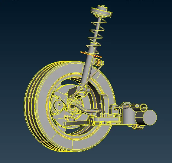
The GIVEN CAD is one half of the REAR WHEEL ASSEMBLY, which is to be completed using symmetry at the later stages.
The REAR WHEEL ASSEMBLY includes an axle assembly, which is designed as per the requirement i.e, FRONT WHEEL DRIVE or REAR WHEEL DRIVE, whose main role is to carry the LOAD of the VEHICLE and also helps to translate it ( NON ROTATING PART ) provided which drive it is. The REAR AXLE of the both the rear wheels also known as HALF SHAFTS are connected by means of a DIFFERENTIAL in a casing, which is provided in order to achieve different relative speed during TURNING of the VEHICLE.
There are generally four types of REAR AXLE :
- Live REAR AXLE ( solid drive axle) : Drive type
- Independent REAR DRIVE AXLE : Drive type
- Solid REAR AXLE : NON Drive type
- Independent REAR AXLE : NON Drive type
The two ends of the REAR AXLE are fitted into the wheel hubs of the two REAR WHEELS. IN includes plenty of parts named Axle housing, wheel rims, Bushes, shoes etc.
The ASSEMBLY provided is shown as follows;
WORKING PROCEDURE :
- TOPOLOGICAL CLEANUP :
- The imported CAD is run with geometry check using CHECKS > GEOMETRY.
- The following were the issues shown by it;
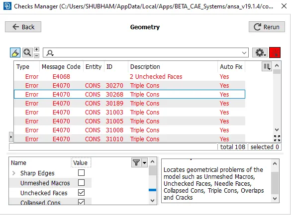
- The above shown issues has been fixed by AUTOFIXATION as well as MANUAL INTERVENTION. With all the issues cleared, the model is then forwarded for PID assignment.
- PIDs ALLOCATION :
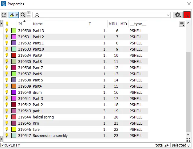
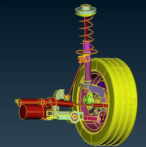
- Several numbers of components has been identified and assigned with an unique PID using SET PID > MANUAL.
- The result came is shown as follows ;
- SHELL MESHING :
- The assembly provided has several different subcomponents, some having uniform thickness throughout, and some having varying thickness and a spring which has to be converted as 1D element.
- All the different kinds has to treated differently and individually in order to properly capture the features of the component.
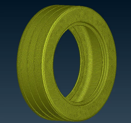
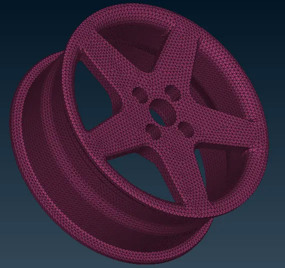
- Starting with the TYRE and RIM as these are the components having non uniform thickness, the MESH PARAMETERS and QUALITY CRITERIA assigned are different for these two and the element has to be used are TRIAs. The same is fed and as shown below;
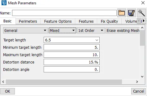
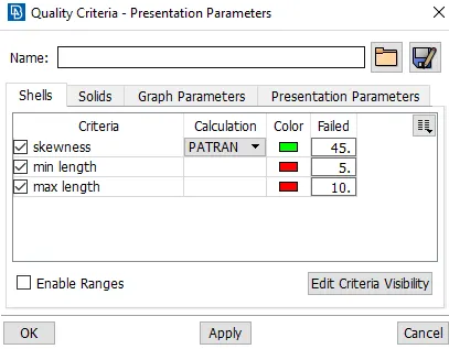
- The surface meshing operation is followed by necessary defeaturing in order to reduce failing element and also for feature capturing.
- The element used are TRIA for plane surface and for curved ones ORTHO TRIA for better capturing of feature and also for OPTIMISED PROCESSING TIME.
- In 2D MESH Deck the mesh is generated using MESH GENERATION > SPOT MESH.
- For refining the grids RECONSTRUCTION, SMOOTH and GRIDS > MOVE has been used.
- The GRIDS > ALIGN is also used in order to align the grids with the feature line. Shown below;
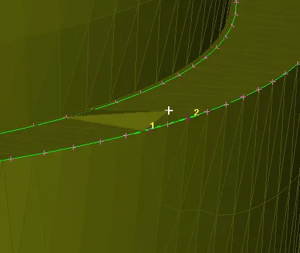
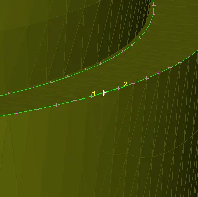
- The final outcome of surface meshed TYRE and RIM are shown below;
- Getting forward, now we will go with the 2D meshing of the components having uniform thickness < 5mm.
- The MESH PARAMETERS and QUALITY CRITERIA provided for these components are different than the former thus has been treated individually.
- First, Mid Surfacing has been done for the above said component. The operation is done using FACES > OFFSET and FACES > MIDDLE.
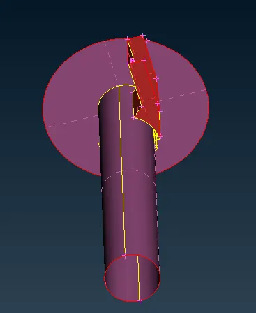
- The extracted midsurface is then connected using FACES > TOPO and also by FACES > EXTEND.
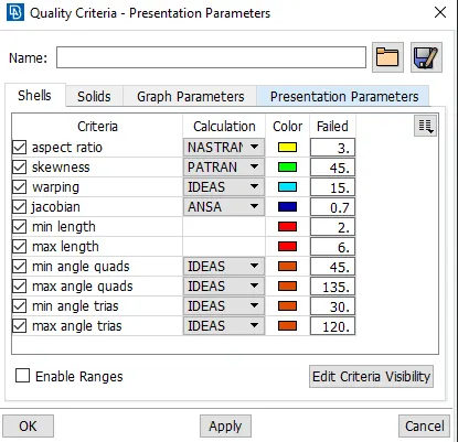
- The stitched MIDSURFACE is then taken forward for 2D MESHING after feeding the respective MESH PARAMETER and QUALITY CRITERIA. Shown below;
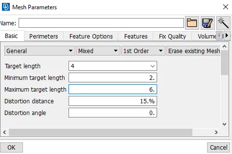
- The meshing is done manually using MESH GENERATION > BEST MESH.
- For refining the grids RECONSTRUCTION and SMOOTH operation has also been performed in order to get better MESH FLOW and to reduce TRIAs near holes and perims.
- The final MESHED result is shown below;
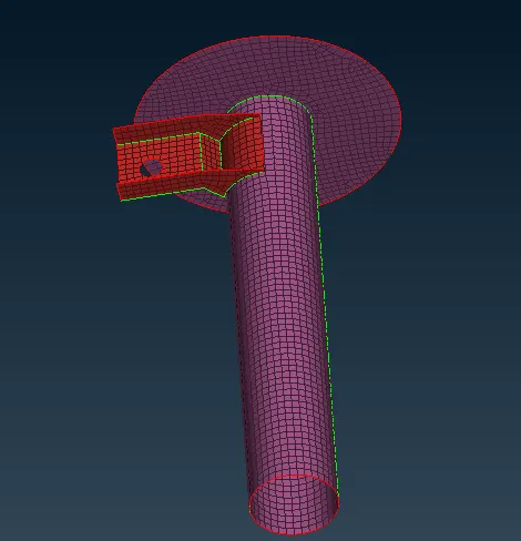
- Now we will perform 2D MESHING over the component having non uniform thickness.
- Majority of the component falls into this category, for which different MESH PARAMETERS and QUALITY CRITERIA has been assiigned, given as follows;
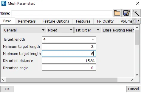
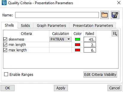
- Individually each of the component has been treated individually in order to SURFACE MESH.
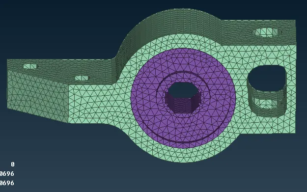
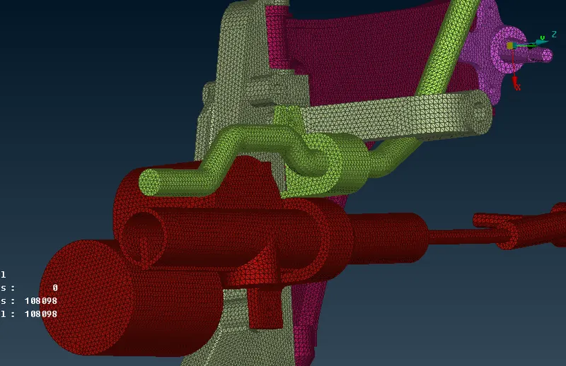
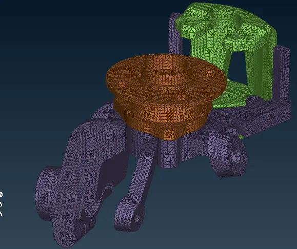
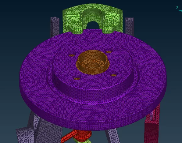
- The MESHED component has been shown as follows;
- The SUSPENSION SPRING is now to be converted as a 1D element using PBAR.
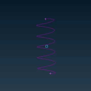
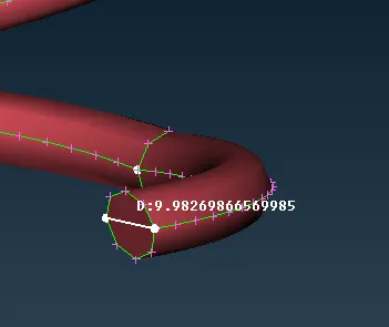
- At first the CURVE is extracted using CURVE > MIDDLE. And a point is also created by selecting the curve using POINTS > ONCOG in TOPO DECK. The wire dia is recorded ~ 10mm. Shown below;

- The next step is to go to NASTRAN DECK and select the CBAR in ELEMENTS.
- when selecting the curve and the node with respect to which it will be oriented the following dialogue shows;
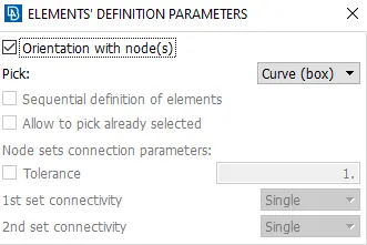
- The above dialogue has the options named CURVE BOX, that is to be set and the ORIENTATION WITH NODE is to be enabled.
- By RShift+? we can feed the radius which was found to be 5mm and the rest of the calculation will be automatically done by ANSA. Shown below;
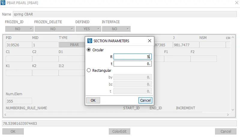
- As we click OK, a property card is formed and assigned and can be checked and modified in property card menu.
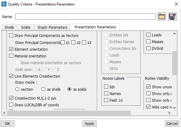
- In order to see the PBAR element we need to enable LINE ELEMENT CROSS SECTION > AS SOLIDS in PRESENTATION PARAMETERS of QUALITY CRITERIA. Shown below;
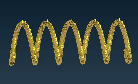
- The SUSPENSION SPRING as PBAR element can be seen as follows;
- So far all the SHELL MESHING has been done for the whole assembly. Now taking the model further for VOLUME MESHING.
- VOLUME MESHING :
- Before proceeding further we need to make sure that the entities are a closed volume, and thenafter it has to be assigned as a volume first in order to volume mesh.
- Aforesaid can be done by, VOLUMES > DEFINE > MANUAL. using this individually all the parts EXCEPT SUSPENSION SPRING and the COMPONENT HAVING THICKNESS < 5mm, has been assigned as a volume and a PID is also created.
- The volume assignment can be seen in VOLUME > LIST.
- Moving further, the QUALITY CRITERIA for the VOLUME MESHING has been fed. Shown below;
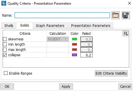
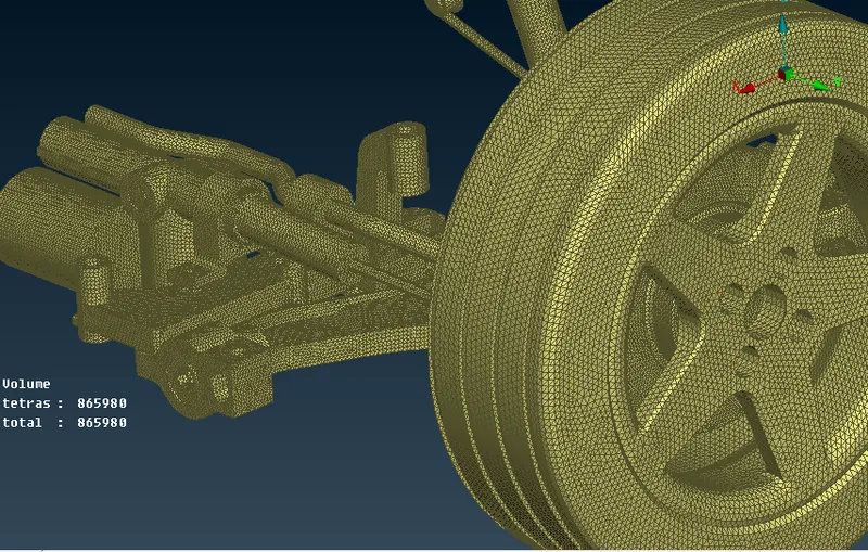
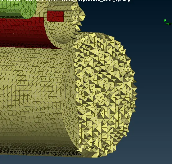
- For meshing the volumes, TETRA RAPID algorithm has been implemented, and the result is shown with respect to the given quality i.e TET COLLAPSE for 0.2.
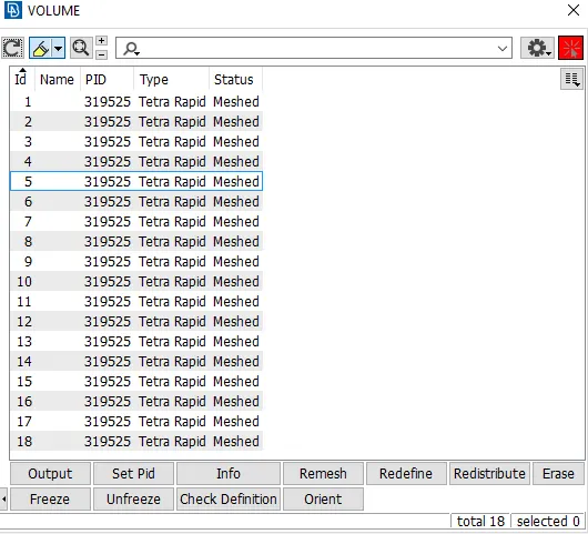
- The outcome for volume meshing can be seen as follows;
-
- CONNECTIONS :
- In the given assembly, we can see the different kind of connections requirement, majority of which falls in RIGID BODIES.
- RIGID BODIES : The connection acts as arigid body as all the DOFs are arrested given 123456. Some of them shown below;
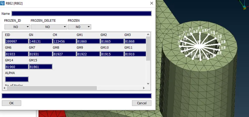
- In the above snap, the dialogue can be seen called RBE2 CARD, provides all the INFO, can be seen using ELEMENT > INFO in NASTRAN Deck.
- GM,GM2...GMn is called SLAVE NODES ID
- GN is called the MASTER NODE ID
- CM shows the DOFs arrested.
- RIGID BODY ELEMENTS ( BOLTED JOINTS ) : The joint is generally used to connect two different component rigidly with all the DOFs arrested. Shown below;
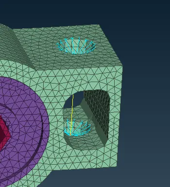
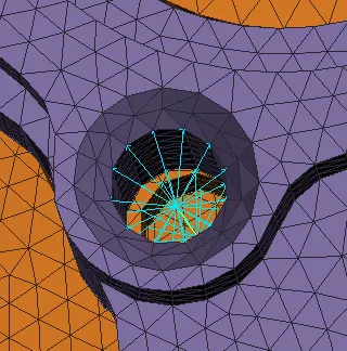
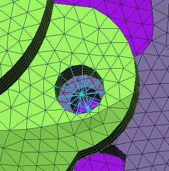
- The yellow line visible is the STEM LENGTH of the bolt.
- The above connection can be realized in two ways, either by creating a point using ONCOG and then convert it as bolted joint and then realize it or by using ELEMENTS > RBE2 > MANY NODES/TWO NODES. In the given order.
- SEAM WELDS : It is used to connect two combinations, for parallel faces OVERLAP SHELL and for perpendicular Y-JOINT SHELL. Here the situation is for PARALLEL CONNECTIONS.
- First we need to make a CURVE along the face using CONS2CURVE.
- Then convert the CURVE to SEAM LINE.
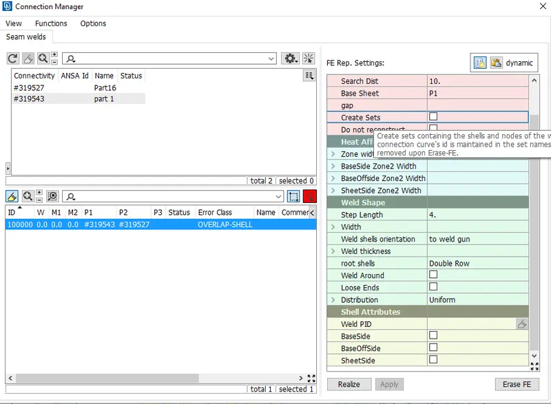
- This SEAM LINE is then realized in CONNECTION MANAGER, the P1 and P2 is to be chosen such that the thicker one assigned as P1.
- The FE Rep type chosen is OVERLAP SHELL as the connection is parallel.
- PID is to be created.
- some user defined data like SEARCH DISTANCE and element length has to be fed and then realized. As shown below;
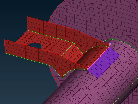
- The SEAM WELD realized is as follows;
- After all the operations, now one half of the assembly is to be MIRRORED to the other side symmetrically.
- SYMMETRY OPERATION :
- As the given assembly is one half, we need to mirror it exactly to the other side which is done by using the function TRANSFORM > COPY.
- After selecting the entities and on confirming with the middle mouse button, the following dialogue box appears;
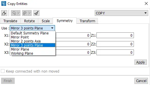
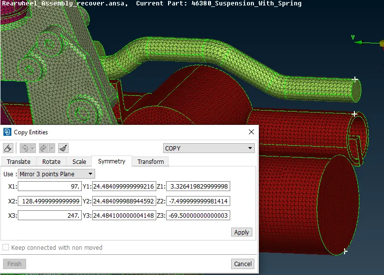
- The MIRROR 3 POINTS PLANE method has been deployed in order to mirror the half, and the 3 points has been selected in such a was shown below namely X1, X2 and X3;
The final result after copying all the entities and connection the final output came as shown below;
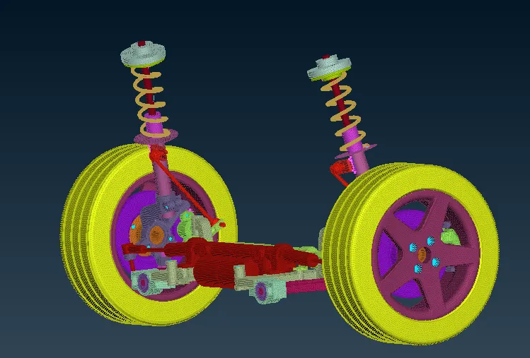
In the given REAR WHEEL ASSEMBLY model, we have encountered almost every operation that has been practised, in addition to it, comparision between operations and choosing the optimal for case dependent. The new thing we came across during this project is the conversion of SUSPENSION SPRING as a PBAR element. practised the mirroring of the one half to project on the other side.
CONCLUSION :
- The CAD of REAR WHEEL ASSEMBLY half has been imported and cleaned for any geometrical error post which the PIDs are assigned for all the subcomponents.
- MIDSURFACING is done for the component having thickness < 5mm and been surface meshed using MIXED ELEMENTS.
- NON UNIFORM THICKNESS components has also been surface meshed with different QUALITY and MESH PARAMETER.
- The SUSPENSION SPRING is represented as a PBAR element and all the necessary connections has been made wherever required.
- VOLUME is assigned and has been meshed using TETRA RAPID algorithm.
- At last thickness is provided to the components for which midsurfacing is done and then symmetry operation is performed for all the entities.
FOLLOW THIS LINK FOR THE MODEL https://drive.google.com/file/d/1aDr-awTMXPjoew6-X1iuBMA8t6cvRLpZ/view?usp=sharing