Project - 2 - Meshing on the suspension Assembly
Objective
For the given assembly
1. check for the geometrical errors and mesh with the given element Quality criteria.
2. Use tetra elements to model non-uniform thickness components.
3. Use Appropriate connections to connect the component.
4. Perform Symmetry command to reflect the half finished model to the other side.
Procedure
Geometry Cleanup
1. Import the geometry into ANSA by using the open option in the file menu.
2. Check the geometry by using Checks > Geometry in the tool menu.
Execute the check on each component to find the geometry errors
Try eliminating the errors by using the autocorrect options initially, if that does not eliminate all errors use manual operations like deletion, creation or fusing of surfaces to eliminate the error.
Meshing Component with Uniform Thickness.
We have to Midsurface two components that have uniform thickness.
1. Measure the thickness of the component.
2. Offset one side of the surfaces by distance equal to half the thickness to obtain the midsurface of each component.
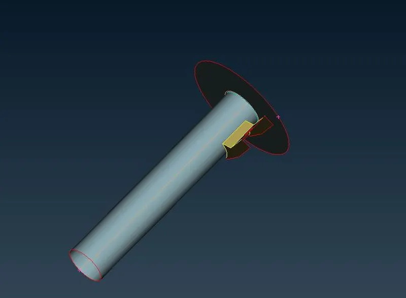
3. Set PID for each midsurface as mids1, mids 2 and so on and assign the corresponding thickness to each.
4. Use the “Best” option in the mesh generation menu to mesh the macros(with Mesh type as "Mixed")
5. Make sure the mesh elements follow quality criteria, use tools like reconstruct, split, paste etc to edit mesh in case any elements violate the criteria.
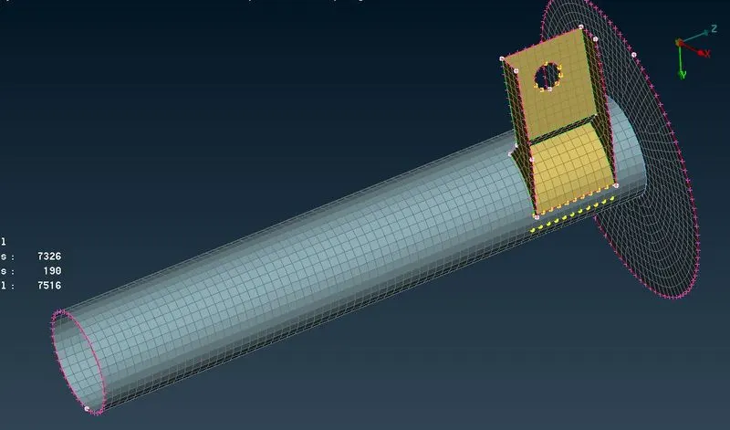
Components with Non Uniform Thickness.
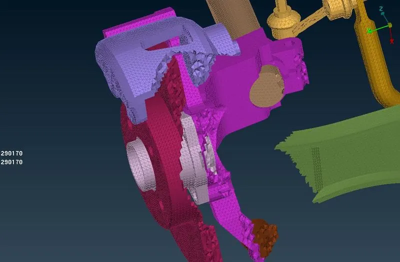
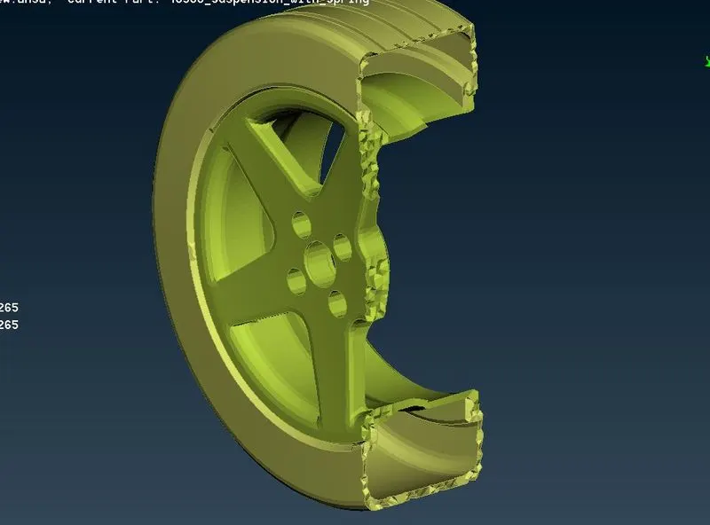
All Components with non uniform thickness need to be meshed with solid elements therefore we will create tria shell elements on the surface of these components and then use the surface mesh to generate the tetra mesh on the created volume.
1. Use the Length option under parameter menu to provide parameter and macro length to visulaise the model and refine the cad geometry.
2. Use the Spotmesh option in the mesh generation menu Mesh Curved macros with Ortho tria and flat macros by Trias.
3. Mesh all Non uniform parts of the geometry by the procedure in step 4. if some elements fail the quality criterion use reconstruct option in the Shell Mesh menu to reconstruct the mesh and eliminate the off elements.
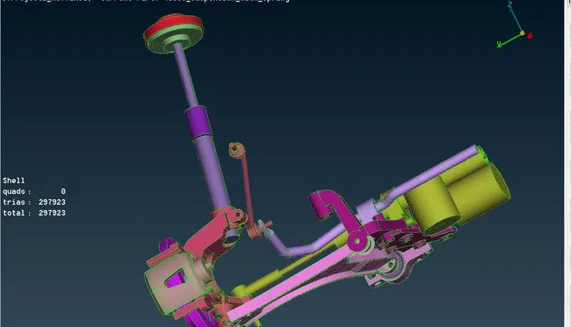
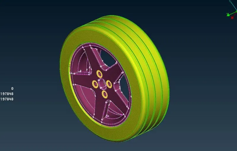
4. After Completing the Shell mesh on each part, Use the Define option under the Volume option in the Volume menu (Volume Mesh) to define volume for each part. Use manual selection to select the element used to define the volume.
5. Use the Tetra Rapid/ Tetra FEM option under the Unstructured Mesh menu and select the corresponding volume to generate the Tetra mesh.
Modelling Spring and Connections
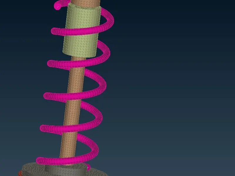
1. To Model the spring
- Generate a middle curve going through the centre of the spring's crossection using middle tool in the curves menu.
- Generate CBAR elements on the curve under the NASTRAN menu(element size as 4).
2. Bolt Connections
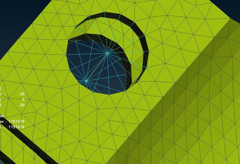
Bolt connection are deployed along concentric holes between the element.
One of the ways to generate bolt connection is
- Create a Multi node RBE2 connecting all the nodes on the periphery of the closed curve.
- join the mater nodes of the 2 Multi node RBE2 elements with a 2 node RBE2 element.
3. Seam Weld.
We need to connect the two components with shell elements using Seam weld
To deploy a seam weld connection
- Create a curve on the component where the seam weld starts and Convert the curve to Seam curve using the Convert option.
- Open Connection Manager and select P1 and P2
- Set FE Rep Type as OVERLAP-SHELL (for Parallel parts)
- Set appropriate search distance and root shells and realize the connection
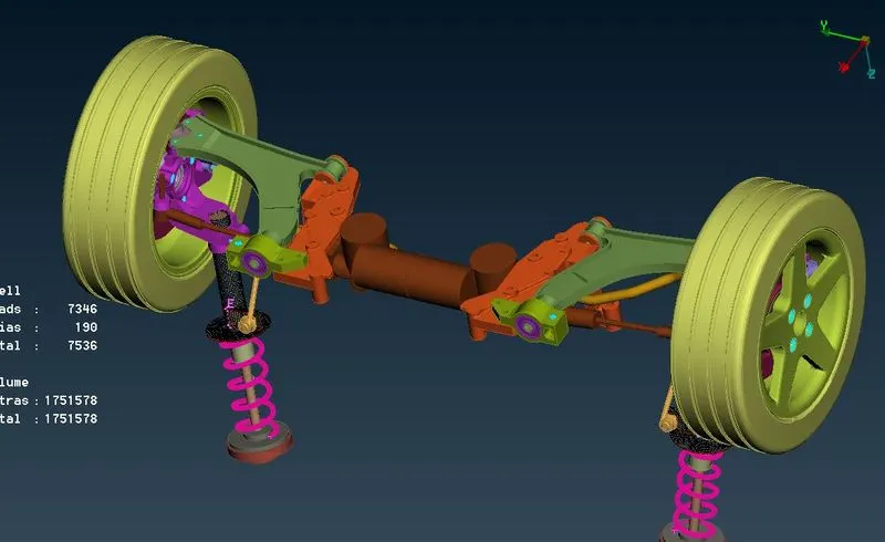
Reflect the half finished model
After Completing the half model we use the symmetry option under transformmenu to copy and reflect the model across a plane defined by 3 points
Learning Outcome
1. Geometry Cleanup of a large and complicated model.
2. Shell Meshing and Solid Meshing of many interconnected components
3. Deploying connection between Volume components.
Conclusion
The Model was meshed with shell and Solid mesh as required for different components, the meshed component was subsequently joined by using connection like Bolts and Welds, finally the half model was reflected to obtain the complete model.