Project - 2 - Meshing on the suspension Assembly
Aim:
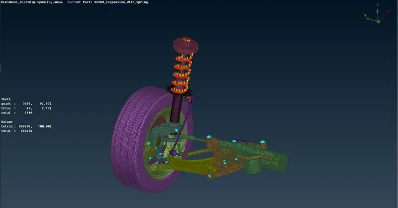
To generate mid surface for all the components with uniform thickness (under 5mm), tetra meshing for all the non-uniform thickness components and to assign appropriate connections to the components in the given Rear wheel suspension assembly model after verifying the geometrical errors and to satisfy the given Quality criteria.
Procedure:
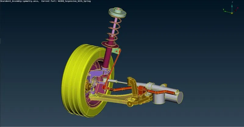
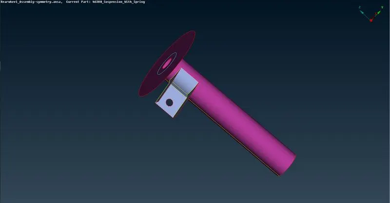
2D meshing can be done for the Strut base portion and the Strut clamp. All the other components are meshed with Tetra mesh.
Import Geometry:
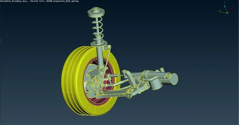
Go to File > Open > Select file to import
Topology clean-up:
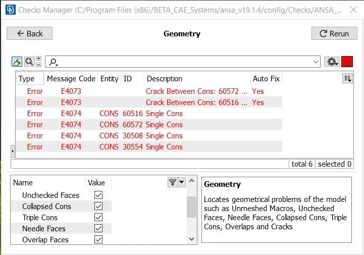
- Initially when the model is opened, perform Checks > Geometry on each and every component that are present in the model to make sure there are no irregularities present. If any errors occur, we can use Auto fix to solve them or do it manually by using various commands in the Topo deck.
- At times when some of the features are not appearing in their original form, the Auxiliaries > Fine command can be used to increase the resolution at that particular area and check the original shape of the feature.
- Then, the Faces > Orientation command is performed to make sure that all the faces are in same orientation (i.e., positive or negative).
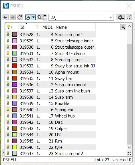
- Create individual PIDs for all the different components.
2D Meshing (Uniform Thickness components)
Mid-surfacing:
- To create the mid-surfaces, Faces > Offset command can be used.
- Faces > Intersect can be used to remove unwanted surfaces.
- The Faces> Topo command can be used to make sure that all the adjoining mid-surfaces are stitched together.
- After generating mid-surface for all the components, individual PIDs for the different components is created.
- Geometry check can be performed once again to eliminate any errors that are present.
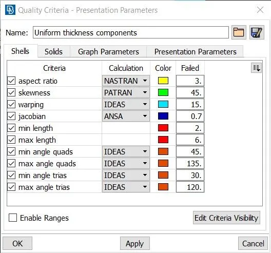
Define Quality Criteria - Shell:
Press F11 to open Quality criteria window. Then, Select and define the required criteria.
Meshing:
- Open Mesh parameters and enter appropriate values.
- For meshing the surfaces, Use Best Mesh algorithm from the Mesh generation panel.
- Always start meshing from the features.
- To view the mesh quality, Toggle Hidden mode.
- Use Shell mesh > Reconstruct to reform the mesh elements.
- Use Shell mesh > Smooth to smoothen the mesh element structures.
Some of the basic conditions to be kept in mind while meshing are as follows:
- No Tria elements should be present at the perimeter and the holes.
- No Tria elements should be connected back-to-back or present opposite to each other.
- No Tria elements should be on the features and fillets.
- Max no. of elements should be perpendicular to each other (Minimise wavy mesh flow patterns).
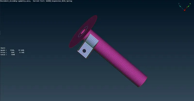
Volume Meshing (Non-Uniform Thickness components)
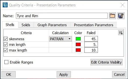
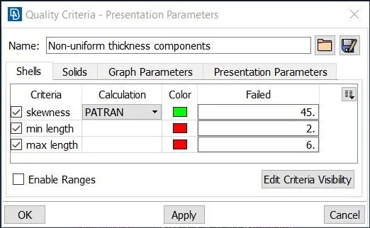
Define Quality Criteria - Shell:
Press F11 to open Quality criteria window. Then, Select and define the required criteria.
Meshing:
- Open Mesh parameters and enter appropriate values. Choose tri elements in the element type drop down menu.
- For meshing the surfaces, Use Spot Mesh algorithm from the Mesh generation panel.
- Always start meshing from the curved features.
- To view the mesh quality, Toggle Hidden mode.
- Use Shell mesh > Reconstruct to reform the mesh elements.
Volume Creation:
- After completing the 2d meshing of the outer surfaces of the components, goto Volume Mesh deck.
- Goto Define > Manual and select each of the different components to create a volume out of it which is needed to create 3d mesh elements.
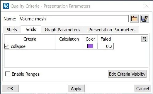
Define Quality Criteria - Solid:
Press F11 to open Quality criteria window. Then, Select and define the required criteria.
Tetra Meshing:
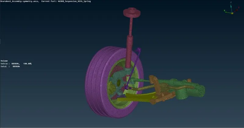
After creating the volumes for different components, we can use either Tetra Rapid or Tetra FEM algorithms in order to generate unstructured Tetra elements.
Deploying Connections
In this model I have used the following types of connections.
- RBE2 cluster
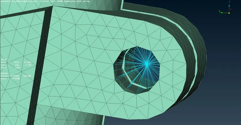
- Goto Nastran deck > RBE2 > Many Nodes and select the nodes where RBE2 connection needs to be established.
- Click Next > Next > Finish.
- RBE2 with 2 Node RBE2
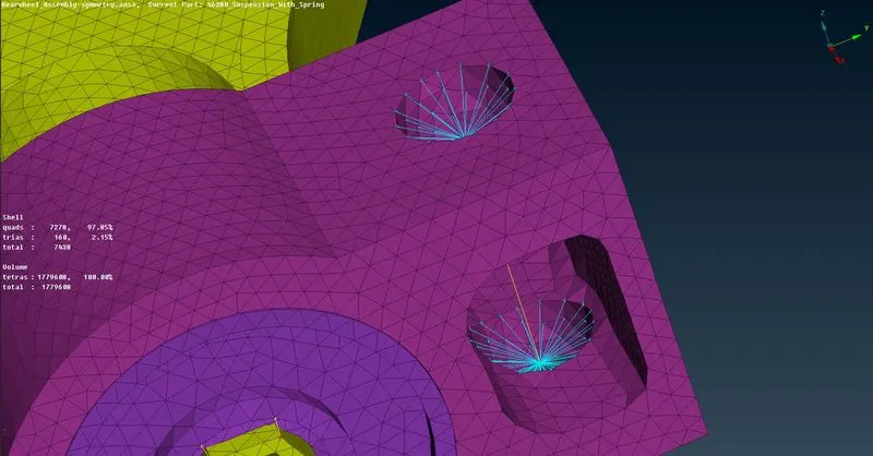
- Goto Nastran deck > RBE2 > Two Nodes and select the nodes where 2 node RBE2 connection needs to be established.
- Then, Middle mouse Click > Enter name > Enter the degree of freedom and click on OK.
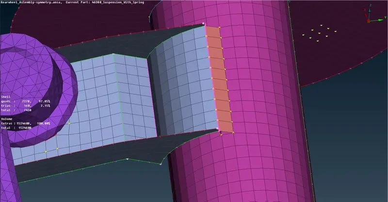
- Seam Weld
- Select the edges where seam weld connections need to be established and convert it into curves using the Feature2curve option.
- Then Goto Convert > Curves > Seam line to convert the curve into Seam line
- Open connection manager and select the seam line and middle click on the mouse. Then select P1 and P2.
- Select OVERLAP-SHELL in the FE rep type drop down menu.
- Enter all the required parameters and click on Apply and then Realize to deploy the connection.
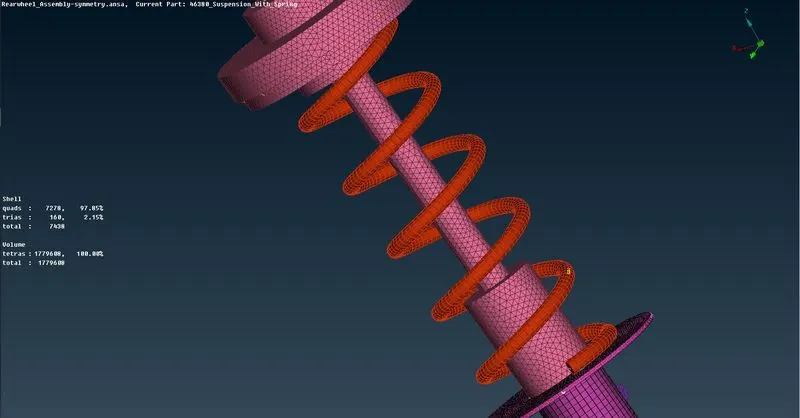
- PBAR (Spring coil)
- Create a middle curve by using the Curve > Middle option.
- Connect the curve into a single curve by using the Connect > Multi option.
- Now create a cog point for the curve to define the orientation of the elements.
- Goto Nastran deck > CBAR > Curve Box > Select the curve and select the point for orientation.
- Enter the element length.
- Create a new PID and define the radius of the spring in order to calculate the cross-sectional area and the moment of inertia.
Symmetry operation
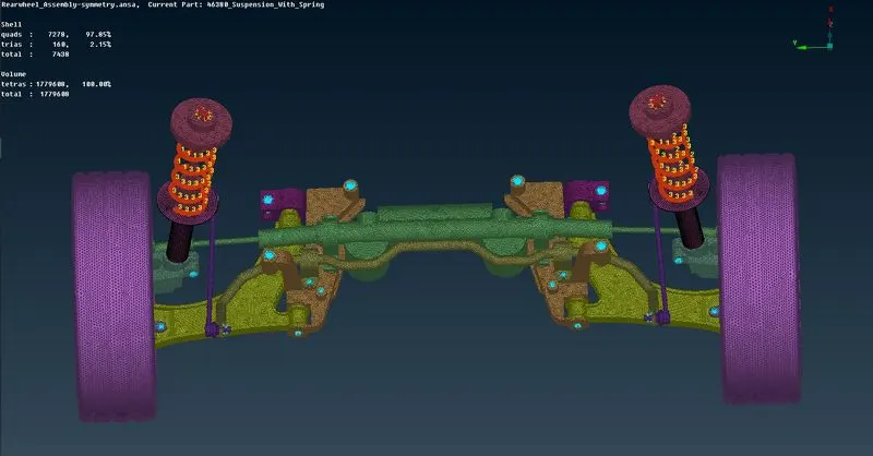
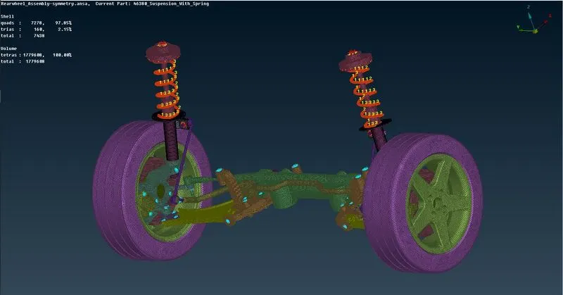
After completing all the necessary meshing and connection operations, we can do the symmetry operation to mirror the quarter car model to the other side.
Goto > Transform > Copy > Symmetry > Mirror 3 points plane to do the symmetry operation.
Learning Outcomes:
- Gained better fluency with the ANSA GUI.
- Acquired aptitude on identifying and improving failing and bad quality elements.
- Learnt to use the different midsurfacing and meshing techniques.
- Gained fluuency in fixing tet collapse off elements.
- Gained knowledge on the different types of connections available and the various approaches to assign the connections.
Conclusion:
Thus, Generation of mid surface for all the components with uniform thickness (under 5mm), tetra meshing for all the non-uniform thickness components and assigning appropriate connections to the components in the given Rear wheel suspension assembly model after verifying the geometrical errors and satisfying the given Quality criteria is completed.