Project - 2 - Meshing on the suspension Assembly
ANSA Project 2:
For the given assembly, check for the geometrical errors and mesh with the given element Quality criteria. After meshing the component the thickness has to be assigned for mid surfaces. Use tetra elements to model non-uniform thickness components. Also use Appropriate connections to connect the component as suggested in the Project-2 video (Use PBAR elements to model suspension spring). At last perform Symmetry command to reflect the half finished model to the other side.
Write a detailed report on your meshing process and also mention which method you used to extract the mid-surface along with the reason.
Common Note:
- Use Volume mesh for Tyre and Rim with below Quality criteria. (Use Tria Element)
- Use mid surface only when the thickness is uniform and less than 5 mm. (Use Mixed elements)
Quality Criteria for Surface Meshing of Tyre and Rim (Element type: Tria) :
|
S.No |
Quality Criteria |
Value |
|
1 |
Target/Average length |
6.5 |
|
2 |
Minimum Length |
5 |
|
3 |
Maximum Length |
10 |
|
4 |
Skewness |
45 |
Quality criteria for Surface Meshing of Non Uniform thickness components other than Tyre and Rim (Element type: Tria) :
|
S.No |
Quality Criteria |
Value |
|
1 |
Target/Average length |
4 |
|
2 |
Minimum Length |
2 |
|
3 |
Maximum Length |
6 |
|
4 |
Skewness |
45 |
Quality Criteria for Volume meshing of all Non Uniform thickness components (Element type: Tetra Elements):
|
S.No |
Quality Criteria |
Value |
|
1 |
Tet-collapse |
0.2 |
Quality criteria for Mid surfacing of Uniform thickness part which has thickness less than 5 mm (Element type: Mixed elements) :
|
S.No |
Quality Criteria |
Value |
|
1 |
Target/Average length |
4 |
|
2 |
Minimum Length |
2 |
|
3 |
Maximum Length |
6 |
|
4 |
Aspect |
3 |
|
5 |
Warpage |
15 |
|
6 |
Skewness |
45 |
|
7 |
Jacobian |
0.7 |
|
8 |
Minimum Quad Angle |
45 |
|
9 |
Maximum Quad Angle |
135 |
|
10 |
Minimum Tria Angle |
30 |
|
11 |
Maximum Tria Angle |
120 |
Procedure:
- Geometry Cleanup:
- Import the Rear Suspension Assembly file in ANSA Preprocessor.
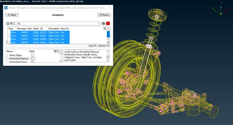
- Do Topo & make geometry check for errors and correct it using auto/manual techniques.
- After geometry cleanup.
2. Midsurfacing :
- Before Midsurfacing. Make each part as a different PID.
- For that Select the individual parts using PID Region option and use Faces>Set PID>New in Topo module.
- Name each part individually unique so that there is no confusion.
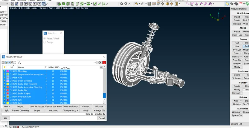
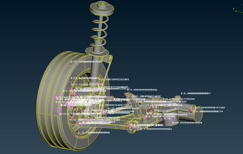
- After creating PIDs, measure individual parts thickness.
- Here the parts with uniform thickness througout (<5mm) will be 2D meshed after midsurfacing and remaining ones with non-uniform thickness will undergo Volumetric meshing.
- Now first of all uniform thickness parts needs to be midsurfaced. By selecting individual part to be midsurfaced use auto or manual midsurfacing techniques.
- Here I have used manual midsurfacing. By using Faces>Offset command in topo module after getting thickness data.
- After creating midsurface, assign thickness of midsurfaced part. Use Faces>Set PID.
3. 2D Meshing :
- After midsurfacing all the uniform thickness parts, Select all the midsurfaced part to show only.
- Set the Quality parameters as per requirements shown below:
- Quality criteria for Mid surfacing of Uniform thickness part which has thickness less than 5 mm (Element type: Mixed elements) :
S.No
Quality Criteria
Value
1
Target/Average length
4
2
Minimum Length
2
3
Maximum Length
6
4
Aspect
3
5
Warpage
15
6
Skewness
45
7
Jacobian
0.7
8
Minimum Quad Angle
45
9
Maximum Quad Angle
135
10
Minimum Tria Angle
30
11
Maximum Tria Angle
120
-
Now go to 2D Mesh module and use command Mesh Generation>Batch>Visible.
-
Ansa will automatically form 2D mesh for selected parts.
-
After meshing is done. Check for Mesh quality using Check manager.
- If any uncertain points or off elements shown. Then solve it using auto fix option and for remaining solve it using manual methods like moving elements, removing coons for smaller areas and features.
- Now set the quality parameters for Tyre & Rims seperately after selecting those & showing those parts as per requirements shown below:
-
Quality Criteria for Surface Meshing of Tyre and Rim (Element type: Tria) :
S.No
Quality Criteria
Value
1
Target/Average length
6.5
2
Minimum Length
5
3
Maximum Length
10
4
Skewness
45
- Now use Mesh Generation>Batch>Visible. This will do 2D Mesh to all these parts which are visible.
- If any uncertain points or off elements shown. Then solve it using auto fix option and for remaining solve it using manual methods like moving elements, removing coons for smaller areas and features.
4. Volumetric Meshing:
- After Meshing of all Parts we will proceed to assigning volume to each set of closed shell elements (for Volumetric Meshing).
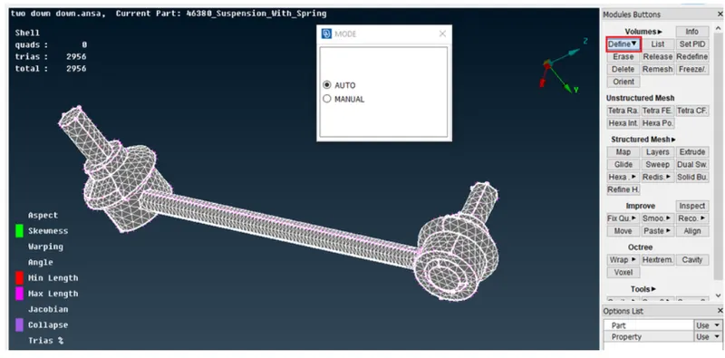
- Use Volume>Define>Manual and then select the region having volume. Auto automatically detects & defines selected closed volume, whereas manual option lets us define properties for volume that is to be defined. Either method works here.
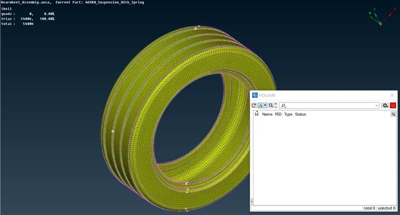
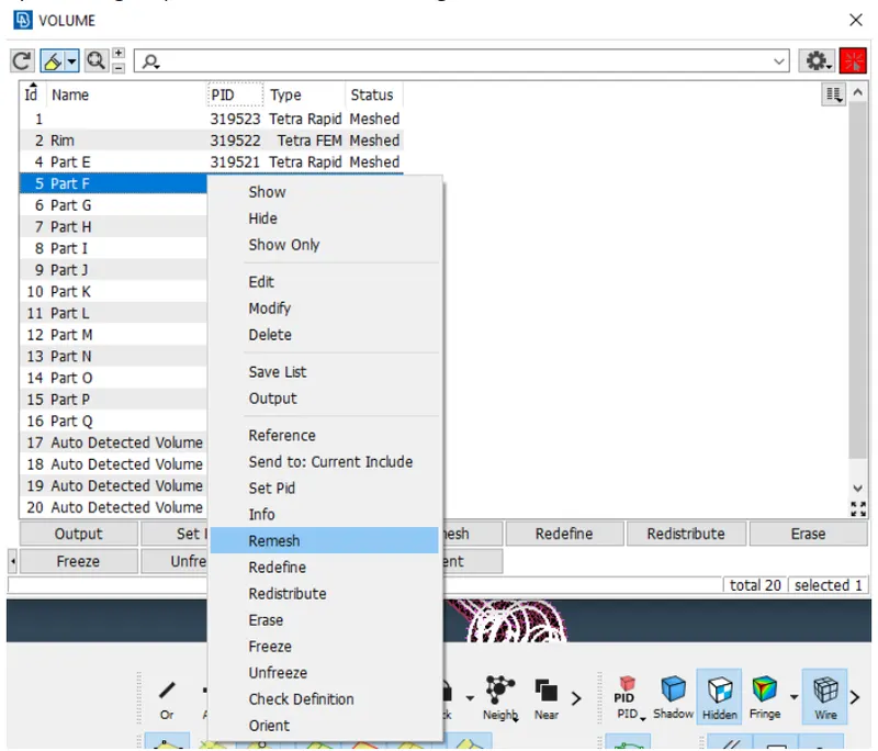
- After Volume is defined, the list of defined volume can be accessed by Volumes>List. The volumes that are unmeshed can be 3d Meshed by right click>Remesh.
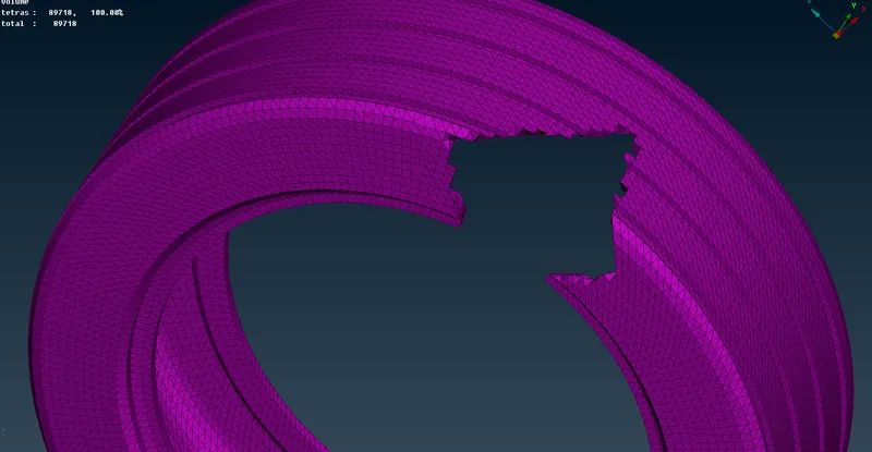
- We will get the Volumetric Meshed model, the tyre is shown in below image:
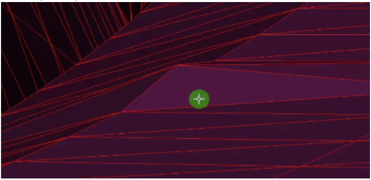
- Now we have to check if the formed solid body is having any defects for tet collapse criteria. This we can do by entering the value of tet collapse quality criteria in quality manager tab.
- After that switch to hidden mode and check for any tet collapse or extruding surface.
- To fix tet collapse failure we can use two methods :
- Use Check Manger>Quality after wards it will show the failing elements, select those points and give right click>fix. ANSA will fix these errors automatically. But after fixing some areas will get protrusions.
- Another way is to use MV Free tool using Grid>MV Free in mesh module. Using this we can manually arrange the height of protruding elements by dragging after selecting particular node.
- 5. Meshing the Suspension Spring Component:
- For Spring component the 1D CBAR element representation is required.
- First generate a middle curve that runs throughout the spring cross section using Curves>Middle of topo module.
- Here during this operation we have to select the coons opposite to each other going throughout the spring cross section.
- After wards connect all the broken curves using Curves>Connect>Multi Tool.
- Then define a COG point for the curve generated from the spring using Points>On C.O.G. command.(Take diameter to be 10mm as per measurement).
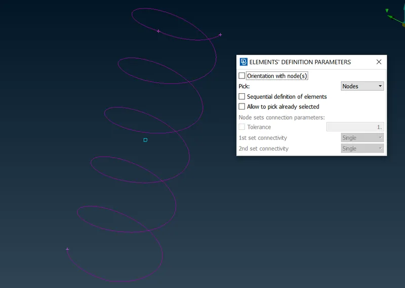
- Now going to NASTRAN module use Elements>CBAR. In the popup check 'orientation with nodes' and select 'Curve (box)'. Afterwards click the middle mouse click.
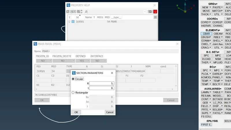
- After middle mouse click a popup will apprear where a new PID needs to be created.
- In next window, input area (A) using Shift+? to open another window where cross sectional radius of spring needs to be specified.
- Then the algorithm will automatically calculate & feed the other values on the PID Card as per given radius.
- On Proceeding we get the 1D Elements for spring.
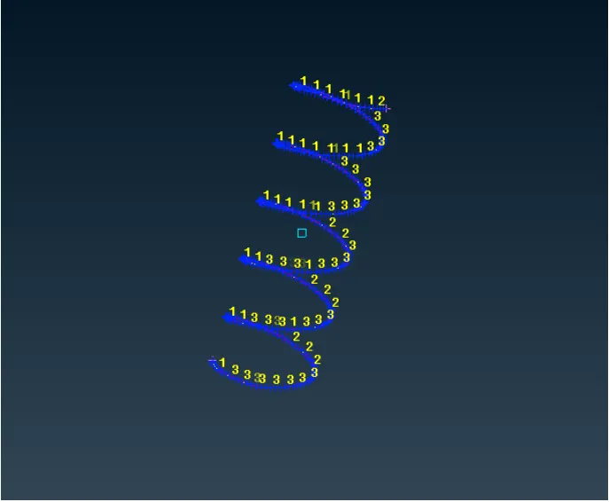
- To represent this in 3D solid go to Quality criteria window & check the 'Lines Elements Cross Section' box & Select 'as solids'.
6. Assigning Connections:
- After ensuring all the parts to be meshed we can proceed for the connections for the assembly.
- For Bolt connected regions we use Two Node RBE2 option. Elements>RBE2 in NASTRAN deck.
- First for RBE2 components for individual nodes will be created using Elements>RBE2>Many Nodes option. Now select the nodes surrounding the hole.
- After creating these components for individual holes use Elements>RBE2>Two Nodes and select the two master nodes created and middle click. This will create the representation for stem of the bolt.
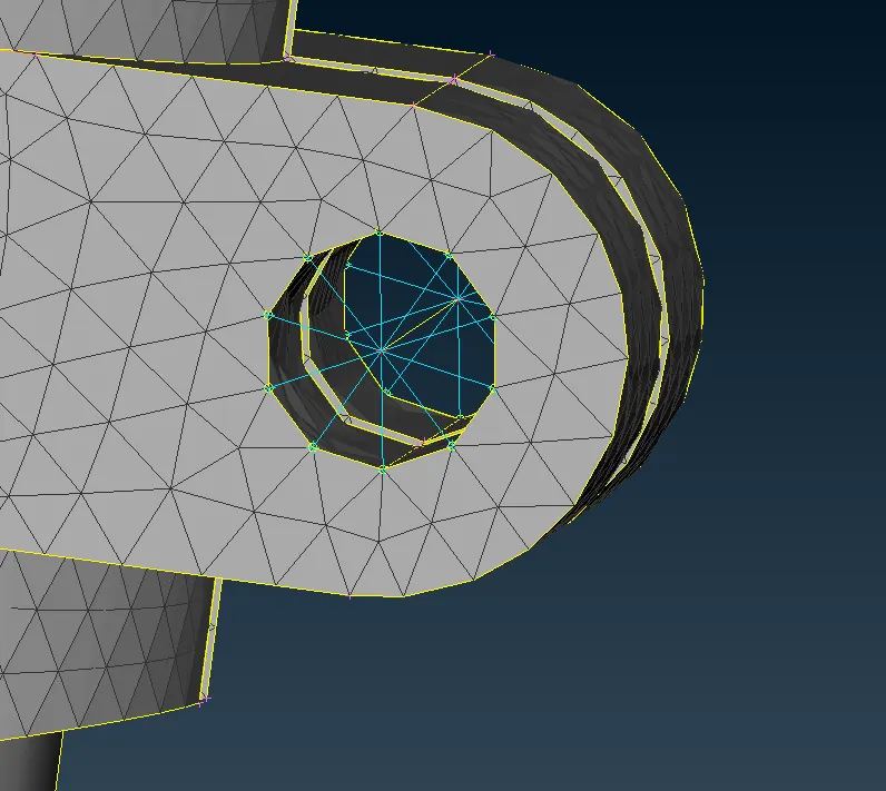
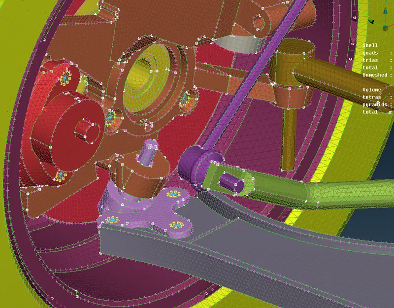
- Second the cylindrical parts going through holes need to be represented as connection. Here simple RBE2 Connection will be shown but in different way.
- Here we will create connections between two nodes of different elements.
- For this we have to use Elements>RBE2>Two Nodes and we will be picking nodes to be connected as shown:
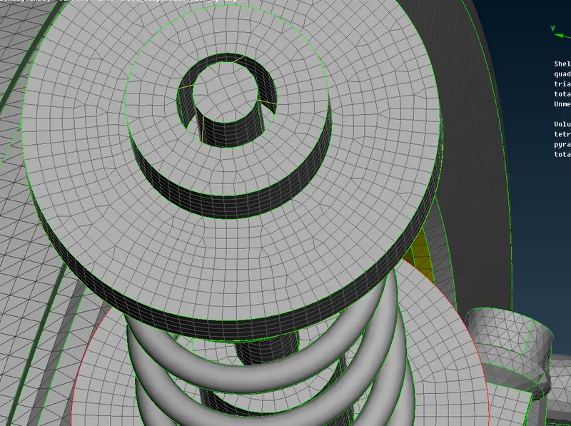
- Atleast 4 such connections for each location should be shown.
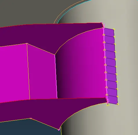
- Afterwards Seam weld connections will be represented. For this curve is created at the seam weld area using Curves>Cons2Curve option in topo module. Select the edge & derive the curve from it.
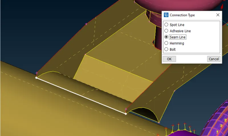
- Now using connection manager, Select the seam line & proceed where window will appear here all the required set of information for the connection will be provided as shown:
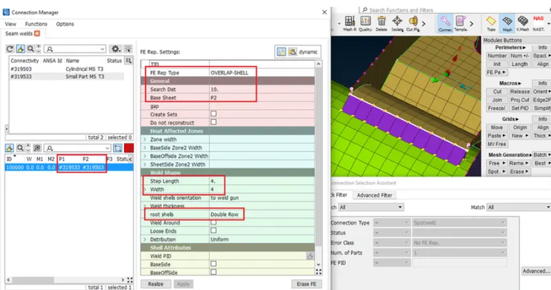
- Here we are using OVERLAP-SHELL in FE Rep type as the seam line is parellel to the surface. If it were perpendicular we would use Y-Joint Shell.
- Then we get this result as shown below:
- Lastly for deploying connections of spring part with neighbouring element we use cluster RBE2 elements.
- Use Elements>RBE2 in NASTRAN deck and select many nodes to select the parent set of nodes on spring and other set on other surface.
- Then middle click, it will create a master node and form connection as shown below:

7. Mirroring the Assembly:
- Once we have meshed the whole assembly & deployed all connections, we will proceed to mirroring of the assembly.
- For that use 'Transform' from toolbar. Select 'Copy'.
- Select the whole assembly which needs to be mirrored. Use show all and then select so nothing gets left out.
- Once 'copy' window is open. Go to Symmetry tab and select the 'Mirror 3 points plane' from drop down menu.
- Then select the three points at the edge plane of the assembly. On giving middle click twice and click on finish.
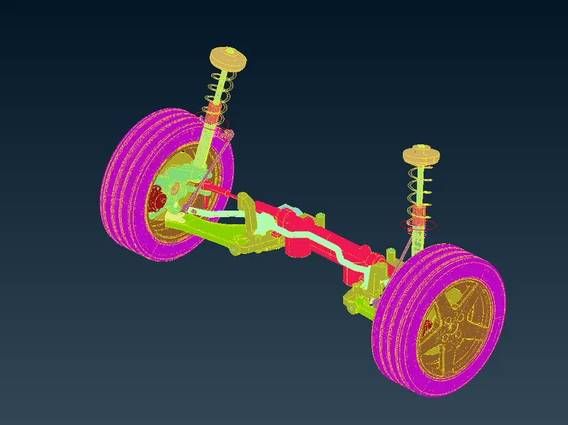
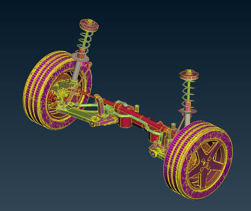
- Then we will get the final model as shown:
Conclusion :
1. Through this work, the tetra meshing & connection deployment process is cleared and understood well.
2. Learnt to use 1D CBAR element for spring component representation.
3. Learnt different parts available in suspension assembly.