Project - 2 - Meshing on the suspension Assembly
AIM:
The project aims to mesh the Front-wheel suspension assembly with 2D elements on the surface of the geometry and the volume inside the assembly is meshed with tetra elements. The mesh should have a good flow of elements and match the quality criteria and mesh parameters. Furthermore, the necessary connections have to be provided. The Mid-surface is taken for the part which has a thickness of below 5mm.
Procedure:
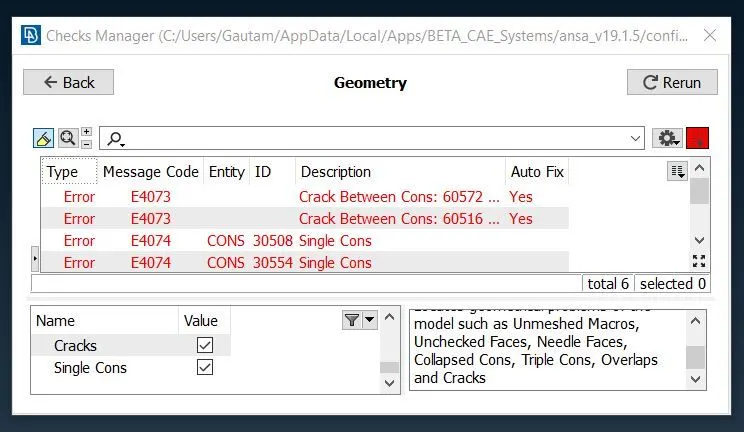
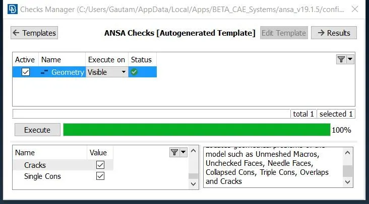
Once the model is imported in Ansa, the model is subjected to various checks to clean up the geometry. Under geometry check, 6 errors have been popped up, the single con errors are cleared by using the topo command and by selecting the whole surface of the component. The single cons are then converted into double cons whereas eliminating the single con errors and the other errors are cleared by using the auto-fix option. since the geometry topo is cleaned up, the material has to be defined in the material card. Orientation is done to get the same grey color all over the surface. The following figure shows that the geometry has been cleaned up.
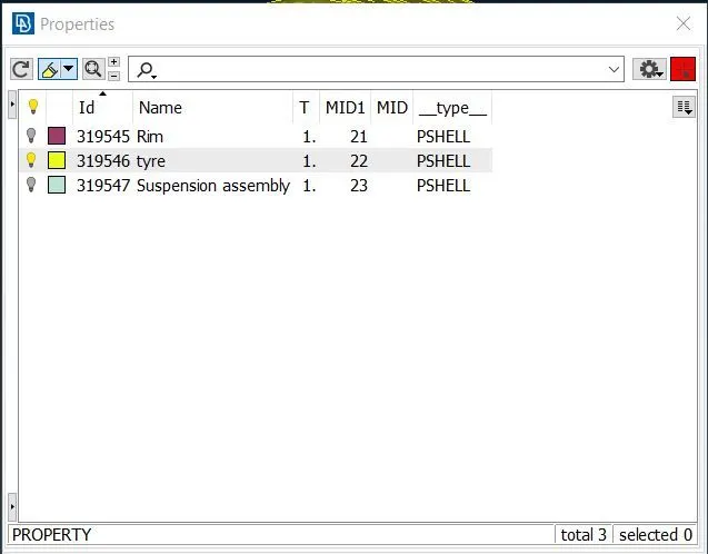
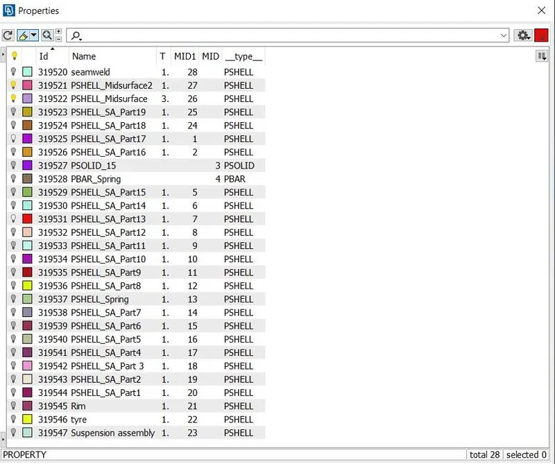
As it has been clear from the property card, the Front-wheel suspension assembly has properties for tyre, rim, and suspension shown in the figure.
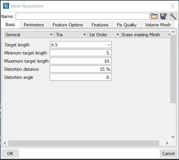
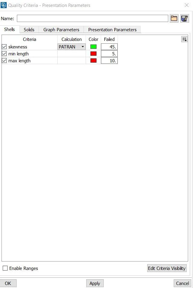
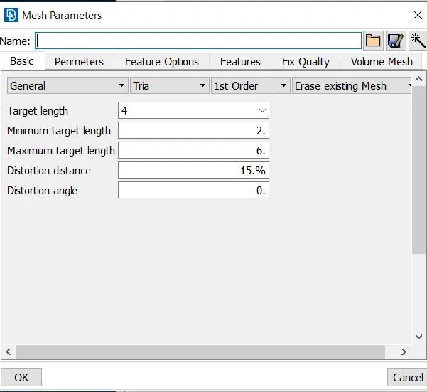
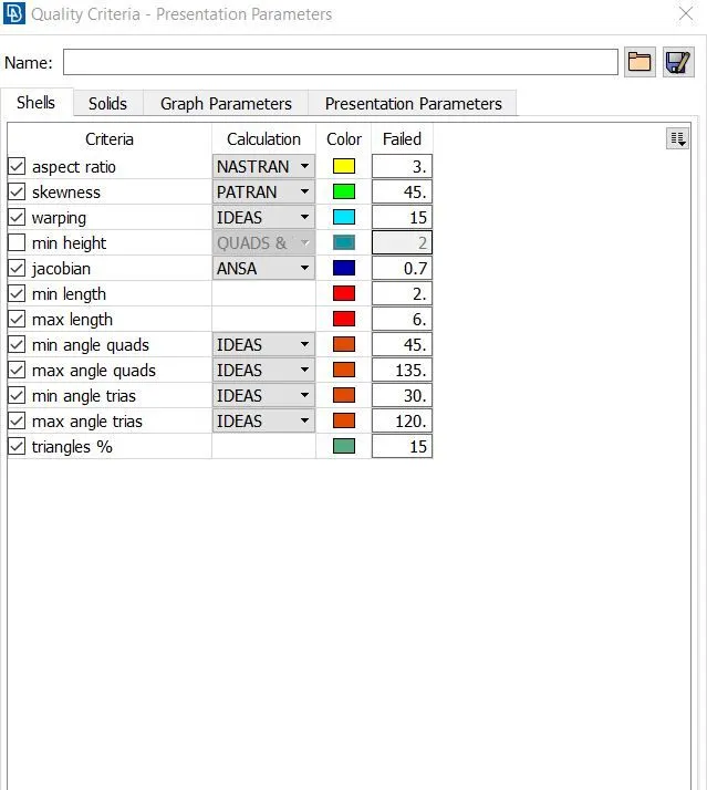
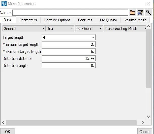
The thickness of the tyre and rim has been measured in the different faces. The Measured thickness is more than 5mm and non-uniform all over the surfaces. Since the thickness is more than 5mm and non-uniform all over the surface, the volume mesh generation should be carried out. To generate the volume mesh, there is no need to take a mid-surface for each different face. The mesh has to be carried out on the surface of the geometry. In the material card, the first property is chosen. The Mesh parameters and quality criteria have been set up according to the given condition. To generate the tria elements length of the element is considered such as Target length, Maximum Length, Minimum Length shown in the figure.
TYRE:
In mesh parameters, the element type is set as tria. The tria elements are generated on the flat surface of the geometry. In case for the geometry which has a curvy shaped portion or bend, the orthogonal elements are preferred to get a quality mesh on those surfaces. But considering the given quality parameters to avoid the maximum length quality failures, the element type is chosen as tria all over the surfaces. The target length is 6.5mm and the maximum length is 10mm is given and shown in the figure.
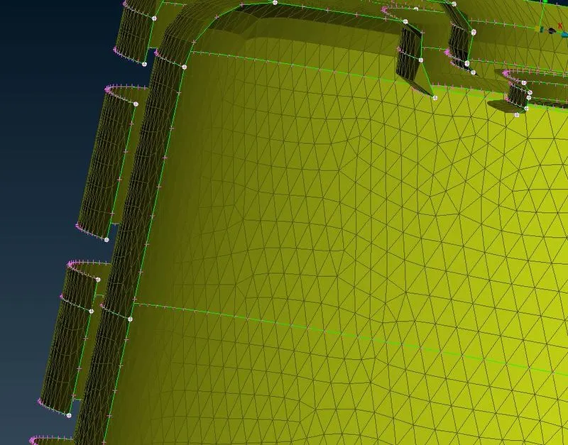
since the opposite and adjacent side of the tria is 6.5mm, the hypotenuse side becomes 13mm and fails for the max length criteria. Before meshing, the perimeter and macros edges should have the given element of 6.5mm. The distance between the nodes has to be checked at critical surfaces to avoid quality failures. If the distance between the nodes falls below the minimum length the defeaturing of the surface should be done. when the mesh is generated and it falls for minimum length by using the edge2perimeter option, the new con is generated, and joining the cons helps to avoid the quality failure at the critical points like fillets and curvy areas. once the mesh is generated, it is reconstructed to get a good flow of elements. As soon as the mesh has been generated, shadow mode should be shifted to hidden mode. In hidden mode the falling elements are visible for different qualities and care should be taken to avoid the off elements. All the off elements on the different parts should be cleared and each part should have good mesh flow and patterns. The same procedure is followed for the other parts to generate the mesh on the surface of the geometry.
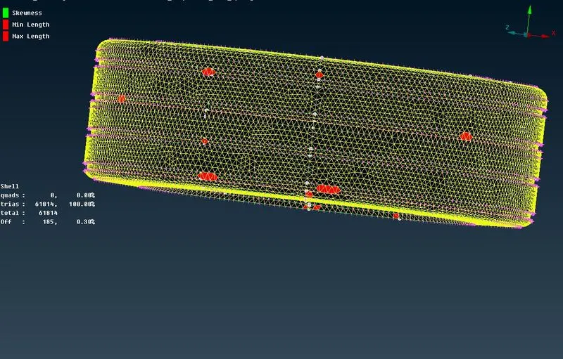
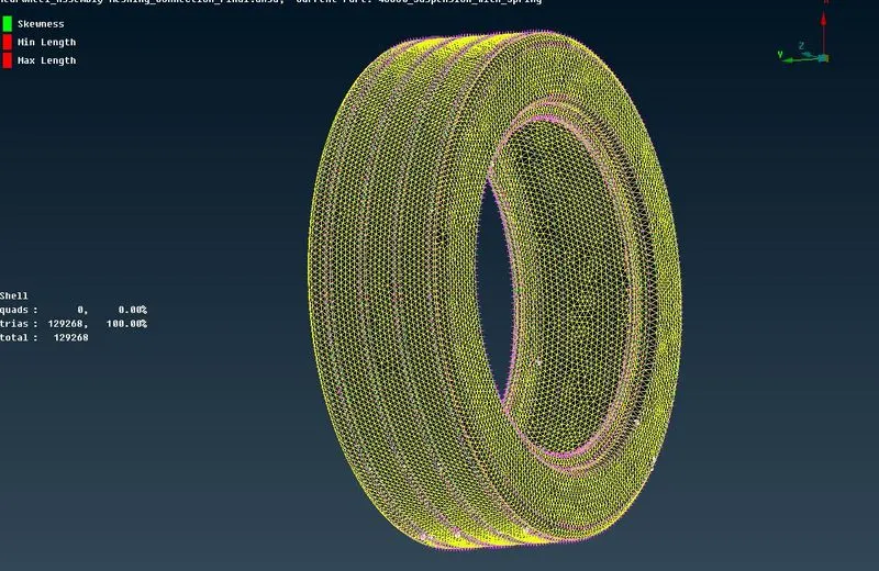
Since the 2D elements are generated, it is important to generate the volume mesh inside the volume of each component. To create a volume mesh, each part should have a closed volume. It should be checked before going into the next stage of the process. Moving on to the next step, Volume should be defined for each part. To define the volume, by using the define command in the volume mesh deck, the volume of the part can be defined manually. once the volume is defined, the same process has to be carried out for the parts. The defined volume can be checked by using the list command on the volume mesh deck.
once the volume is defined for each part, the list table shows the type of mesh and status as undefined and unmeshed respectively. To mesh the volume, either Tetra Rapid or Tetra FEM is used. In this project, the Tetra FEM command is selected to mesh the volume in each part.
Once the volume mesh is generated, the mesh has to be checked for tet collapse quality parameters. The quality failures are eliminated in the volume mesh and it has zero off elements. Surface quality after volume mesh is good and it has no kinks and dips. the following image shows that both 2D elements and volume mesh elements have zero off elements.
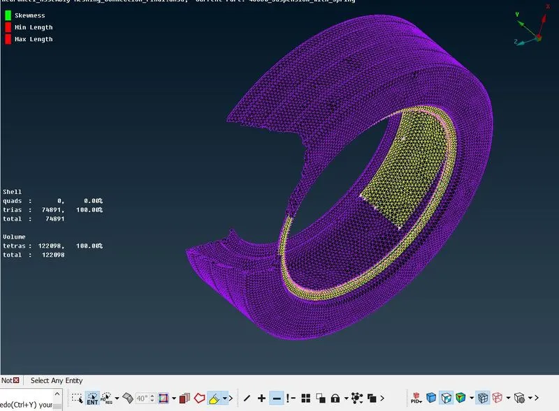
The above pictures represent the volume mesh that has been generated.
RIM:
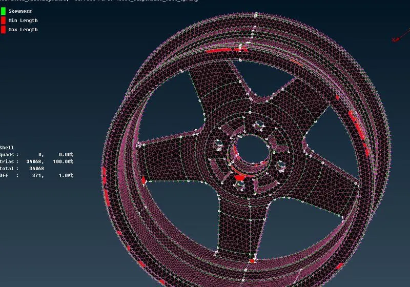
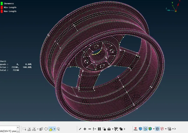
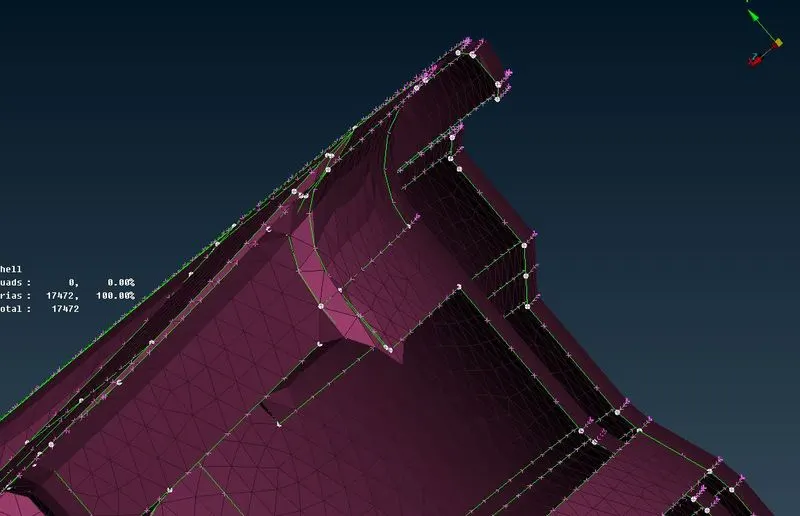
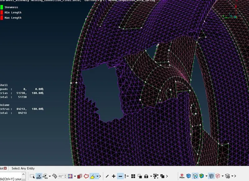
Once the volume mesh generation is completely done on the tyre, the second part rim is opened by the property manager. The same quality and mesh parameters have been chosen as per the given condition. Since it has a non-uniform thickness and the thickness of more than 5mm, the volume mesh generation has to be carried out. The above same procedure is followed for the mesh generation and for clearing the off elements which are used in the tyre part. The following images show the 2D mesh on the surface of the rim, volume mesh inside the rim, and zero off elements.
Suspension Assembly:
Once the volume mesh generation is completely done on the rim part, the third part suspension assembly is opened by the property manager. The suspension assembly part has many different sub-sections. To get a clear idea and to ensure good quality mesh generation, different PIDS are set up for the different sub-sections.
The thickness of the sub-section suspension part is measured at different faces. The measured thickness shows that one sub-section suspension part has a uniform thickness and a thickness of less than 5mm. As the thickness measured is 3mm, shell mesh generation has to be carried out. To proceed with shell mesh generation, the mid-surface is taken for the particular part by using the offset command. The mesh and quality parameters are defined as per the given condition and the element type is changed to mixed. The off elements are cleared and proper mesh floe is ensured on the generated mid-surface.
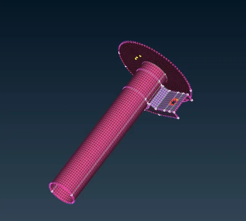
In the suspension assembly part, a spring element is provided. A solid spring always had to be represented in the 1D CBAR Element. To generate a 1D bar element, a curve is generated in the middle of the spring by using the middle command. The multi-curve is converted into a single curve by using connect multi command. The COG point is created to define the Orientation. Under the Nastran deck, by using the CBAR command the curve is selected and the orientation and length of the element are defined. The new PID has to be created to generate a 1D element. Under the new PID, the radius of the spring has to be defined and ANSA itself calculates the other necessary information to generate the 1D element. In Presentation parameters, the line element cross-section is chosen as solids to visualize the generated 1D element as a 3D solids.
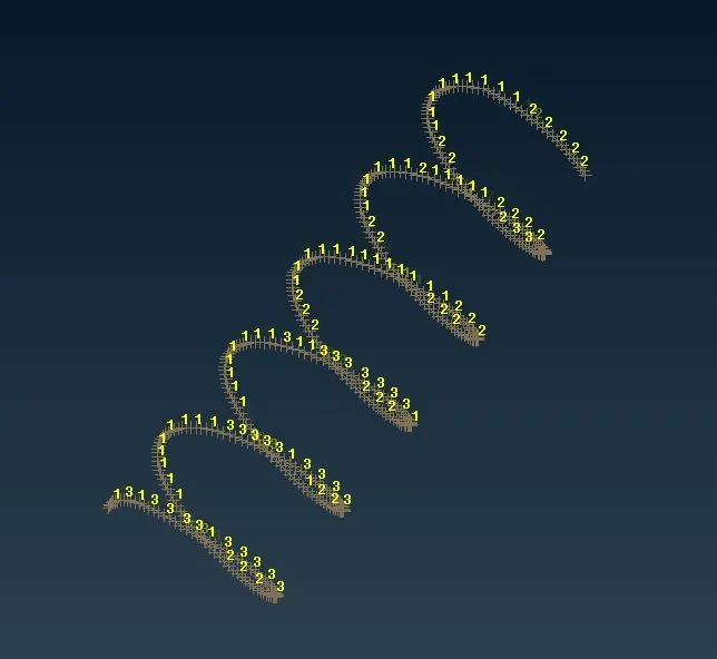
For the other sub-section suspension systems, to generate the volume mesh the procedure followed in the tyre and rim part is used.
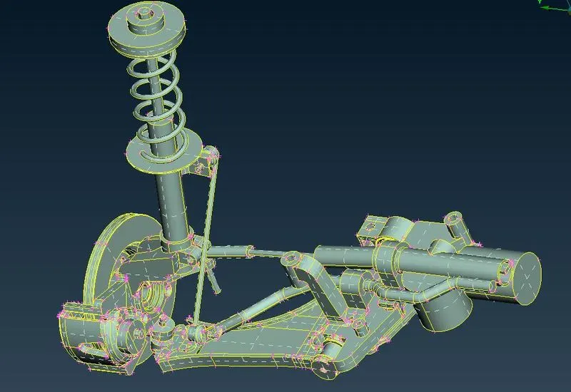
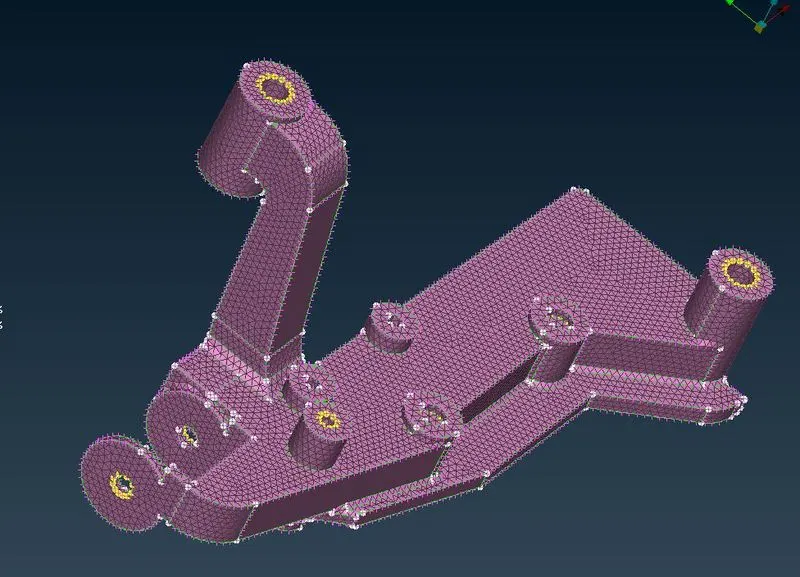
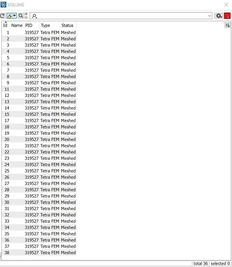
The picture shows that sub-section parts are separated from the main assembly and meshed individually. The volume has been defined for single sub sections and volume mesh has been generated according to the given parameters. The quality and mesh parameters Are different from the rim and tyre parts. The given quality and mesh parameters are defined. The off elements in the shell and solids are eliminated and the proper mesh flow is ensured.
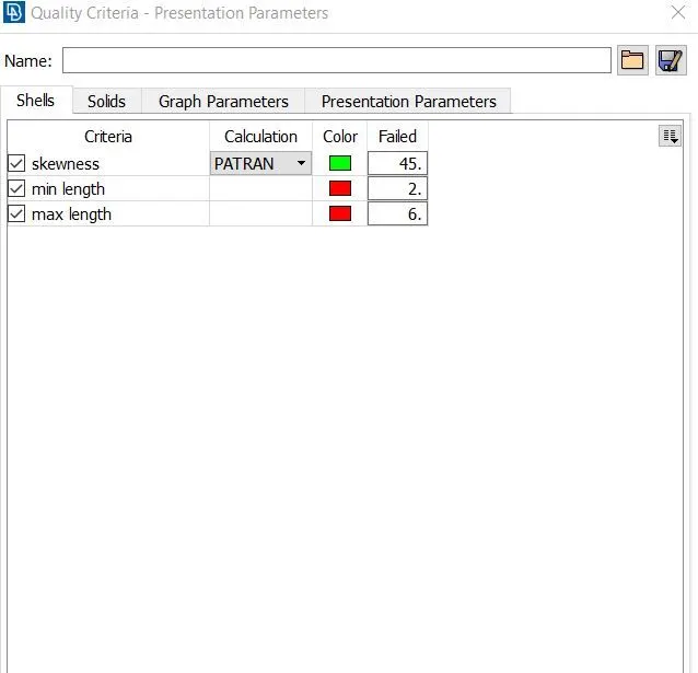
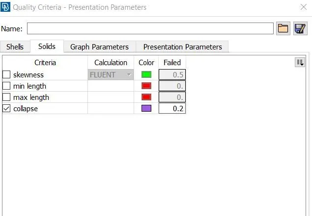
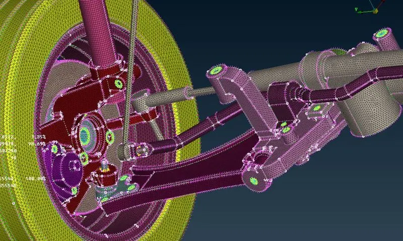
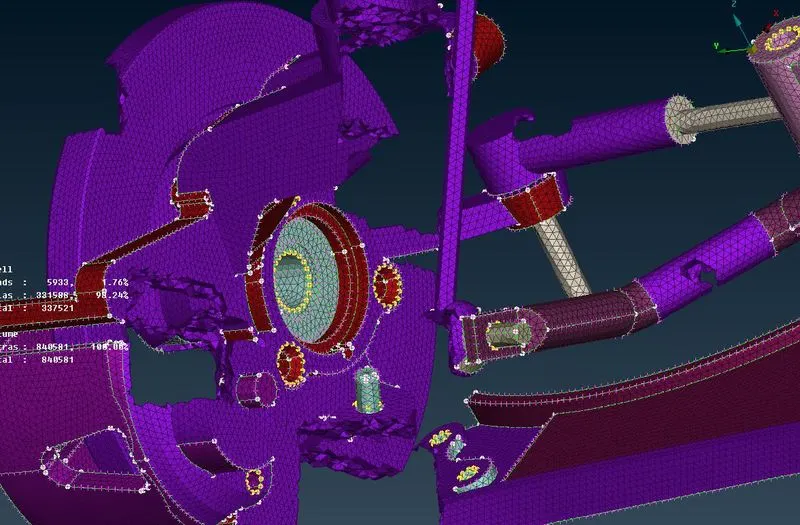
The penetration error occurs when the meshing of two nearby sub-section suspension assembly parts and care should be given to mesh each part individually. The following figure shows 2D and 3D elements on the suspension assembly.
Connections:
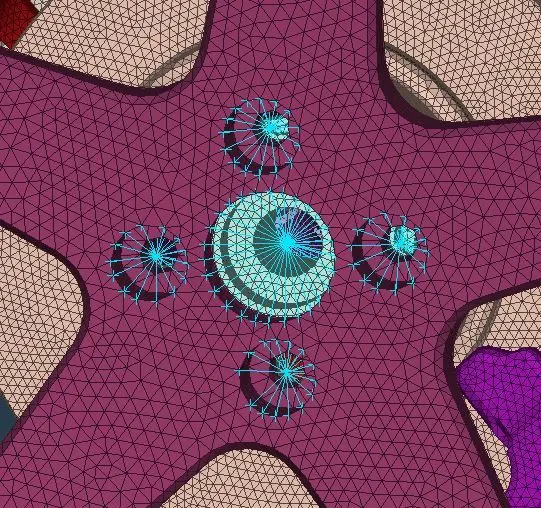
Once the mesh generation is completed, the necessary connection has to be provided. For bolt and nut, a rigid body connection is provided by RBE2 elements. The spring element is attached to the sub-section with the help of RBE2 elements. All parts are connected and ensured by RBE2 elements. All the necessary connections are provided. The connections are very important, if proper connections are not established, the stress and frequency for any load will vary causing any model to fail while simulating the results.
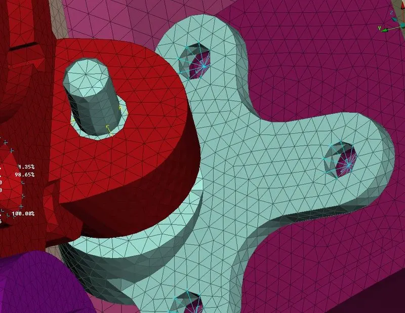
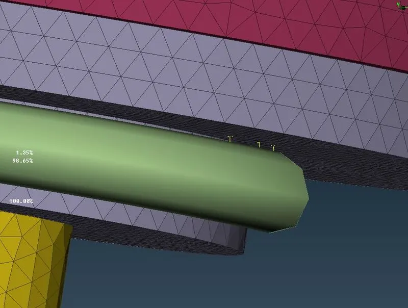
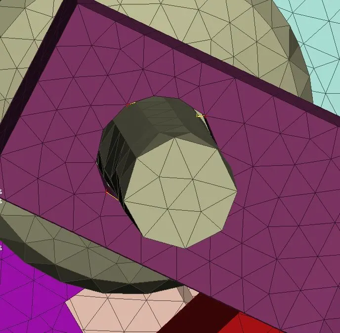
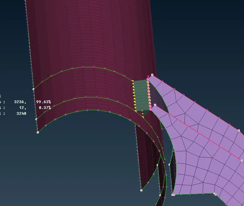
the above picture shows the seam weld representation, where the two sheet metals are connected.
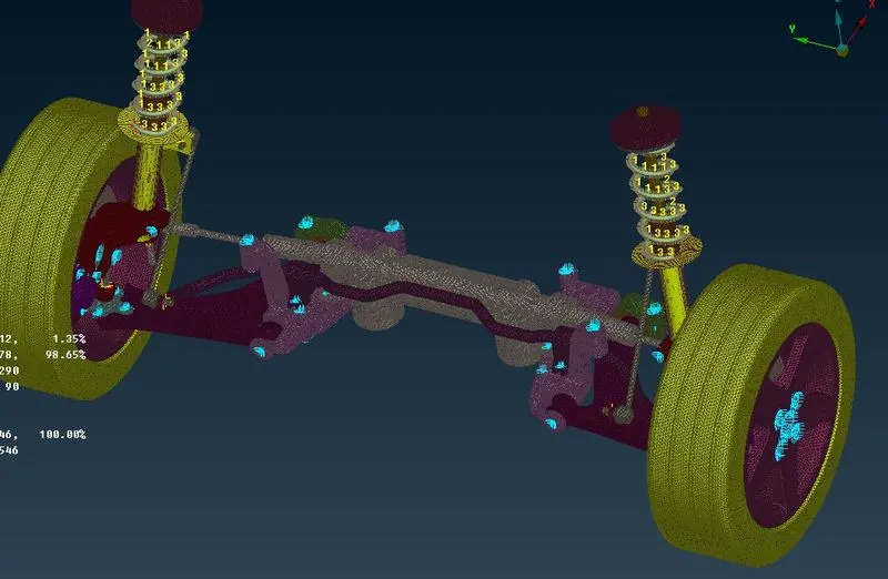
The above picture helps to visualize the overall connections in the model. Once the connections have been established, the finished half model can be reflected on the other side by using the transform command. Under transform command, the whole model is selected by using the entities and reflected the other side by using the mirror 3 points command and by selecting the 3 nodes on the model. On confirmation, the half-finished model is transformed into a whole new model.
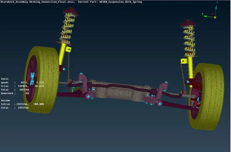
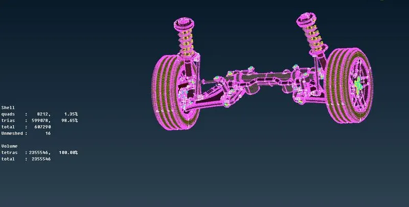
The picture illustrates the total number of 2D,3D, and zero off elements in the model. in addition it also represents the half model is transformed into a whole model.
Learning Outcomes:
I learned how to clean up the geometry in the topo module, how to mesh the different faces by using tria elements, how to eliminate the quality failures on tria elements, setting up the mesh and quality parameters, how to deal with the critical surfaces such as defeaturing, and how to achieve good mesh flow by giving manual cuts. Furthermore, I learned how to define the volume for the component in the volume mesh deck, how to mesh the volume with tetra Rapid and tetra Fem mesh and I learned how to eliminate the collapse failure in the volume mesh. I learned how to establish the connections on the model and why it is important. I learned how to establish the connection between rigid bodies and washer elements. I learned how to establish the connection by using many nodes and a two-node option in RBE2 elements. I learned how to establish the cluster connection. I learned how to transform the half model into a full model. More I worked I got familiar with the different options in the topo, mesh, and volume mesh module.
Conclusion:
After completing this specific Project, I would like to conclude that I get confident that I will achieve good mesh flow and quality 2D elements on the surface of any geometry. In addition to that, I could define the volume and mesh the volume with the given quality parameters. I could do the shell mesh and volume mesh on any given design. Further, I could provide the necessary connections to the model and if required I could able the transform the model. I conclude that it’s great learning.