Project - 2 - Meshing on the suspension Assembly
Project - 2 - Meshing on the suspension Assembly
AIM:
For the given assembly model, check for the geometrical errors and mesh with the given element Quality criteria. A. Also use appropriate connections as required between the parts of the assembly model
PROCEDURE:
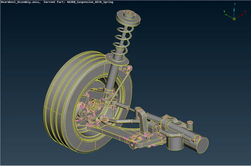
- Import the model in ANSA
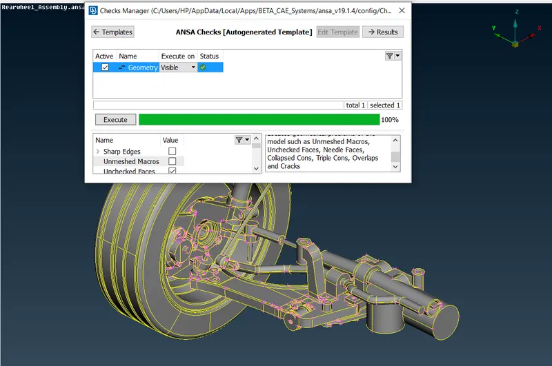
- Check for geometrical errors, Goto CHECKS > Geometry
- Fix the geometrical errors if thery are any
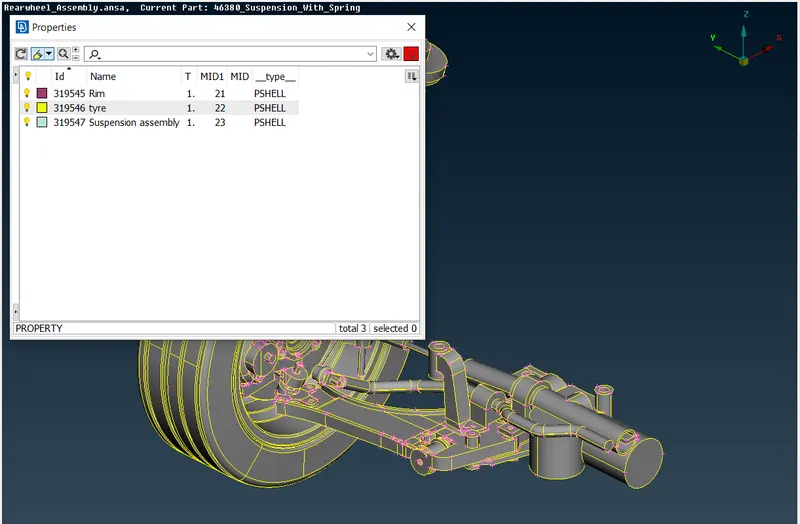
- The suspension model has three different PID's by default
- Tyre
- Rim
- Suspension assembly
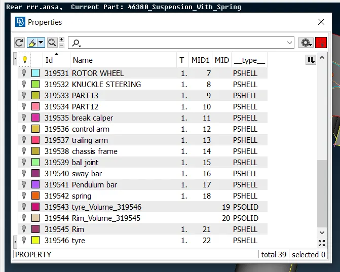
- Assign new PIDs for each part in the suspension system
- Goto Topo module > faces > setPID
- Give each parts their respective names for PID's
- Measure the thickness of each part and store them
- In the given model,there are two cases to be followed
CASE1: If the thickness is > 5mm ,For non uniform thickness Mesh the solid part, define volume and perform volumetric meshing
CASE2: If the thickness is < 5mm ,For uniform thickness Extract the mid-surface and perform 2D meshing
CASE1: Thickness > 5mm
- Mesh Generation for Tyre and Rim:
- Assign the quality criterias and mesh parameters
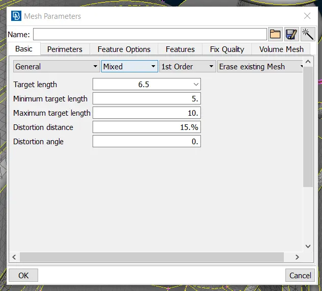
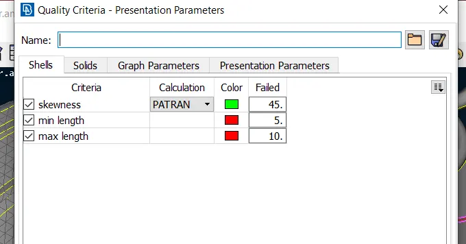
- Quality Criteria for Surface Meshing of Tyre and Rim (Element type: Tria)
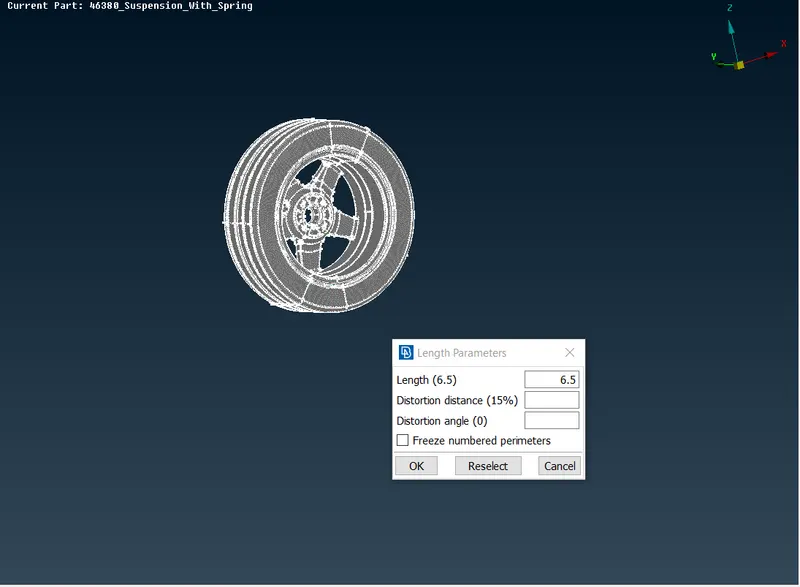
- Provide target length for the parts,Goto mesh module > perimeters > length
- Goto mesh module > meshgeneration > best
- Mesh the surface of the part,For Flat surfaces use tria elements
- For curved surfaces use orthotria elements for meshing
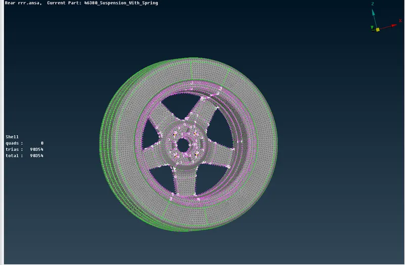
- Check for quality fails and clear them
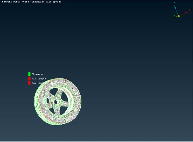
- After meshing , define volume
- For defining volume, Goto volume deck> Volume > Define
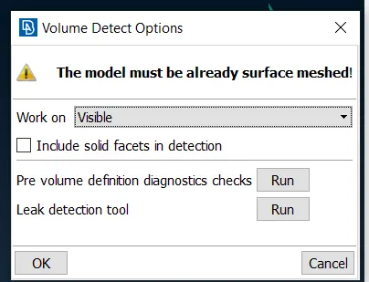
- For volume meshing ,use tetrarapid option and selct the defined volume for meshing
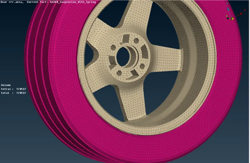
- Check for tetcollapse fail
- Given Quality Criteria for Volume meshing for tyre and rim (Element type: Tetra Elements)
- Goto quality parameters > solids > collapse
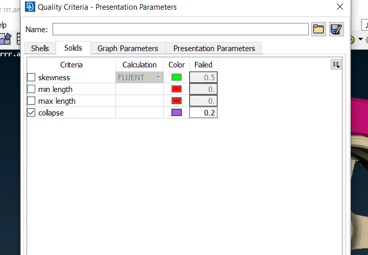
- Surface meshing and volumetric meshing for remaining parts
- Similarly follow the same procedure as tyre and rim for other parts with non uniform thickness i.e t > 5mm
- Assign quality and mesh parameters
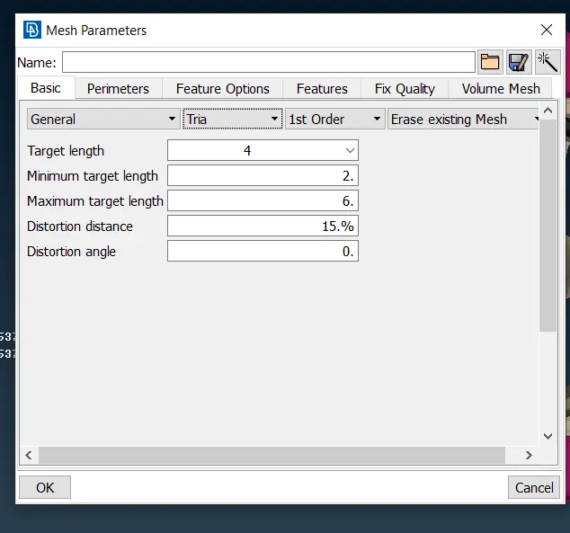
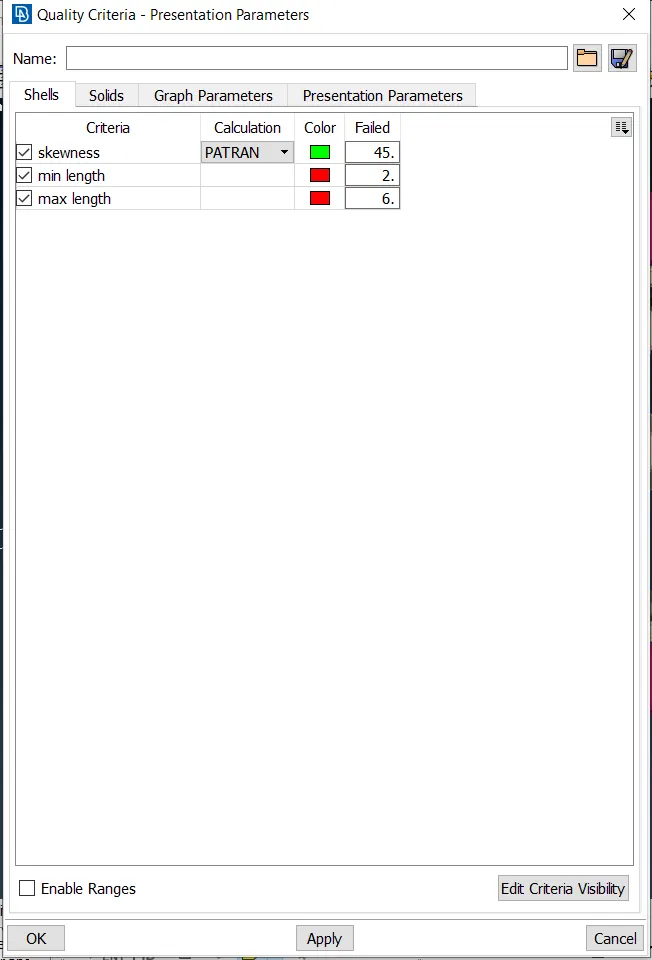
- Knuckle Steering
- Perform surface meshing , i.e trias on flat surfaces and orthotria on curved surfaces
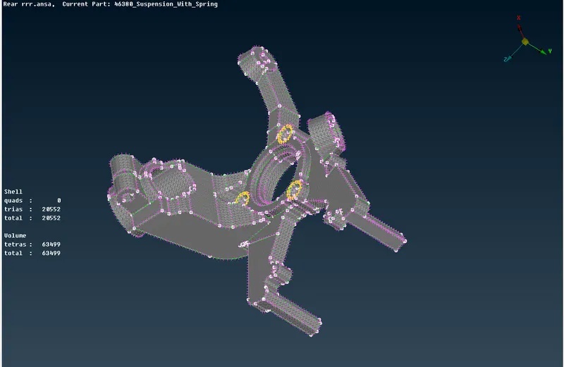
- Check for quality fails,clear if any
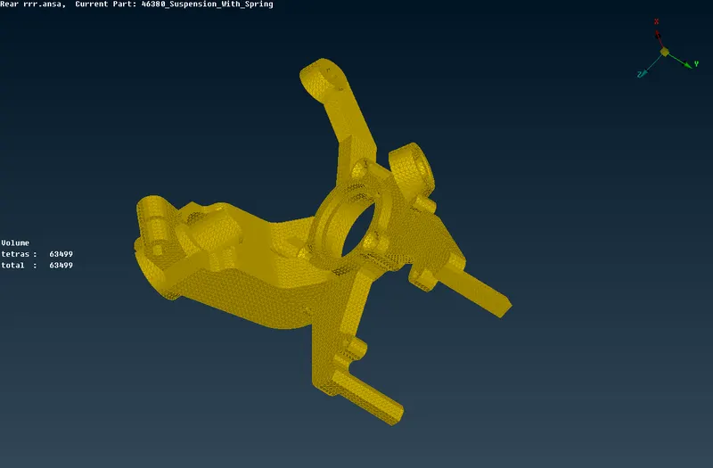
- Define volume for the part and Perform volumetric meshing using tetrarapid option
- Check for tetcollapse ,fix if any are present
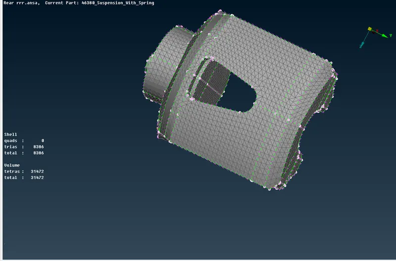
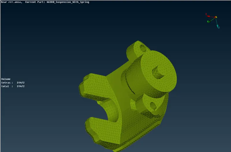
- Brake calliper:
- Chassis frame:
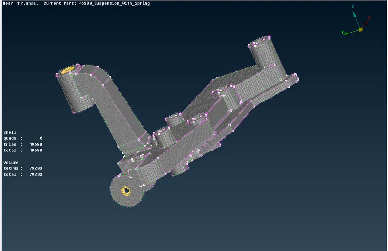
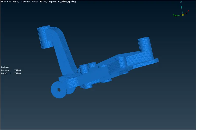
- Swaybar:
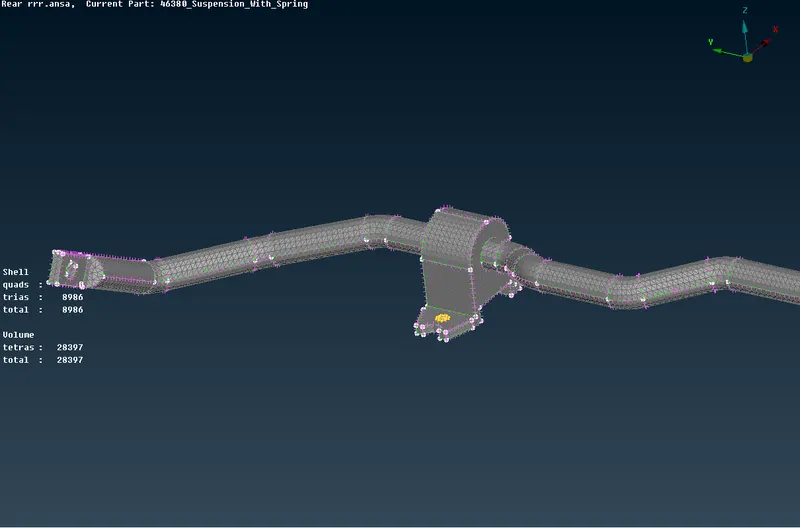
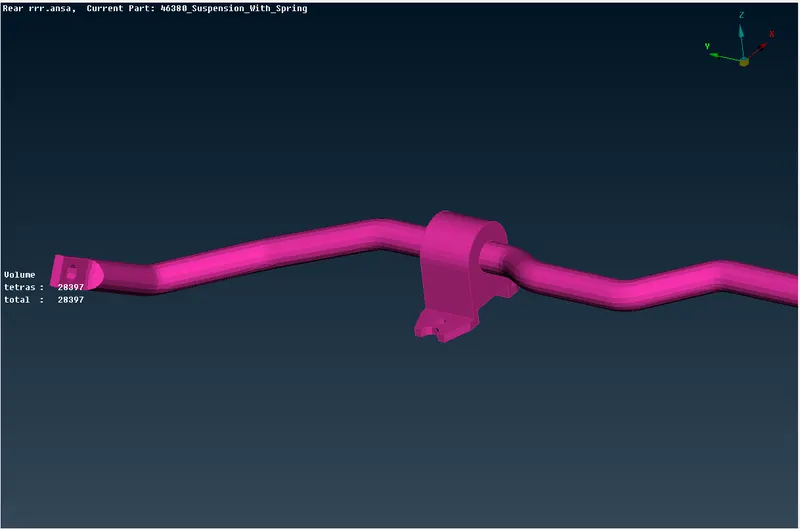
- similalry follow the same steps for other solid parts
CASE2: If the thickness is < 5mm
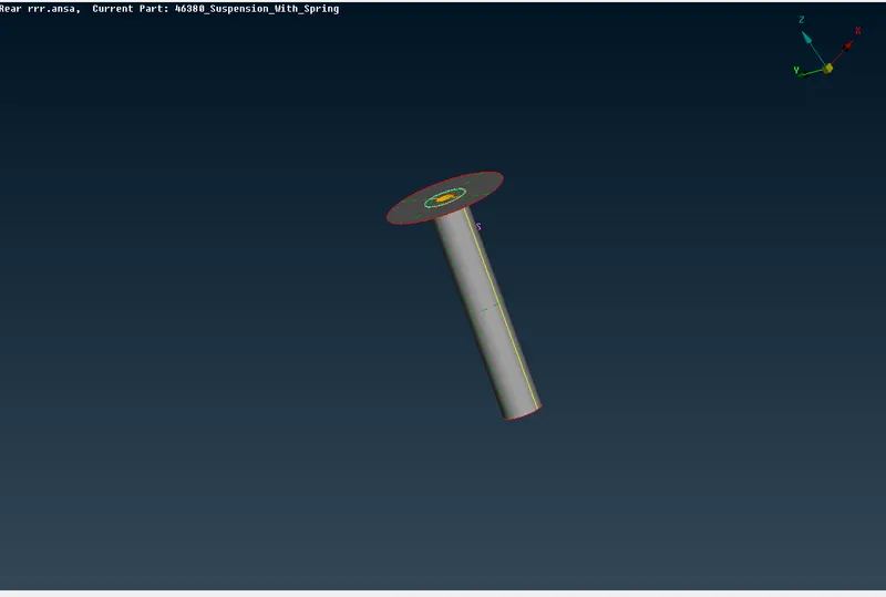
- For uniform thickness less than 5mm extract the midsurface
- Exract the mid by offset method
- Goto Topo module> faces> offset
- Select the faces to offset,use feature angle selection tool for better selection
- provide the offset value
- Assign mesh and quality parameters
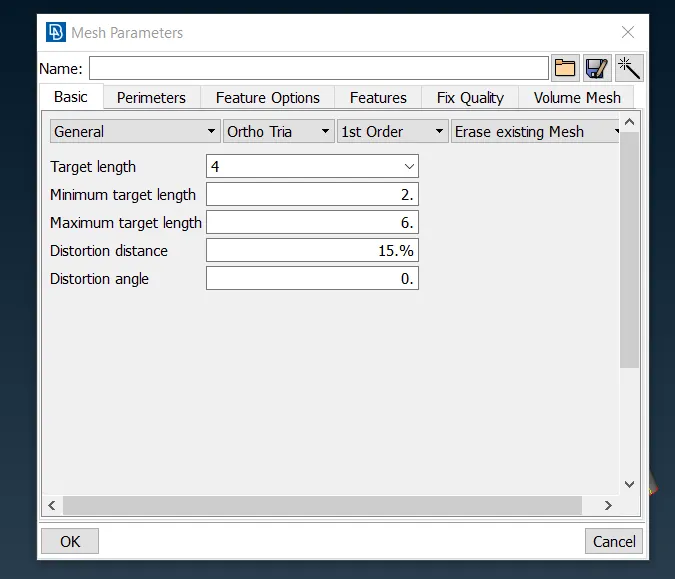
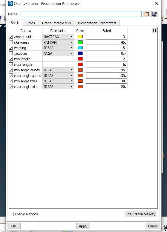
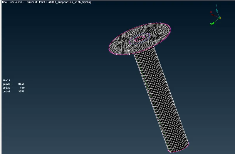
- Surface the mesh using BEST option
- Goto Mesh module> Mesh generation > BEST
- check for elements fail and clear them
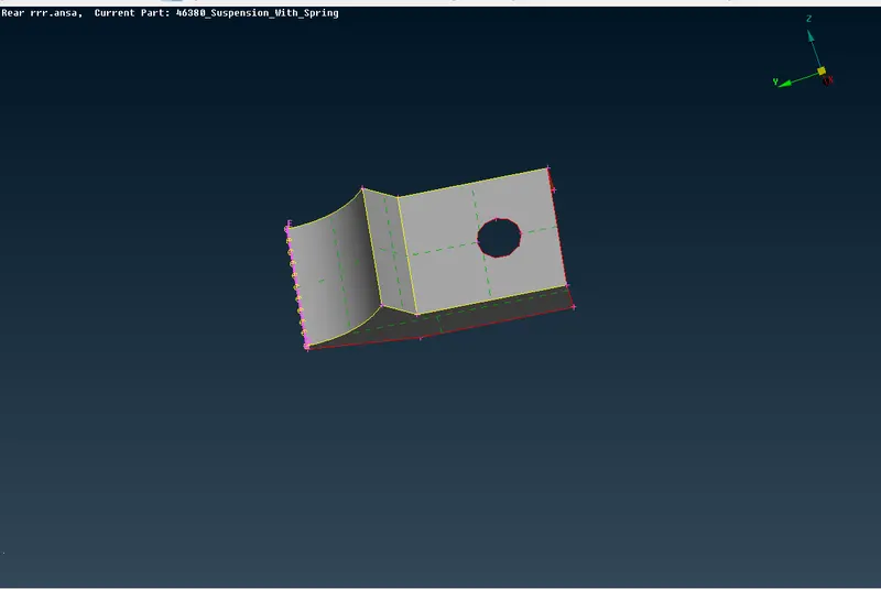
- For the next part ,extracted mid using skin option
- Goto topomodule > faces > midsurface > skin
- Uncheck the delete original faces from the options list
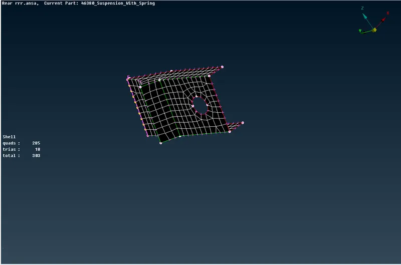
- Surface the mesh using BEST option
- Goto Mesh module> Mesh generation > BEST
- check for elements fail and clear them
- MESHING THE SPRING COMPONENT
- For spring component,we will be using 1D CBAR elements to represent the part
- First, generate a middle curve on the spring
- Goto topo module> curves > middle,select the 1st group cons and 2nd group cons on the spring
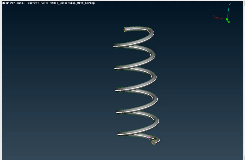
- Create and merge the curves as follows,Go to Curves > Connect > Multi
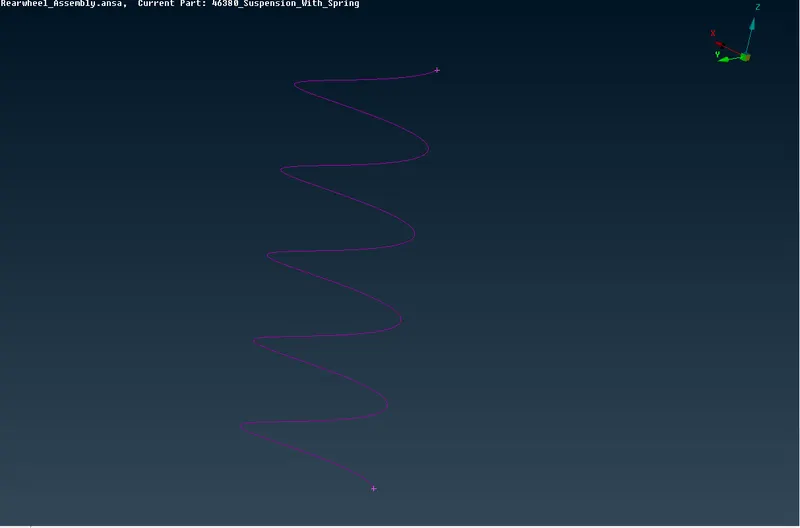
- Create a COG point on the generated curve
- Goto Topo module> Points > On C.O.G
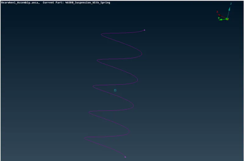
- Goto Nastran module > elements > CBAR
- Check orientation with nodes box and change the selection to Curve (box)
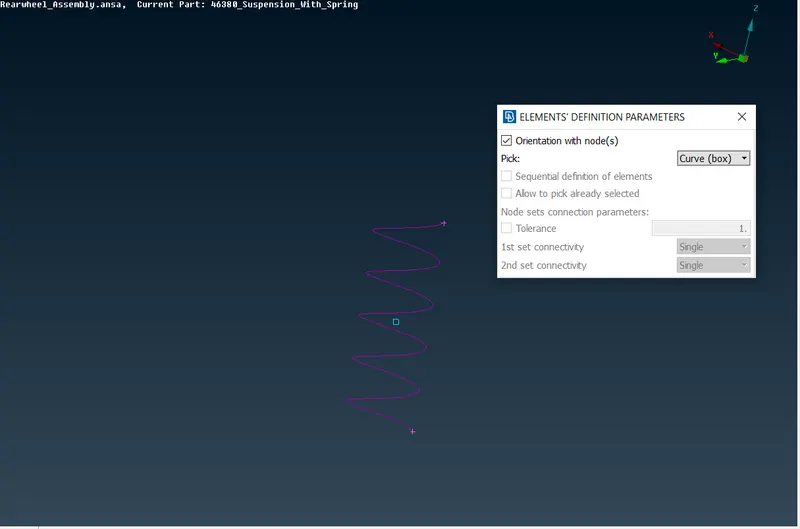
- Select the curve and slect the COG point as the orientation point
- specify the element length,i.e 4m
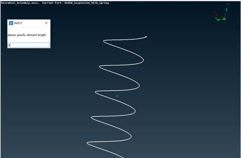
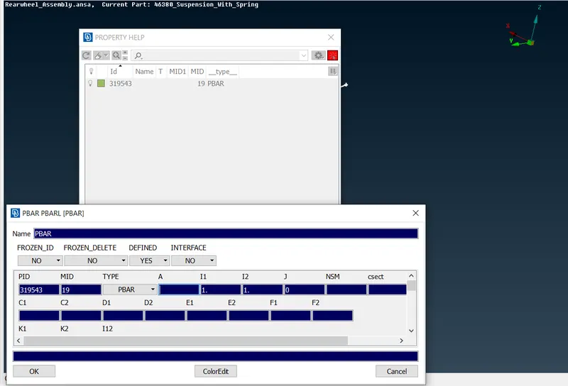
- Assign a property to this curve , i.e create a new PID
- In the area tab press shift + ?,give the radius
- After this , CBAR window appears , name it as spring
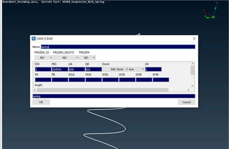
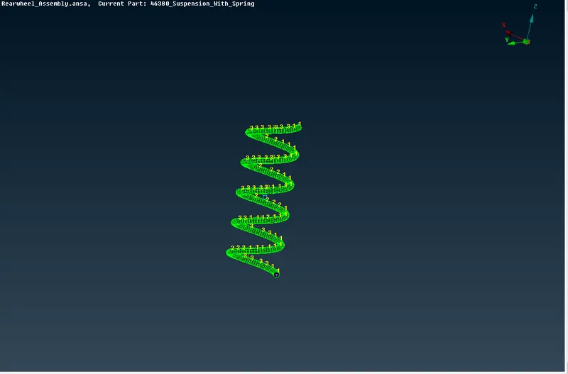
- Therefore the 1D respresentation of spring has been created
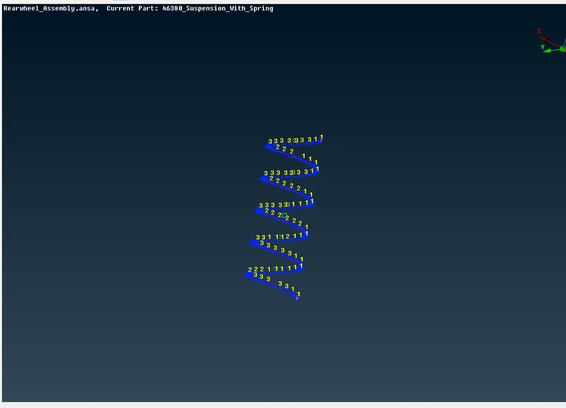
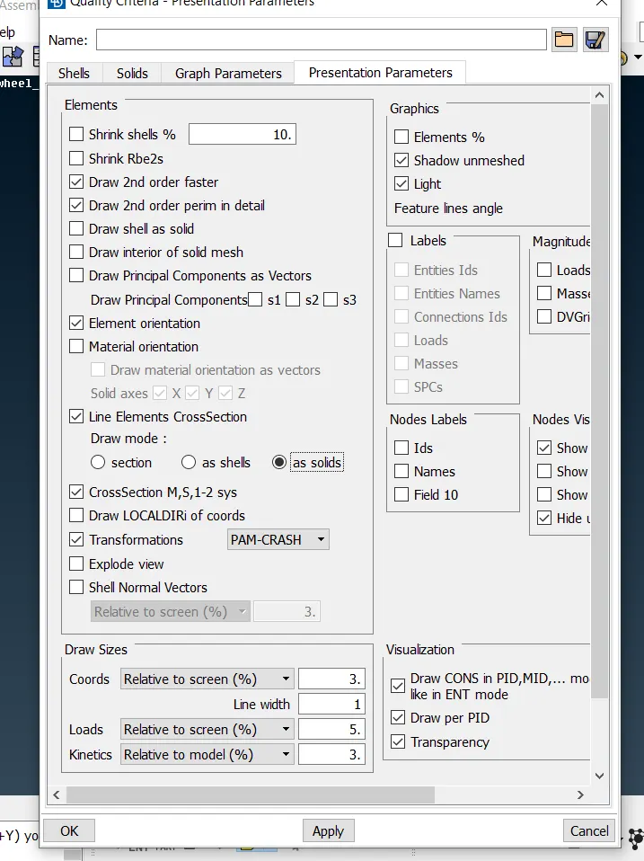
- To represent spting as solid goto quality parameters > presentation parameters
- Check the Lines Element Cross Section box and select as solids and click appply
- ie the 3D representation are as follows
CONNECTIONS:
-
To create a bolt connection, Goto Nastran deck > Elements > RBE2
-
RBE2 has two options ,ie many nodes and two nodesMany nodes creates connection between many slave nodes to a master node,while two node option connects two master nodes
- First create RBE separately for each hole ,Goto Elements > RBE2 > Many Nodes
- Select the slave nodes first,select loop tool for selection
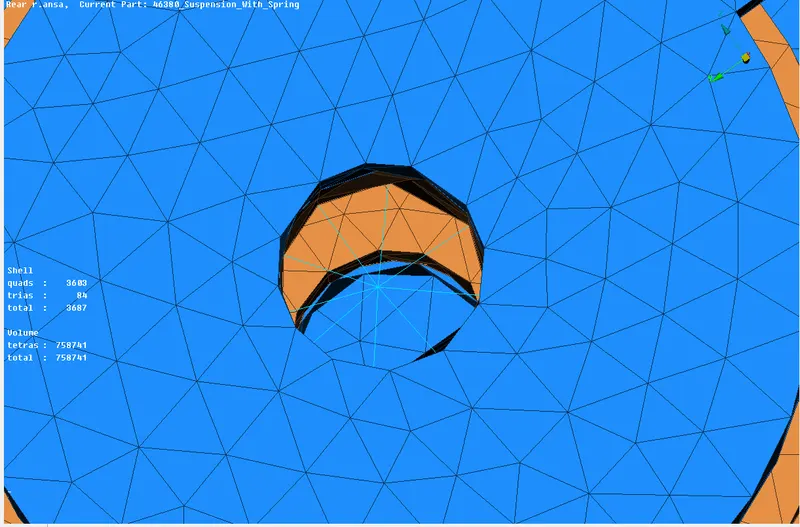
- Second connect the RBE2 by connecting master nodes ,Goto Elements > RBE2 > Two nodes
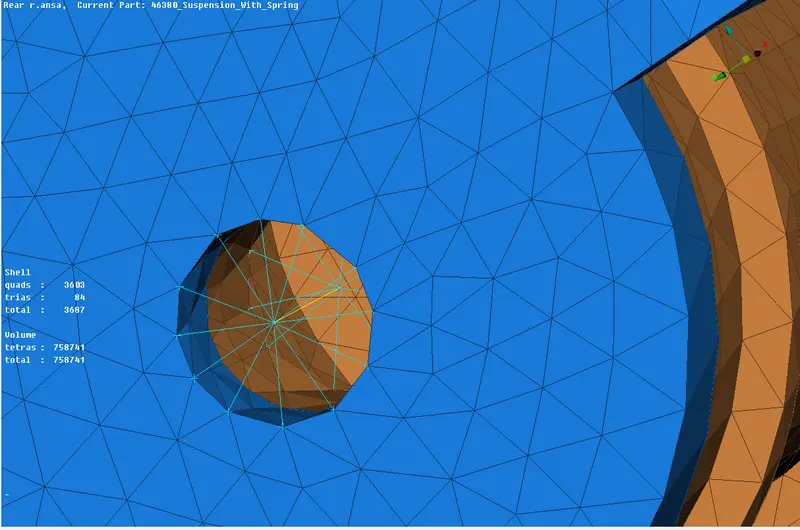
- Similarly follow these steps for all locations where a bolt connection to be deployed
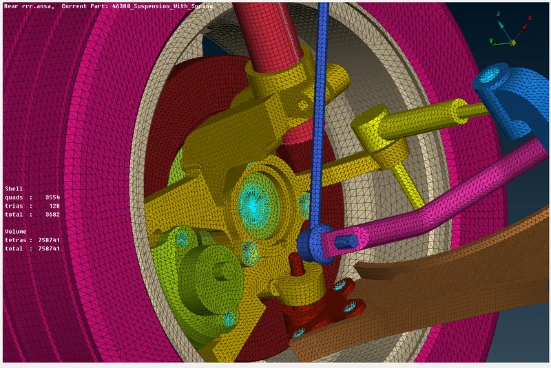
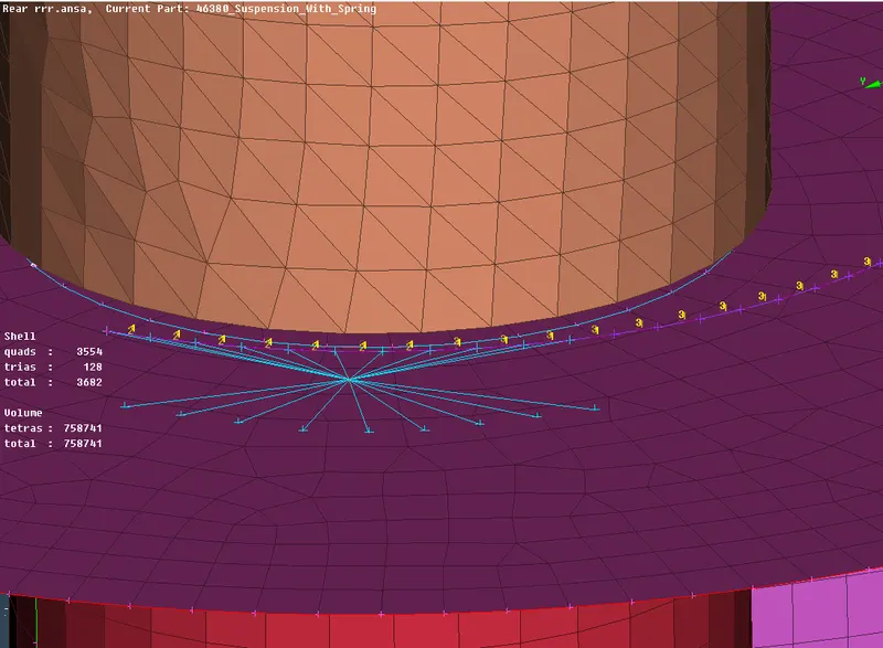
- Similarly spring elements need to be connected,for spring elments cluster RBE2 is required
- Goto Elements > RBE2 > Many Nodes
- Select the slave nodes in spring elements as well as in neighbouring elements
- ANSA will automatically detect and provide the master node
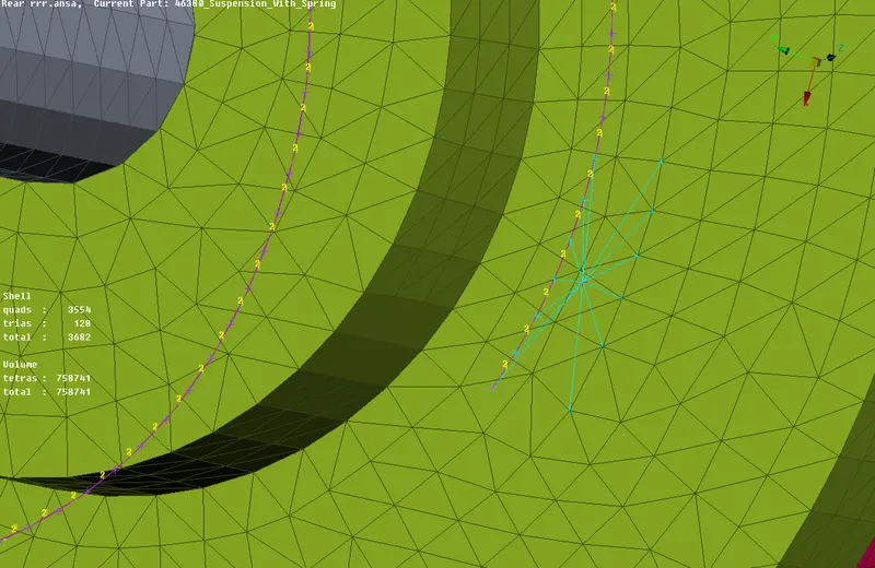
- Similarly provide connection for other side of the spring elements
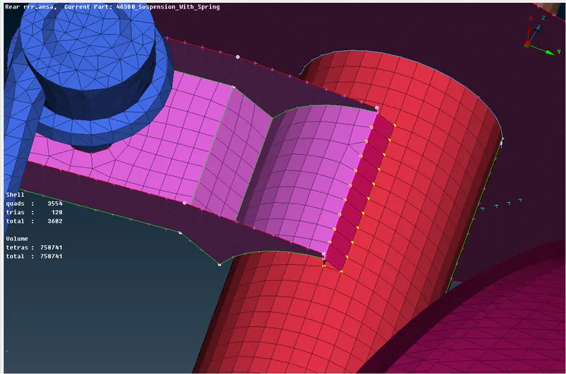
- Next type of connection is the seam weld connection.
- For seam weld connection create a curve first
- Goto Topo module > Curves > Cons2Curve ,select the edges
- Goto connections > seamweld
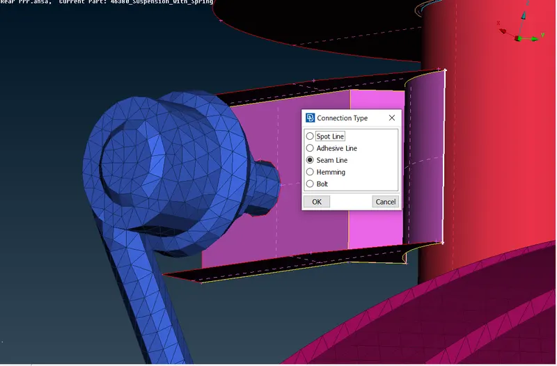
- The curve is converted into a seam line as shown below
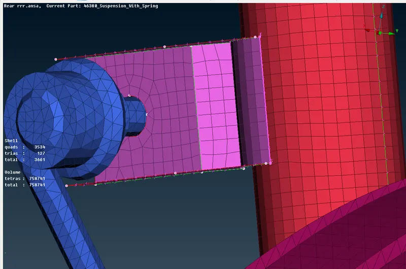
- Assign P1 and P2, Goto connections manager > select the seamweld curve
- To select the PIDs for each, right-click on P1 and in modify box press shift + F1 ,then select the part1
- Similarly for P2 select part2
- After assigning p1 and P2, Goto FE representation type , select OVERLAP SHELL
- Give search distance, width and step length as shown below
- Give target element length as width ,ie 4
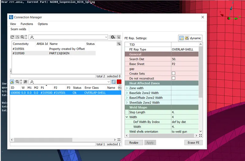
- After assigning values ,create a PID for seam weld,goto weld id and press shift + ? and create a new PID
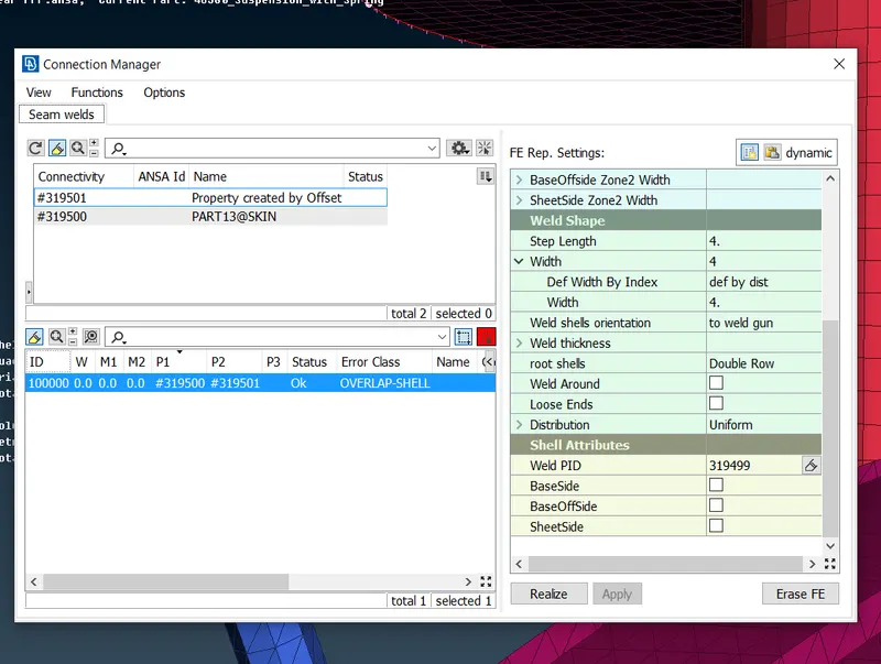
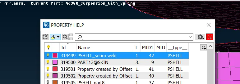
- After creating PID ,name it as seam weld , select realize and apply
- Hence the seam weld is generated
REFLECT the model :
- After performing meshing and deploying connection we go for reflecting the model
- Main objective of reflecting is that this produce exactly the other half of the model
- This is the final step in this model, For reflecting here we use Symmetry option
- Goto Transform > Copy > Symmetry
- Select the entities , go for a box selection and select the entire model
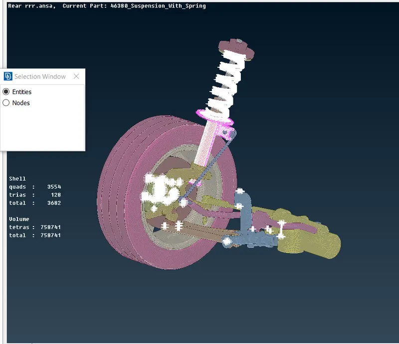
- Goto symmetry tab and change to mirror 3 point plane
- Define a new symmetry palne by selecting three points on the plane
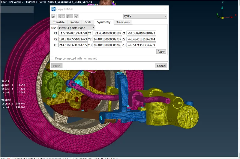
- click on apply and select finish, we will get the perfect half of the model
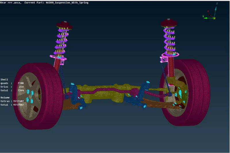
- Therefore the final result with the reflected model is shown below
LEARNING OUTCOMES
- Understood about various parts in suspension assembly of a car
- Understood about geometrical cleanup and assigning new PIDs
- Learned how to identify parts ,where to extract mid surface and where to use solid meshing
- Learned how to do volume meshing by using tetra elements
- Learned how to work with springs and how to use 1D CBAR elements
- Understood about connections and where to deploy the connections
- Learned about seam weld and how to create them
- Understood about RBE2 elements and how to make a bolt connection
- Learned about hoe to reflect a model and symmetry operation
CONCLUSION:
The given model was checked for geometrical errors and meshed successfully with 2D elements on the extracted midsurface and 3D elements on solid parts with the given quality and mesh parameters also connections were deployed at specific locations and finally reflected the model to get complete assembly