Project - 2 - Meshing on the suspension Assembly
AIM: To create a Tetra mesh in the rear-wheel assembly with proper mesh flow in it and to achieve quality criteria.
Objective:
i) Import the model into the ANSA GUI.
ii) After importing the model, check for any flawed surfaces, or damage in it.
iii) After clearing errors in the model, check for the geometry error by each component.
iv) Measure the thickness of each component due to varying in thickness.
v) Assign the part if they measure less than 5mm as a 2D shell or else a 3D element in a separate PID for each part.
vi) To mesh the Tyre & Rim use the following criteria file.
vii) To mesh another component with uneven 3D components, use the following criteria.
viii) For 2D mesh using the following criteria
ix) Assign the thickness for 2D shell components.
x) Reflecting the meshed component
Procedure:
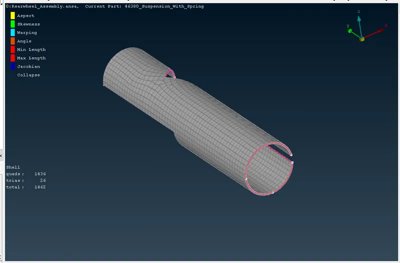
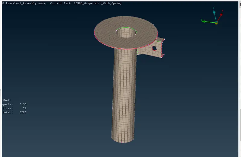
2D Shell component:
i) Measure the thickness of the component and assign them in separate PIDs.
ii) Check for the geometry error and once clear with it.
iii) Assign the length and macros to the model to follow the length of the mesh evenly throughout the component.
iv) Go for Mesh (mixed) element, and check for quality criteria
v) Assign the thickness for the component.
Quality Criteria for 2D shell element:
|
S.No |
Quality Criteria |
Value |
|
1 |
Target/Average length |
4 |
|
2 |
Minimum Length |
2 |
|
3 |
Maximum Length |
6 |
|
4 |
Aspect |
3 |
|
5 |
Warpage |
15 |
|
6 |
Skewness |
45 |
|
7 |
Jacobian |
0.7 |
|
8 |
Minimum Quad Angle |
45 |
|
9 |
Maximum Quad Angle |
135 |
|
10 |
Minimum Tria Angle |
30 |
|
11 |
Maximum Tria Angle |
120 |
3D Meshing:
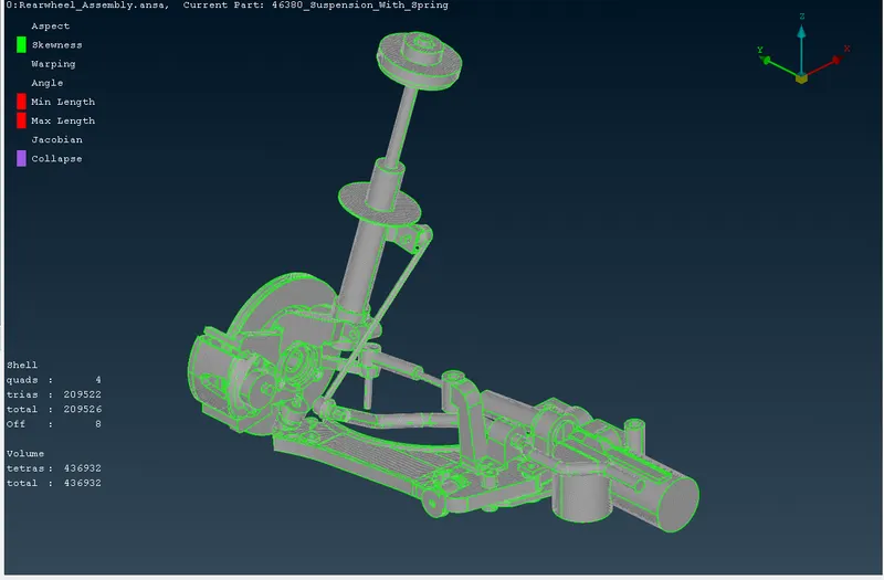
Un-Uniform thickness with more than 6mm, collect them and assign them to Separate PID
Once assign the PID, assign the length as per element size.
Then check for geometry error in the chosen model, and click execute.
Assign the quality criteria file, and mesh parameter files to ANSA GUI as per given.
Mesh element as Tria, and start the mesh by each component.
Check for the OFF element in it.
convert the 2D shell into a 3D element, by defining a new PID for it.
Quality criteria for 3D un-uniform element:
|
S.No |
Quality Criteria |
Value |
|
1 |
Target/Average length |
4 |
|
2 |
Minimum Length |
2 |
|
3 |
Maximum Length |
6 |
|
4 |
Skewness |
4 |
|
S.No |
Quality Criteria |
Value |
|
1 |
Tet-collapse |
0.2 |
Mesh of Tyre and Rim:
i) Uniform thickness with more than 6mm, collect them and assign them to Separate PID
ii) Once assign the PID, assign the length as per element size.
iii) Then check for geometry error in the chosen model, and click execute.
iv) Assign the quality criteria file, and mesh parameter files to ANSA GUI as per given.
v) Mesh element as Tria, and start the mesh by each component.
vi) Check for the OFF element in it.
vii) Convert the 2D shell into a 3D element, by defining a new PID for it.
Quality Criteria for tyre and Rim:
|
S.No |
Quality Criteria |
Value |
|
1 |
Target/Average length |
4 |
|
2 |
Minimum Length |
2 |
|
3 |
Maximum Length |
6 |
|
4 |
Skewness |
45 |
|
S.No |
Quality Criteria |
Value |
|
1 |
Tet-collapse |
0.2 |
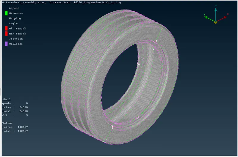
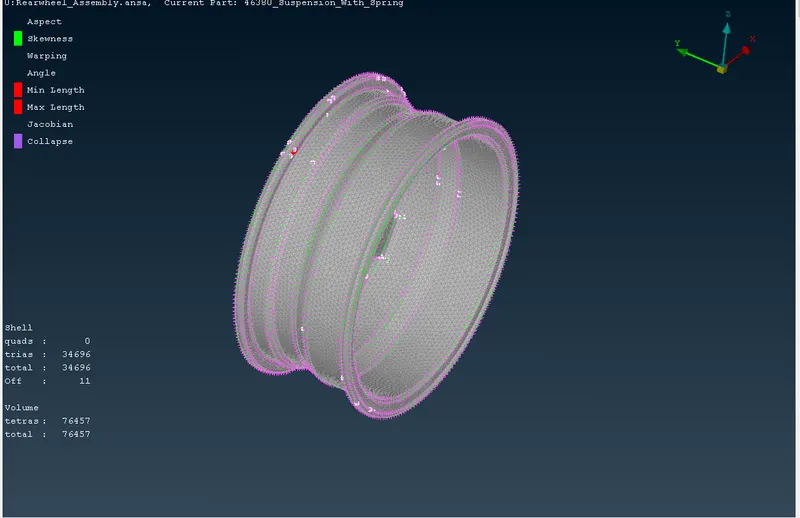
First, apply the quality given to the tyre and rim then by using the spot meshing option in the mesh generation which is in the mesh modules mesh the tyre and rim. select the mesh type as TRIA.
Use RECONSTRUCT option in SHELL MESH which is in MESH MODULE to improve the mesh quality and get rid of OFF ELEMENTS.
After completing the meshing on the tyre and rim we have to do the volume mesh on them. for that, we have to go to the VOLUME MESH module.
To do Volume meshing on any part of the model first we have to define the volume of the part. To define we have to use the DEFINE option in VOLUMES which is in the VOLUME MESH module.
After the volume is defined.By using TETRA ELEMENTS in UNSTRUCTURED MESH which is in a volume mesh module mesh the defined parts.
Using Connection:
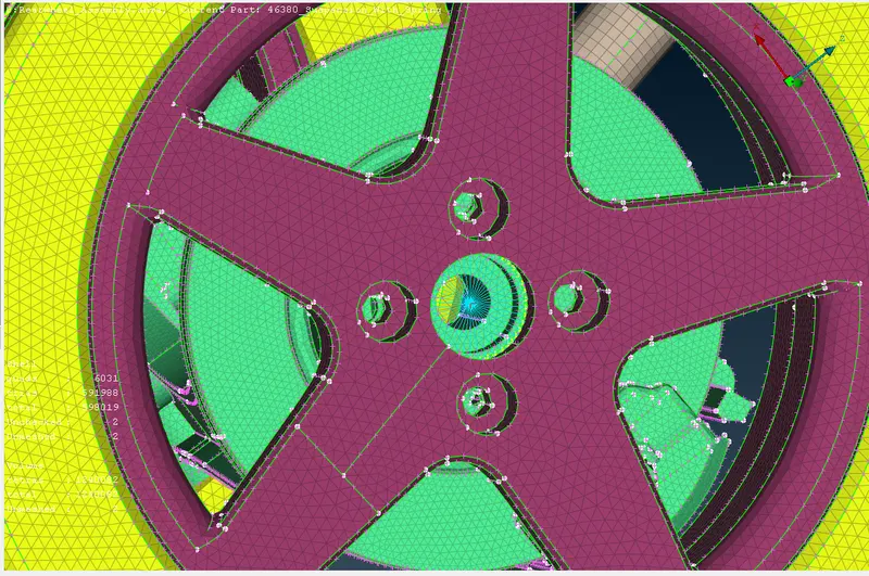
After the meshing on the suspension model is done we have to connect the parts by using CONNECTIONS by NASTRAN in DECKS MODULE.
Most of the connections in the model are RBE2 connections which can be done by using the RBE2 option in ELEMENTs which is in DECKS MODULE. To perform RBE2 connections click on RBE2 and select the nodes in the place where u want to create the connection and then confirm it and the connection will be created. Nodes can be selected in many ways by using NODES OR ENT options in the FEATURE SELECTION OPTION.
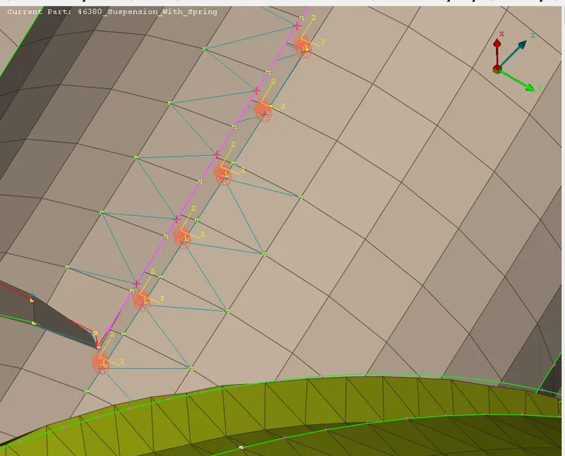
We also have some parts in which we have to perform the SEAM WELD CONNECTIONS. So to perform seam welding connections we have to first create a curve using the CONS. For creating curves by using cons we have to use the CONS to CURVES option in CURVES which is in the TOPO module.
Then the curve should be converted to a SEAM LINE by using the CONVERT option in the ASSEMBLY OPTION. (Assembly < convert< curve< seam line).
After the SEAM LINE is created we have to go to ASSEMBLY < CONNECTIONS< (select the seam line created ) < (select the two parts and assign them SHIFT+? when the seam connections need to be created)< (select RBE3 CBUSH RBE3 to give the different info like distance, width and assign different PID.)<and then realize the connection for seam weld connection to be observed.
For Spring Element:
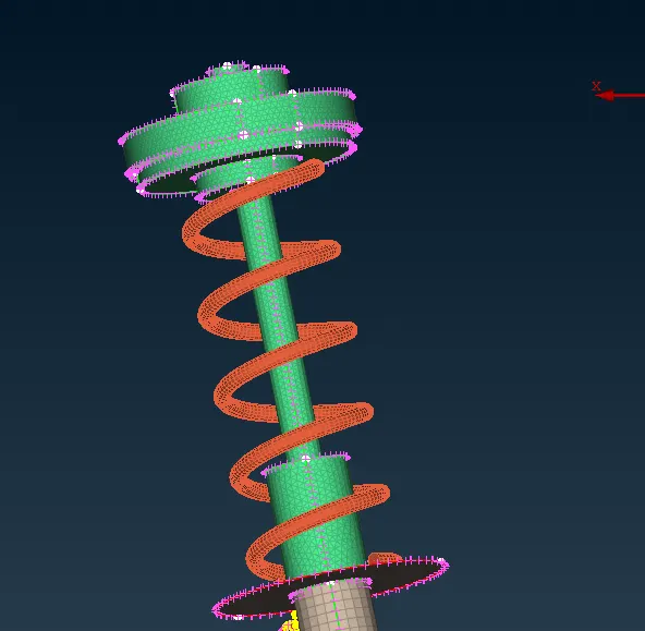
In the suspension assembly, we have a spring in which a PBAR connection needs to be created. So for creating the CBAR CONNECTION we have to first create a curve by using the CURVE MIDDLE option in CURVES in TOPO MODULE. and connect it by using CONNECT option.
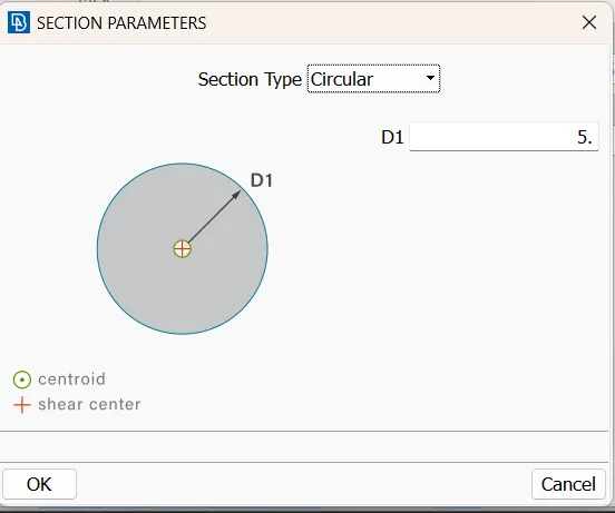
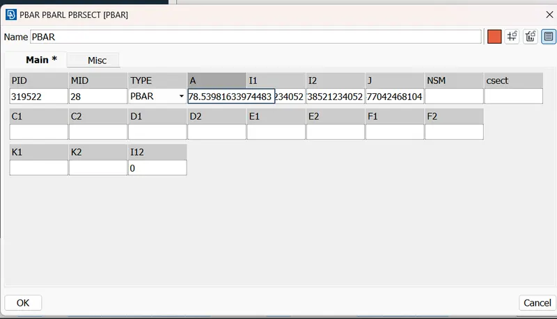
After the curve is created we have to create the CBAR CONNECTION by using the CBAR option in ELEMENTs which is in NASTRAN DECKS. NASTRAN DECKS < ELEMENTS < CBAR
Use the Symmetry option:
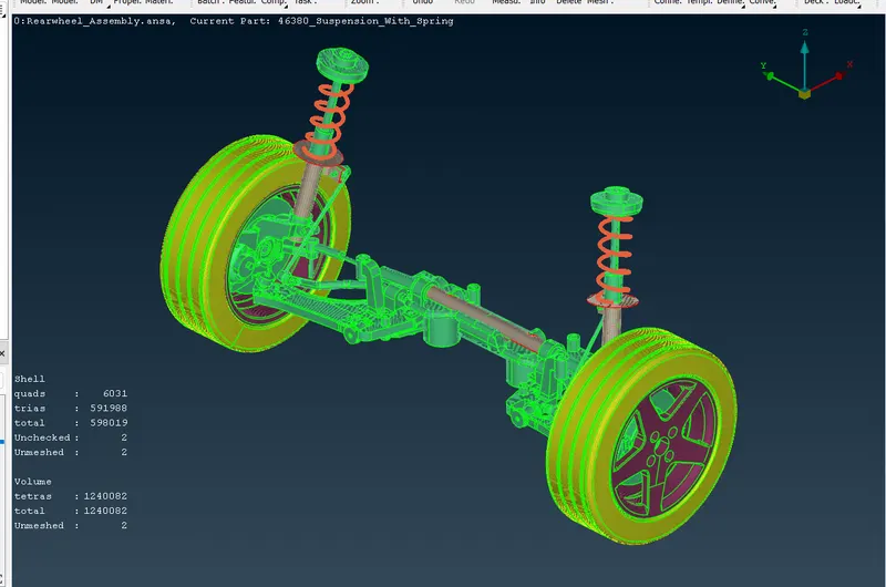
After all the meshing and connections are completed on the model we have to now REFLECT the model by using the SYMMETRY command to finish the model to the other side.
To perform symmetry first go to UTILITIES< TRANSFORM<COPY(entities)<SYMMETRY<(give 3 coordinates) and press finished to get the reflection of the model on another side.
Conclusion:
As per the varying thickness of the suspension, a model is been meshed with proper quality criteria, uses appropriate parameter criteria with some connections, and performs the symmetry done by using the transform option.
Google Drive Model:
Suspension model:
https://drive.google.com/file/d/1FM9Fv4T5hvHg5djhlZ-YQDj_wzrebfcc/view?usp=sharing