Project - 2 - Meshing on the suspension Assembly
AIM: In this challange our objectives are to mesh the components in the assembly as per the quality criteria and mesh mesh parameter provided. And using appropriate connection in the suspension assembly.Creating other half of the assembly by symmetry command.
PROCEDURE:
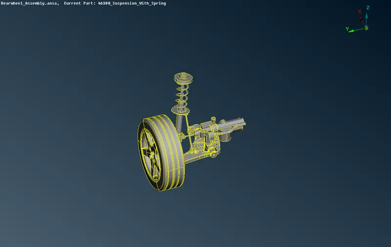
- Firstly we will improting the CAD model to the ansa workspace.
- If required we will perform topo function to arrange the faces and geometry of the model by selecting the TOPO from topo module.
- After TOPO we perform for geometry check, by clicking on the Checks tool on tools toolbar.
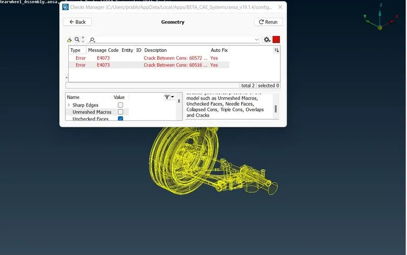
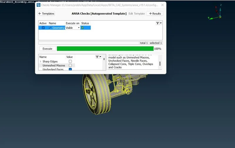
- We will rectifying the errors appear by the geometric check manually or automatically.
- After clearing all the errors we will again check for the errors.
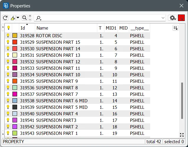
- After this we will set PID as per different parts in the geometry .
- For components wich are having thickness less than 5mm we will go for mid surface extraction and then meshing.
- As in this model their is component which is having thickness of 3 mm so we will take Mid Surface and mesh as per the given quality criteria.
- After taking mid surface extraction we will set mesh parameter and delete unwanted hard points on the model to get proper mesh flow.
- With Best in mesh option we will start meshing the component with mix mesh.
- If required we will reconstruct the mesh to get desired quality as per the given criteria.
Quality criteria for Mid Surface of uniform thickness components (Element Type-Mixed)
| S. No. | Quality Criteria | Value |
| 1 | Target Length | 4 |
| 2 | Minimum Length | 2 |
| 3 | Maximum Length | 6 |
| 4 | Aspect Ratio | 3 |
| 5 | Warpage | 15 |
| 6 | Skewness | 45 |
| 7 | Jacobian | 0.7 |
| 8 | Minimum Quad Angle | 45 |
| 9 | Maximum Quad Angle | 135 |
| 10 | Minimum Tria Angle | 30 |
| 11 | Maximum Tria Angle | 120 |
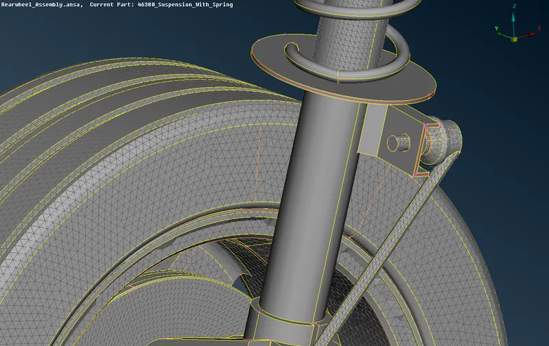
- In PID we will assign thickness for the component.
- Now for rest of all other non uniform thickness parts we will go for ortho tria meshing firstly we will do 2D meshing then we will go for Volume meshing on the componenets.
- At first we set parameters as for Tyre and Rims their is different parameters and rest other parts have different parameters.
Quality For Surface meshing for Tyre & Rims (Element Type-Trai)
| S. No. | Quality Criteria | Value |
| 1 | Target Length | 6.5 |
| 2 | Minimum Length | 5 |
| 3 | Maximum Length | 10 |
| 4 | Skewness | 45 |
Quality For Surface meshing for Non Uniform thickness coponent other than Tyre and Rim (Element-Tria)
| S. No. | Quality Criteria | Value |
| 1 | Target Length | 4 |
| 2 | Minimum Length | 2 |
| 3 | Maximum Length | 6 |
| 4 | Skewness | 45 |
- Before meshing we will clean up the geometry properly , just to avoid the feature area/ lines.
- For Volume Mesh We will first do the surface mesh using Tria and Ortho Trias and the converting those surface mesh to volume mesh.
- For surface meshing we will preffer Spot mesh and Best Mesh for 2D meshing.
- We will prefer Ortho tria as their are very much curved surfaces present as it will capture it more accurately as compared with normal trias.
- To have Good Mesh Quality we will reconstruct the mesh in order to get proper mesh flow and OFF elemets in model.
- Now we have to keep note that their should not be Kink and Rise in the model.
- If these are present in the model we have to remove it in order to avoid Tet collapse issue.
- After meshing we have converted the surface mesh into volume mesh.
- For that first we have to define the component and then List the component and REMESH it with Tetra FEM.
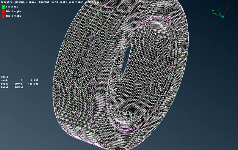
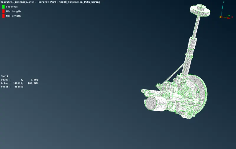
- After meshing with zero errors we will go for volumem meshing.
- For Volume mesh we have to define the volume first for that we will click on Define under volume in volume mesh module.
- We will select automatic Visible then it will automatically check for Some errors in mesh geometry which we will rectify and move ahead to next process.
- After unchecking the unecessary errors we will close the window as automatically it has selected all the visible volumes.
- Then we will go to LIST and then defining the type and remeshing the componenets individually.
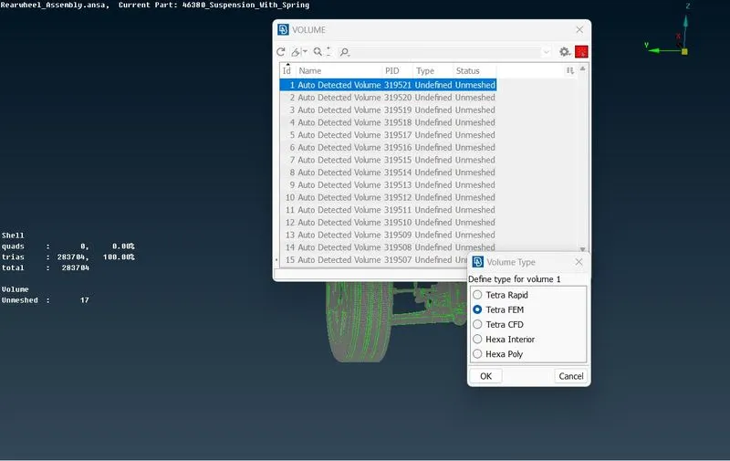
Quality Criteria For Volume meshing-
Tet Collapse-0.2
- If their is any quality failure present we will rectify manually or automatically by a fix quality or move commands.
- Now after clearing all gerometrical errors we will go for creating 1D Bar element.
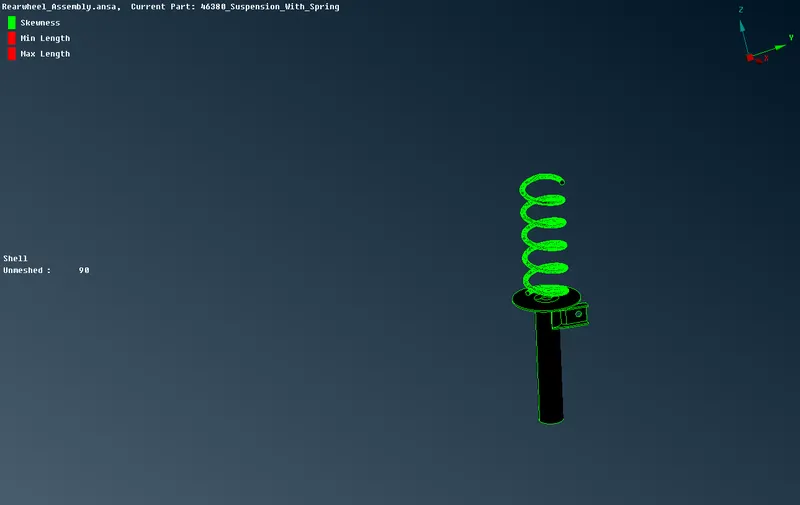
- To generate spring we will have to create first middel curve from the CAD geometry.
- Then we will Join the curves as it will be in multiple parts.
- Then we will create COG point for the curve to defin the orientation.By points then ON COG
- Then we will go to NASTRAN Deck, and selecting CBAR.
- Then changing the selcetion type to CURVE BOX
- Selecting the curve and give middel mouse click and also selecting the orientation node, now we will specify the element length. In this case element length is taken as 4mm, hit middle mouse click.
- After specifying the element length as 4mm, now we will defining PID by creating new PID in property tab.
- We will define area by giving radius of spring. After that assign the cross sectional radius of the spring element.
- With Middel mouse button it will calculate cross sectional area and moment of inertia. 1D Bar element will be created.
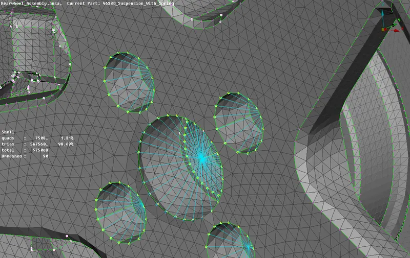
- In model we will also provide appropriate connections. As in bolted part we will provide Cluster RBE2 connections.
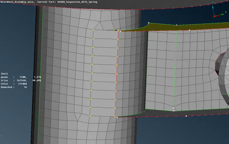
- For weld parts we will provide seam weld connections their.
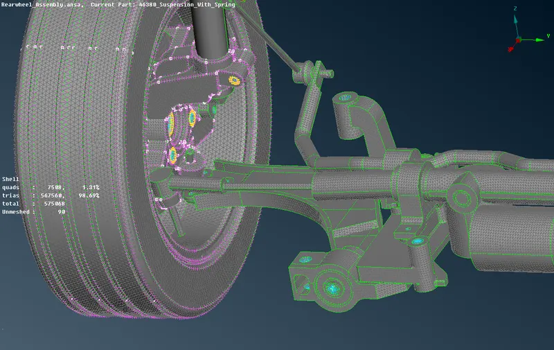
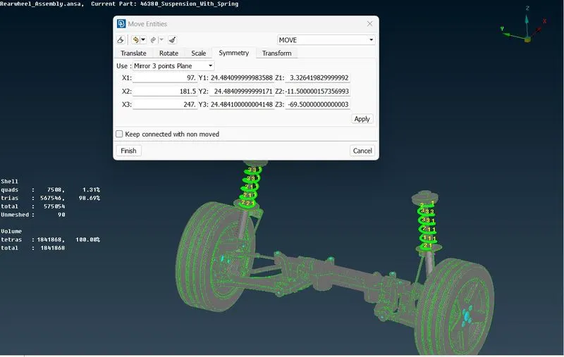
- Now we will copy half model to make it complete, for that we will carry out symmetry option.
- For that we will go to transform option then copy.
- Then selecting all the entities which have to symmetry.
- Now going to symmetry tab and selecting Mirror 3 point Plane.
- Selecting Three symmetric Points then click on apply option and Finish.
LEARNING OUTCOME:
- Learned to fix the geometrical errors.
- Learned to extract Mid surface form the uniform thickness components.
- Learned to perform meshing operation with proper mesh flow.
- And also learned to fix the mesh errors present in the model by various methods.
- Learned to define volume and volume mesh with Tetra FEM.
- Learned to defeature the area to avoid mesh errors.
- Learned to fix Dips and Kinks in a volume mesh.
- Learned to deploy connections PBAR and RBE2 with many nodes and two nodes.
- Learned to copy entity with symmetry command.
CONCLUSION:
Finally we have completed meshing of model as per given meshing parameter and quality criteria. By using appropriate connection we have connected the assembly and also performed symmetry command to reflect the half finished model.
https://drive.google.com/file/d/1yw7x2Lh85VGXBWm_-30CHRxMCagHza1f/view?usp=sharing