Project - 2 - Meshing on the suspension Assembly
Project-2 Meshing and connection of Wheel and Suspension Assembly
AIM:
To generate a 2D mesh for the given Wheel and Suspension Assembly model by taking Mid Surface for Uniform Thickness component and Volume mesh for Tyre, Rim, and other Non-Uniform thickness components present in the model after clearing the geometrical errors present in the model followed by Quality Criteria Check. Then providing connections at the desired locations.
PROCEDURE:
The following diagram provides the flow chart of the work being progressed for meshing the given Wheel Assembly model.
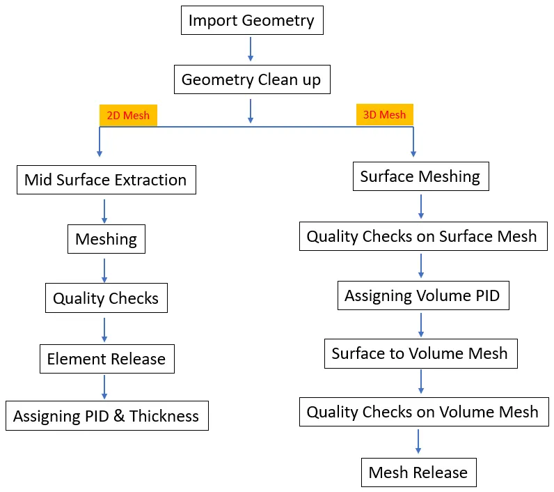
Fig.1 Flow Chart
Geometry Import: First the Wheel Assembly model has been imported to the Ansa software and preliminary checks on the geometry have been carried out. The preliminary checks include the geometry error checks. If any errors present in the model were cleared later. Figure 2 provides the topological/geometrical model imported into ANSA.
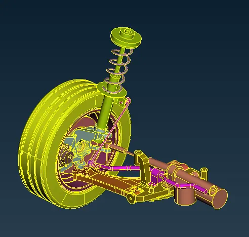
Fig. 2 The Wheel Assembly Model imported into ANSA Software
Geometry Clean-up: The geometrical errors present in the model have been cleared and the below figure provides a visual aid for the cleared geometry.
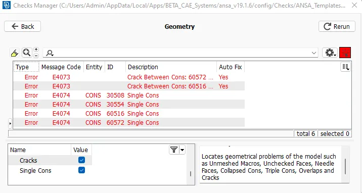
Fig. 3 Geometrical Error Check made on the model.
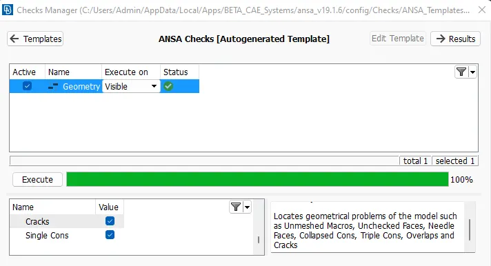
Fig. 4 Geometry Errors cleared.
The model has been checked and cleared for geometrical errors. Figure 4 shows that the given model is free from geometrical errors. After that orientation of the model has also been carried out.
1.2D MESHING:
Mid Surface Extraction: For mid-surface extraction FACES-OFFSET option for some parts because the parts are of the T section, where we can’t use the MIDDLE option to extract the middle surface, and the FACES-MIDDLE option for other parts which have symmetrical surfaces at the top and bottom was used. After the model has been cleared for the geometrical errors, the Mid Surface of the Uniform Thickness component has been extracted by splitting it into many parts for easy extraction and meshing followed by assigning a separate PID for each. For easy Mid Surface Extraction, the model has been separated into many parts as shown in figure 5. Figure 6 shows the mid surface of the entire model and figure 7 provides details of the PID assigned respectively.
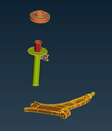
Fig. 5 Split Up Portion of the Given Model.
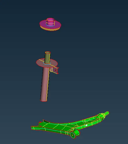
Fig. 6 Mid Surface Extracted for each Component.
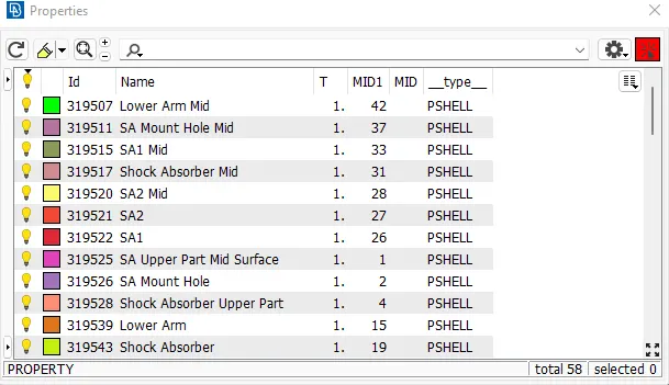
Fig. 7 Separate PIDs assigned for each component with respective thickness.
Meshing: After Mid Surface Extraction, meshing has been carried out on the mid-surface with the following mesh parameters shown in figure 8.
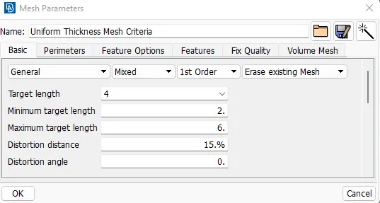
Fig. 8 Mesh Parameters.
Figure 9 shows the mesh created on the mid-surface extracted.
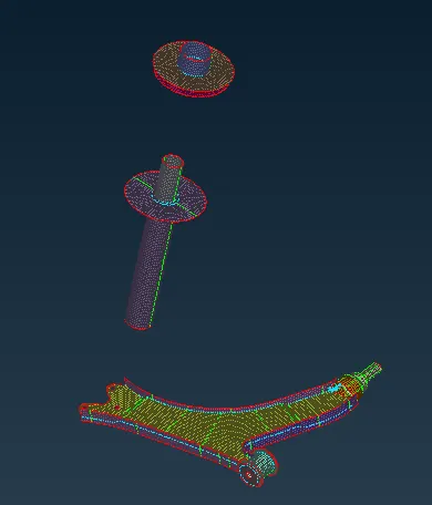
Fig. 9 Mid Surface Meshed.
Quality Checks: After mid-surface meshed, quality checks have to be performed and the mesh should be free from quality errors. Figure 10 shows the Quality Criteria set for the given model.
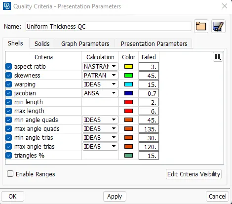
Fig.10 Quality Criteria Check.
The quality check was performed and quality errors were cleared. The mesh model free from quality error is shown the figure 11.
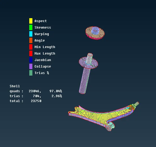
Fig. 11 Quality Checks performed on the mesh.
Element Release: After the quality checks, the mesh elements were released from the mid surface and assigned to a separate PID. Figures 12 and 13 show only the mesh model and PIS data for the model.
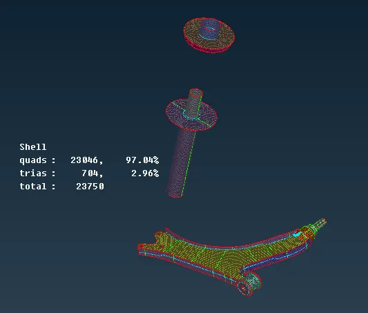
Fig. 12 Mesh-only Model.
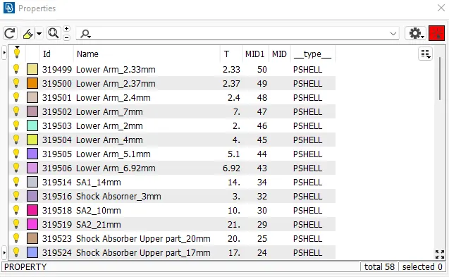
Fig. 13 Mesh PID Details.
Assigning Thickness: The model has been provided with respective properties namely Thickness, Material, Name, and Ids. Finally, the elements were drawn as solids. Figure 13 shows that thickness has been assigned to each component and figure 14 & 15 shows the mesh elements of the entire model drawn as solids to reflect the actual CAD geometry.
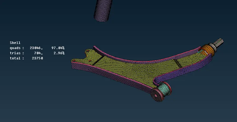
Fig. 14 Elements drawn as solids.
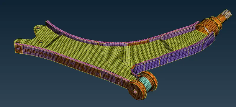
Fig. 15 Elements drawn as solids of meshed model and original CAD model.
2.3D-VOLUME MESH:
1. Tyre and Rim:
Surface Meshing: For Volume mesh, meshing has been carried out on the surface of the tyre and rim with the following mesh parameters shown in figure 16.
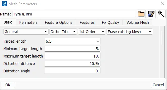
Fig. 16 Mesh Parameters.
Figure 17 shows the mesh created on the surface.
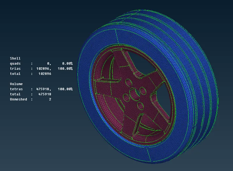
Fig. 17 Surface Meshed.
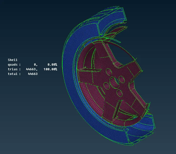
Fig. 18 Cross Section - Surface Meshed.
Surface Mesh Quality Checks: After surface meshing, quality checks have to be performed and the mesh should be free from quality errors. Figure 19 shows the Quality Criteria set for the given model.
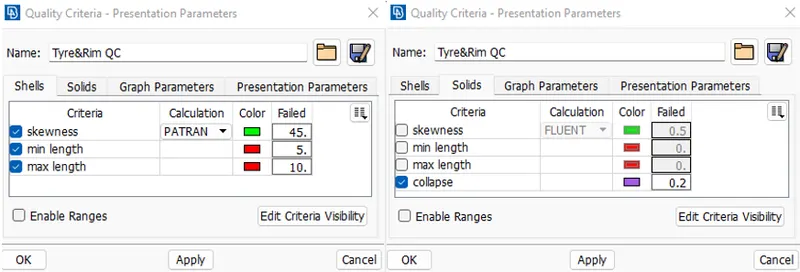
Fig.19 Quality Criteria Check.
The quality check was performed and quality errors were cleared. The mesh model free from quality error is shown the figure 20.
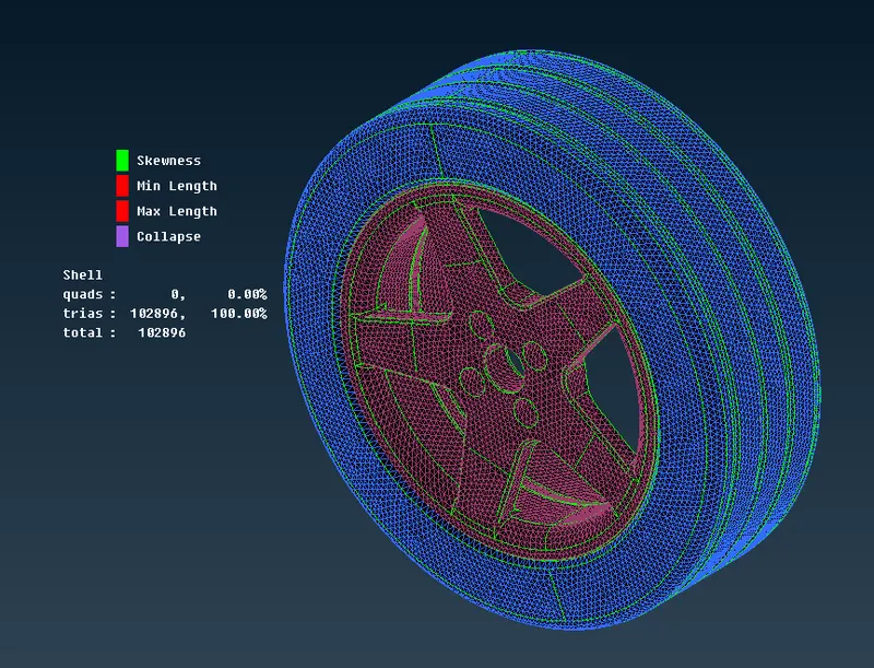
Fig. 20 Quality Checks performed on the mesh.
Assigning Volume PID: After clearing all the quality issues on the surface mesh, the volume has to be created for generating 3D mesh. So each component of the model has been declared as closed volume and separate PIDS were assigned as shown in figure 21.
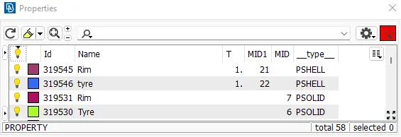
Fig. 21 Volume and PIDs assigned for each Component.
Surface To Volume Mesh Generation: After declaring closed volume, the Unstructured Mesh type is used. Under the Unstructured mesh tab, Tetra FEM or Tetra Rapid type of meshing can be selected. In this model, the Tetra FEM type meshing algorithm is used and 3D mesh is generated. Figures 22, 23 & 24 show the meshing algorithm type, 3D meshed model, and cross-section of the volume mesh.
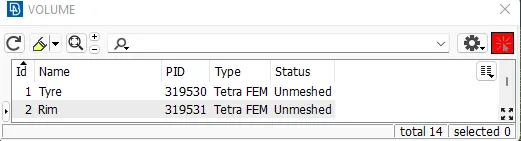
Fig. 22 3D Meshing Algorithm type.
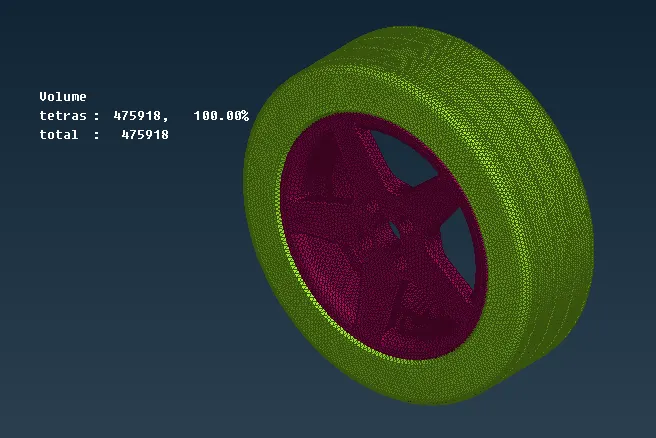
Fig. 23 3D Meshed Model.
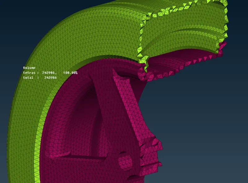
Fig, 24 Cross Section – Volume Meshed Model.
Quality Checks on the volume Mesh: After the volume mesh has been created, it has to be checked for the quality issue namely Tet Collapse. Figure 25 shows the volume meshed model is free from any given quality criteria.
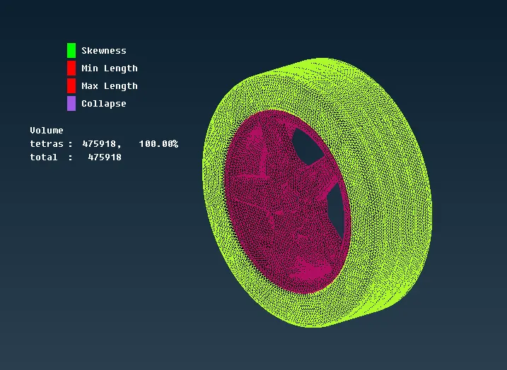
Fig. 25 Volume Quality Criteria checked.
Mesh Release: After the quality checks, the mesh elements were released from the geometry.
2. Other Non-Uniform Thickness Parts:
Surface Meshing: For Volume mesh, meshing has been carried out on the surface of the other parts having non-uniform thickness with the following mesh parameters shown in figure 26.
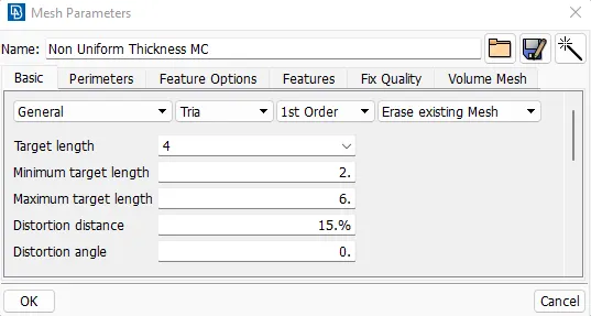
Fig. 26 Mesh Parameters.
Figure 27 shows the mesh created on the surface.
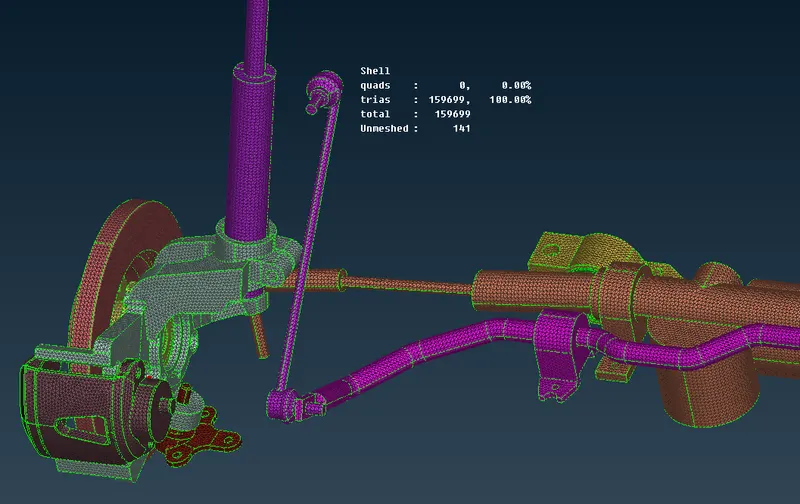
Fig. 27 Surface Meshed.
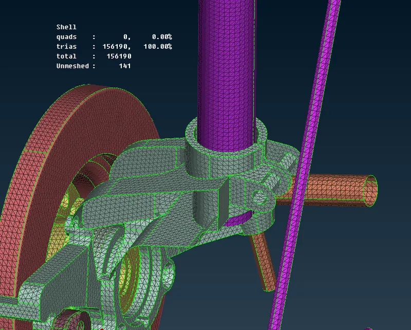
Fig. 28 Cross Section - Surface Meshed.
Surface Mesh Quality Checks: After surface meshing, quality checks have to be performed and the mesh should be free from quality errors. Figure 29 shows the Quality Criteria set for the given model.
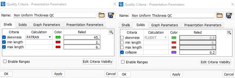
Fig.29 Quality Criteria Check.
The quality check was performed and quality errors were cleared. The mesh model free from quality error is shown the figure 30.
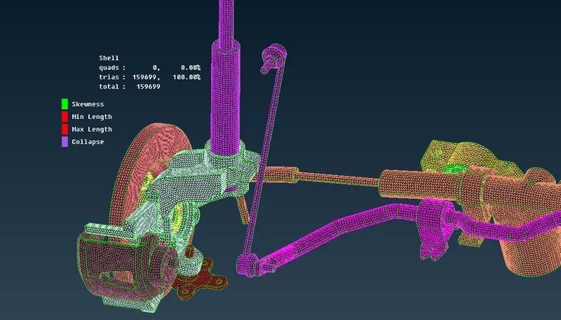
Fig. 30 Quality Checks performed on the mesh.
Assigning Volume PID: After clearing all the quality issues on the surface mesh, the volume has to be created for generating 3D mesh. So each component of the model has been declared as closed volume and separate PIDS were assigned as shown in figure 31.
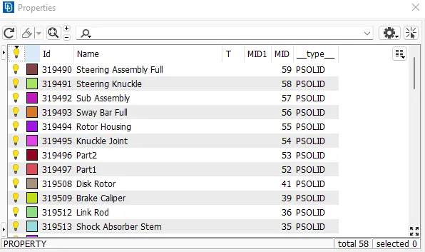
Fig. 31 Volume and PIDs assigned for each Component.
Surface To Volume Mesh Generation: After declaring closed volume, the Unstructured Mesh type is used. Under the Unstructured mesh tab, Tetra FEM or Tetra Rapid type of meshing can be selected. In this model, the Tetra FEM type meshing algorithm is used and 3D mesh is generated. Figures 32, 33 & 34 show the meshing algorithm type, 3D meshed model, and cross-section of the volume mesh.
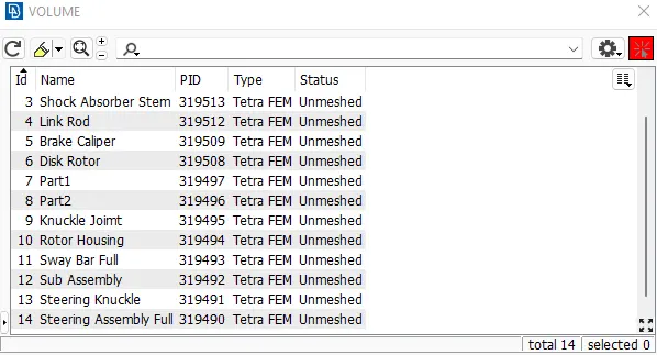
Fig. 32 3D Meshing Algorithm type.
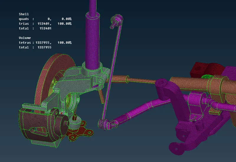
Fig. 33 3D Meshed Model.
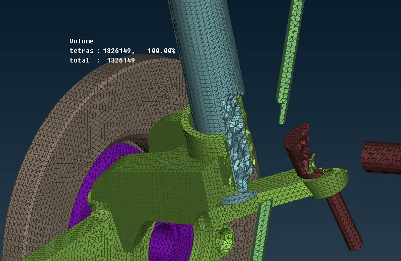
Fig, 34 Cross Section – Volume Meshed Model.
Quality Checks on the volume Mesh: After the volume mesh has been created, it has to be checked for the quality issue namely Tet Collapse. Figure 35 shows the volume meshed model is free from any given quality criteria.
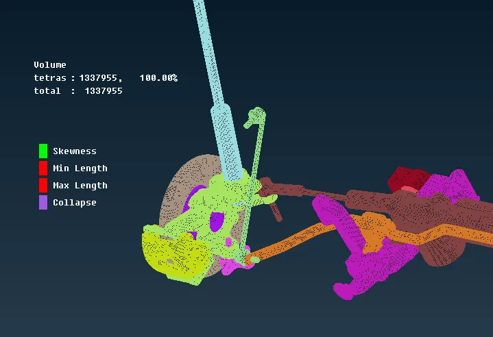
Fig. 35 Volume Quality Criteria checked.
Mesh Release: After the quality checks, the mesh elements were released from the geometry.
III. Spring Element: The spring element is represented as 1D elements for straightforward representation. The following steps are followed for defining spring as the 1D element. 1. Middle Curve or Centre Line for the spring is obtained. Figure 36 shows the center line obtained for the spring.
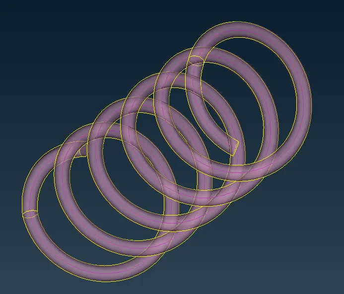
Fig. 36 Centre Line of the Spring.
Then it is converted to CBAR type to represent the spring element by using the options available under the NASTRAN deck-ELEMENTS-CBAR-CURVE(BOX). Then the radius of the spring element is provided such that the area is calculated by ANSA itself. Figure 37 shows the spring represented as CBAR elements in 1D. Later the Line is drawn as solid to represent the spring as in the original CAD geometry. Figure 38 shows the spring model in the real environment.
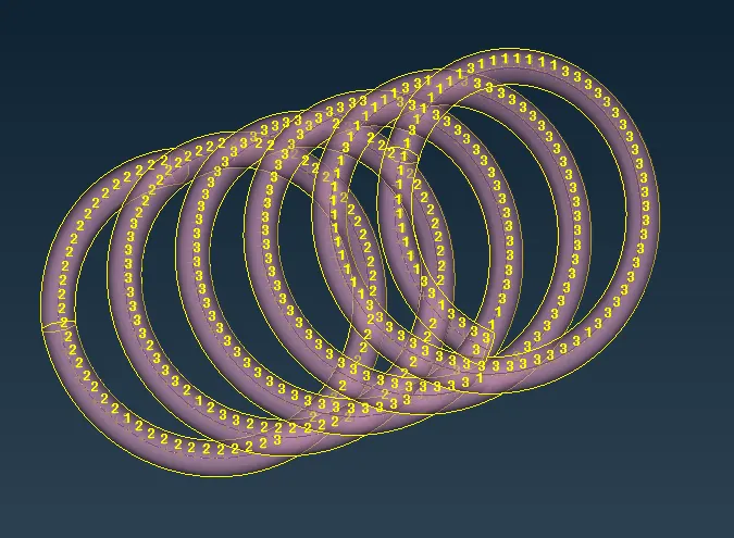
Fig. 37 Spring is represented as a CBAR 1D element.
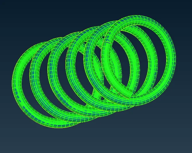
Fig. 38 Spring Line is drawn as Solid.
IV. Symmetry Plane: Since the given assembly model is symmetrical, the meshed part has been mirrored and pasted to the already mesh parts. For that, first, the meshed parts were copied by using the TRANSFORM-COPY-SYMMETRY-MIRROR 3 POINT PLANE option was used. Figure 39 & 40 shows the before and after mirror option used.
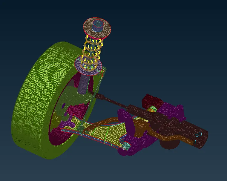
Fig. 39 Before mirror Operation.
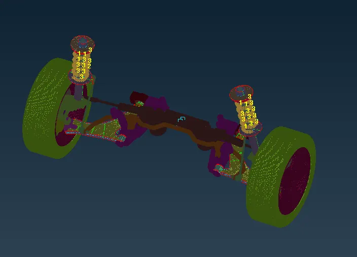
Fig. 40 After mirror operation.
V. Connections:
RBE2 Connections: The RBE2 elements were used where holes or provisions were provided so that the surfaces can be bolted or joined together rigidly. RBE2 is used for providing rigid connection to the surfaces, such that it arrests all 6 DOF.
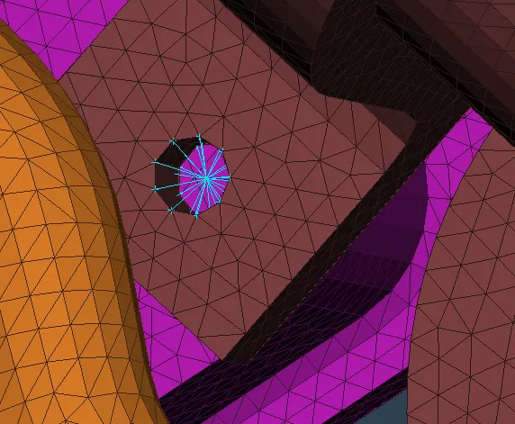
Fig. 41 RBE2 element used for connecting three surfaces.
Figure 41 shows that RBE2 elements were used for connections because it has hole provision, which allows us to rigidly connect the two parts.
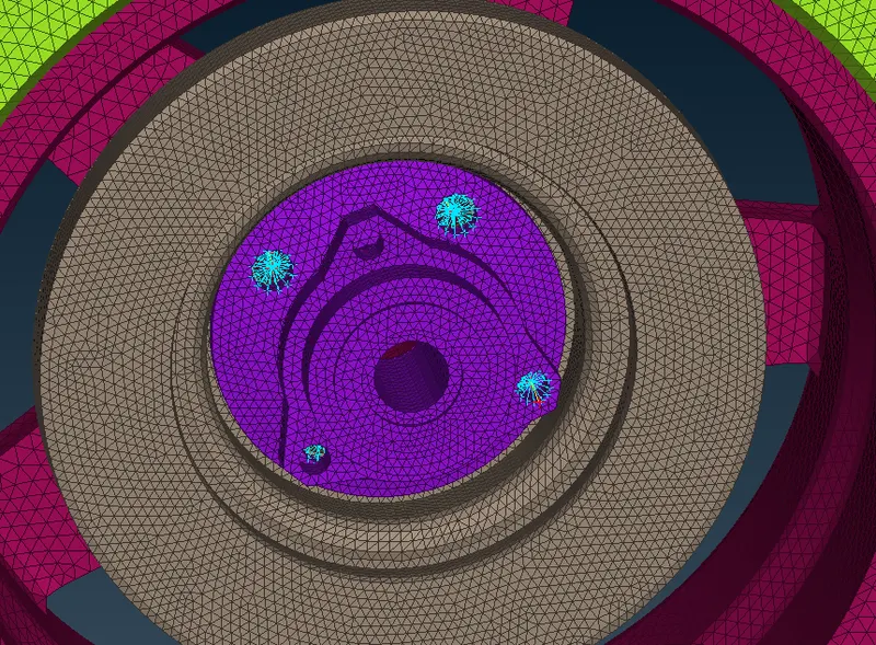
Fig. 42 Two Node RBE2 Connection.
There are two ways to provide rigid RBE2 connections. One uses Two Node RBE2 and the other Many Node RBE2. Figure 42 show Two Node RBE2 connection where two holes have separate RBE2 elements in blue color with Two Node RBE2 element in Yellow color. In this type, each hole has a separate Master Node and the Master Nodes of each hole are connected later. The two blue RBE2 elements were constrained rigidly by the Single Yellow line RBE2 element. Figure 43 shows Many Node RBE2 or Cluster RBE2 connections. In this type of connection both the holes are connected by a single Master Node. It looks like a cluster of flower petals, the so-called Cluster type or Many Node RBE2 connection.
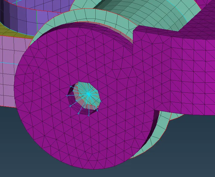
Fig. 43 Cluster or Many Node RBE2 Connection.
Figure 44 shows the entire connections provide to the assembly model.
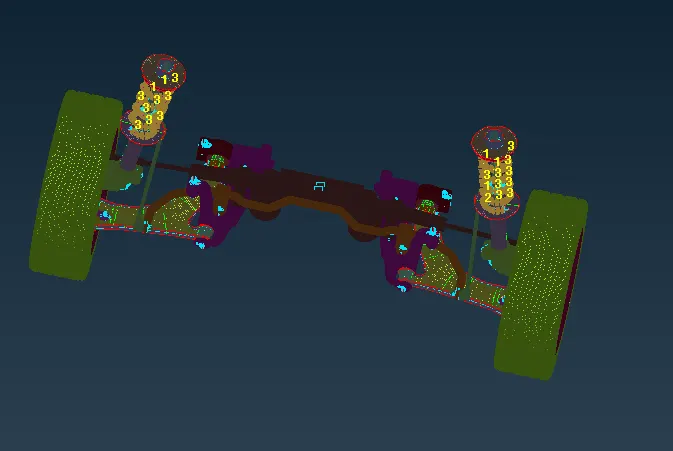
Fig. 44 Connections provide to the entire assembly.
LEARNING OUTCOMES:
- Mid Surface Extraction for any complicated geometry.
- Meshing of complex structure/components by splitting into many parts/cut portions.
- Assigning appropriate thickness for each component.
- Surface Tetra Mesh for any complicated geometry.
- Easy meshing with different Ortho Tria and Tria mesh options.
- Good ortho tria mesh flows around any openings or holes to capture it neatly.
- Assigning appropriate closed volume for 3D mesh Generation of each component.
- Providing rigid to places where it is required.
- Assigning an appropriate Degree Of Freedom for the rigid elements to constrain their motion.
CONCLUSION:
Mid Surface Extraction for any complicated geometry by splitting into many parts. Meshing of complex structure/components by providing cut at require/desired area to capture perfectly. Assigning appropriate thickness for each component. For volume mesh, easy meshing with different Ortho Tria and Tria mesh options. Good ortho tria mesh flows around any openings or holes to capture it neatly. Assigning appropriate closed volume for 3D mesh Generation of each component. Providing rigid to places where it is required. Assigning an appropriate Degree Of Freedom for the rigid elements to constrain their motion. Finally represents spring with the help of CBAR as 1D elements.