Project - 2 - Meshing on the suspension Assembly
Aim:
The given assembly, check for the geometrical errors and mesh with the given element Quality criteria. After meshing the component the thickness has to be assigned for mid surfaces.Use tetra elements to model non-uniform thickness components. Also use Appropriate connections to connect the component.
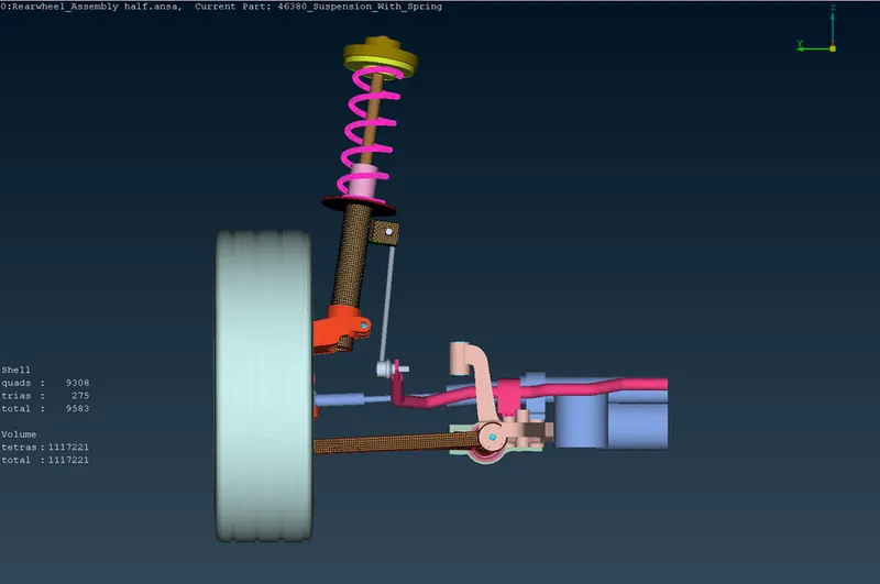
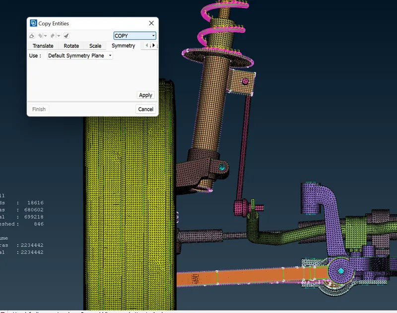
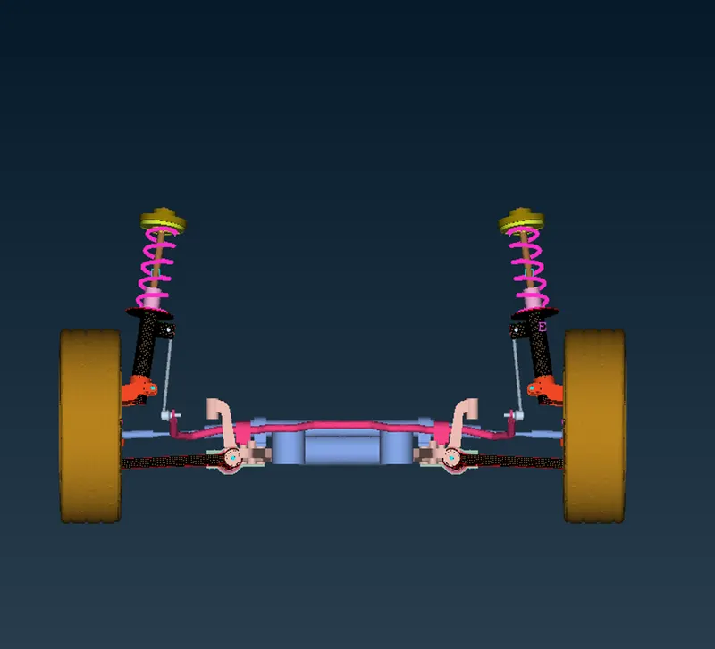
At last perform Symmetry command to reflect the half finished model to the other side.
Given Quality Criteria:
Quality Criteria for Surface Meshing of Tyre and Rim (Element type: Tria) :
|
S.No |
Quality Criteria |
Value |
|
1 |
Target/Average length |
6.5 |
|
2 |
Minimum Length |
5 |
|
3 |
Maximum Length |
10 |
|
4 |
Skewness |
45 |
Quality criteria for Surface Meshing of Non Uniform thickness components other than Tyre and Rim (Element type: Tria) :
|
S.No |
Quality Criteria |
Value |
|
1 |
Target/Average length |
4 |
|
2 |
Minimum Length |
2 |
|
3 |
Maximum Length |
6 |
|
4 |
Skewness |
45 |
Quality Criteria for Volume meshing of all Non Uniform thickness components (Element type: Tetra Elements):
|
S.No |
Quality Criteria |
Value |
|
1 |
Tet-collapse |
0.2 |
Quality criteria for Mid surfacing of Uniform thickness part which has thickness less than 5 mm (Element type: Mixed elements) :
|
S.No |
Quality Criteria |
Value |
|
1 |
Target/Average length |
4 |
|
2 |
Minimum Length |
2 |
|
3 |
Maximum Length |
6 |
|
4 |
Aspect |
3 |
|
5 |
Warpage |
15 |
|
6 |
Skewness |
45 |
|
7 |
Jacobian |
0.7 |
|
8 |
Minimum Quad Angle |
45 |
|
9 |
Maximum Quad Angle |
135 |
|
10 |
Minimum Tria Angle |
30 |
|
11 |
Maximum Tria Angle |
120 |
Procedure:
1. Import the given model.
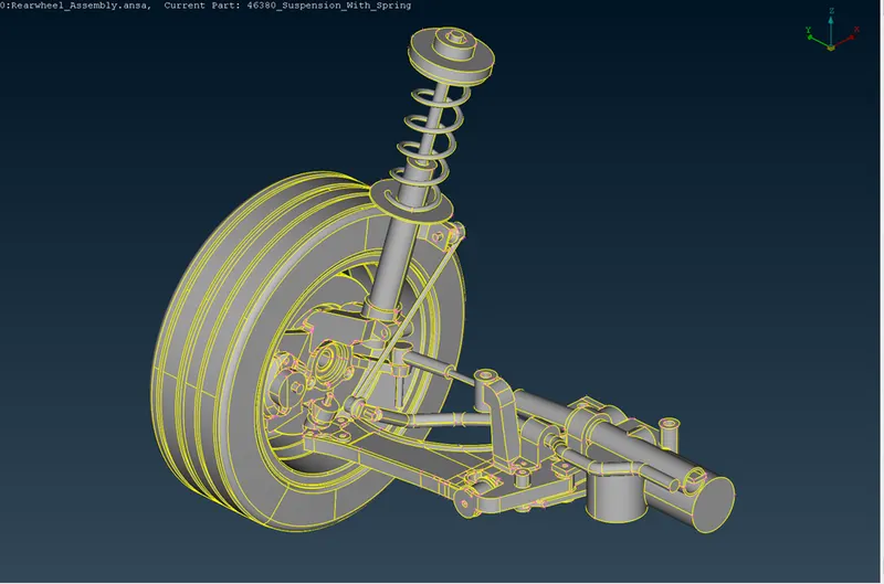
- Perform the topology in the given model.
3. check the geometrical errors and fix them.
{Tool>>Checks>>Geometry>>Execute}
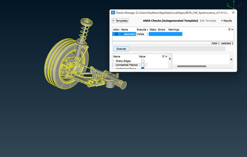
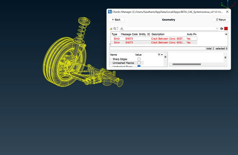
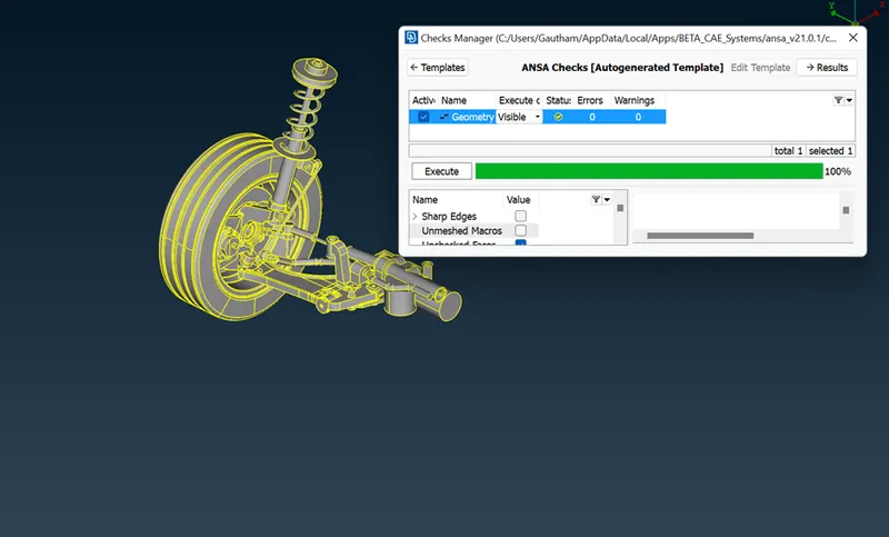
Green tick in status bar shows all the geometrical errors are fix.
4. Now, take mid-surface by using offset or casting methods and set PID simultaneously.
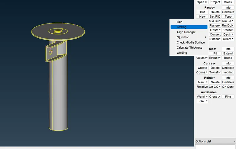
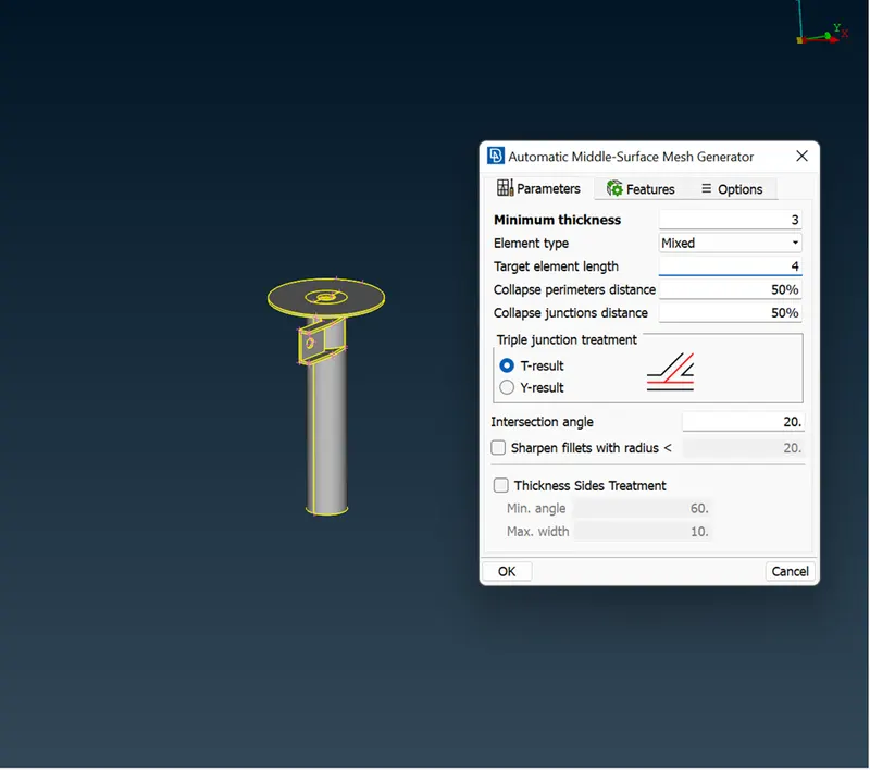
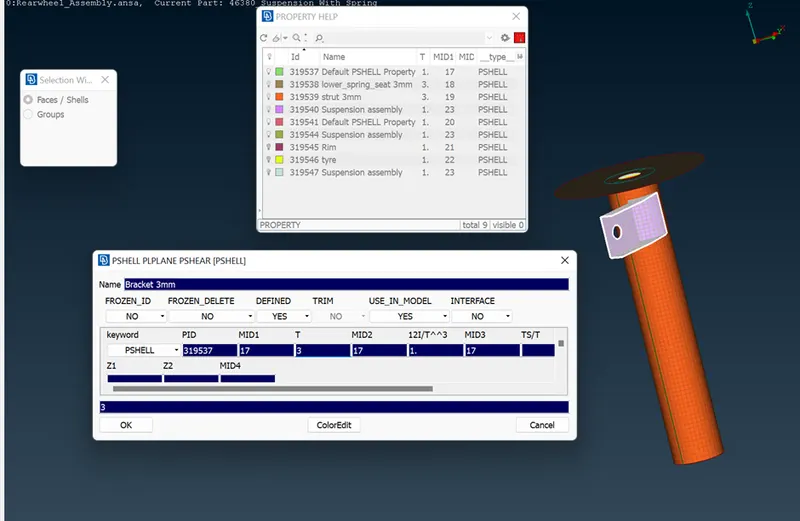
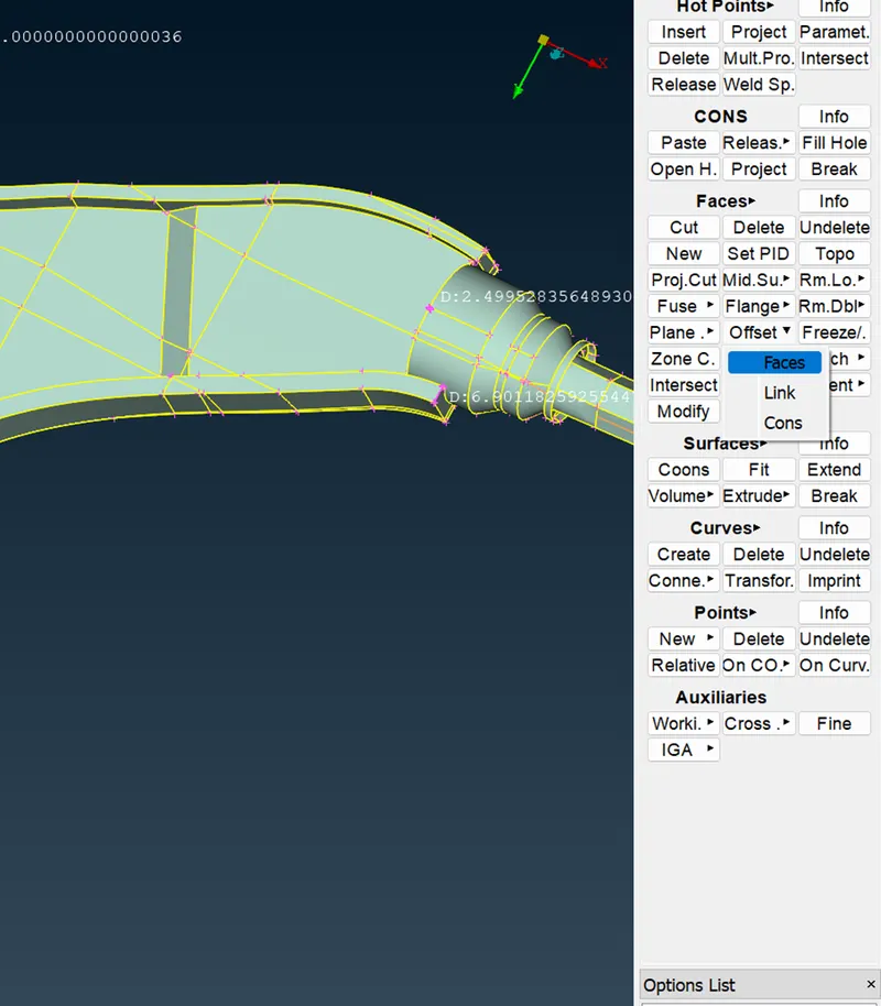
5. The component is use for taking mid suface by the offset method. And make the good mesh flow on the component.
Topo>>Offset>>Faces>>Select the faces and click middle button.
Meshing>>Mesh Generation>>Best Mesh>>Select the face and click middle button.
Before set the quality criteria for the meshing component.
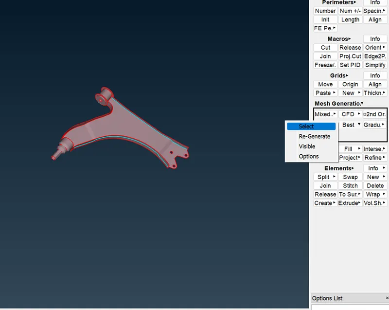
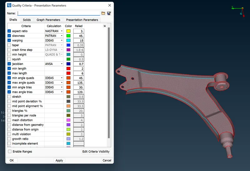
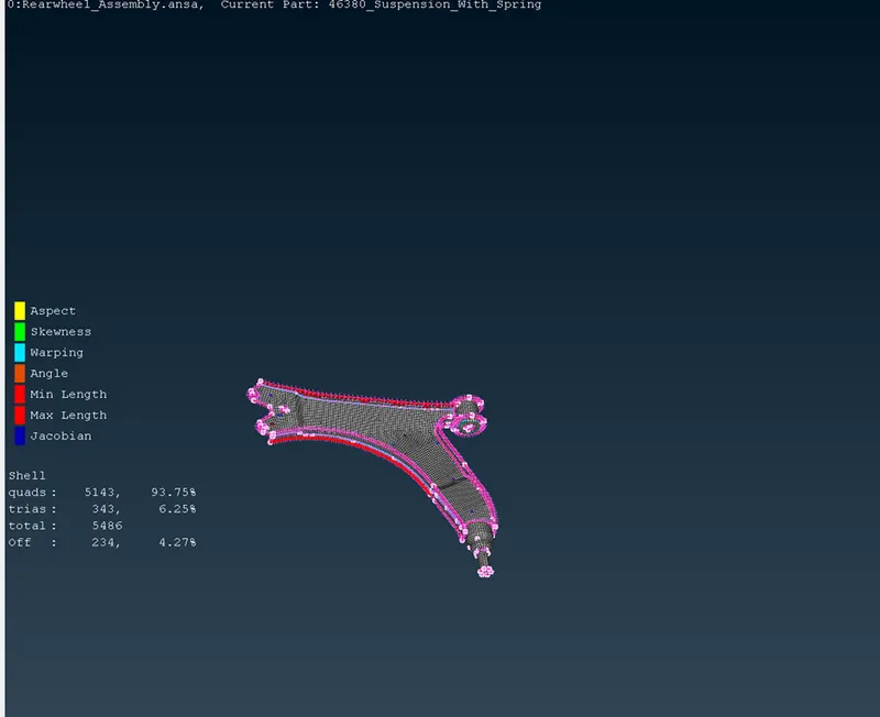
Fix the off elements and make good mesh flow.
6. For the spring component , we represent in 1D CBAR element.
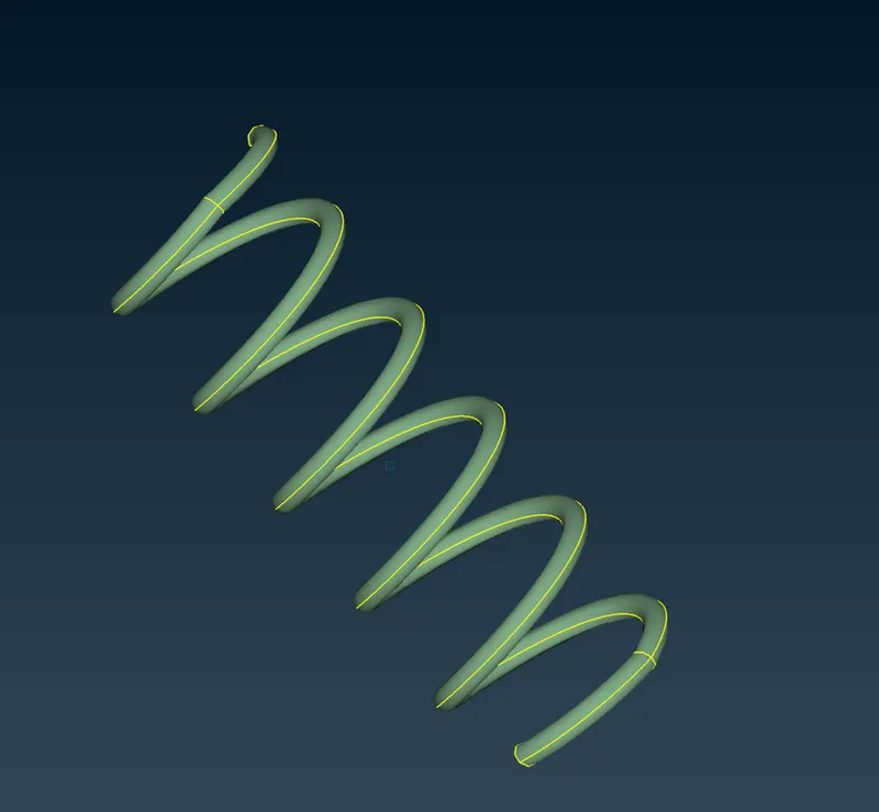
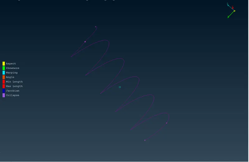
Here the middle curve is generated for the coil spring and create the COG point for the curve to define the orientation.
NASTRAN>>CBAR>>
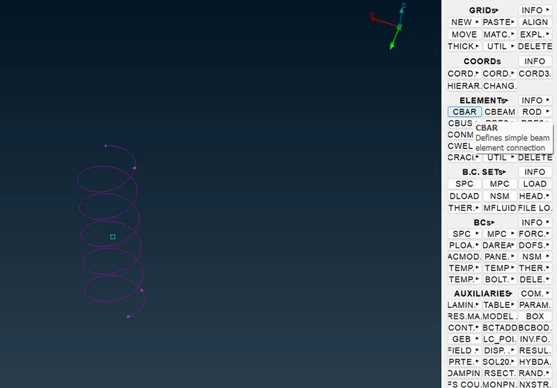
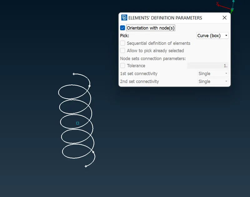
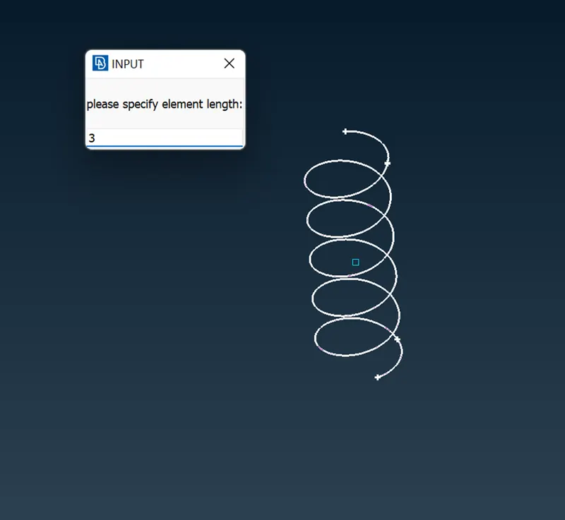
specify the element lenght as 3mm. After middle click of the mouse Set PID for the CBAR element.
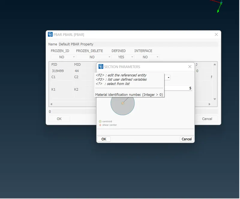
Here the radius is define as 5mm for the coil spring. It will calculate the cross sectional area and moment of inertia.
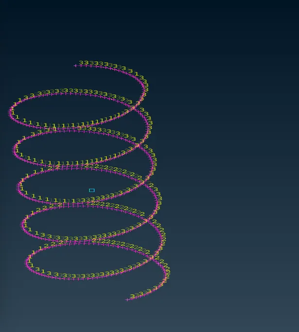
The 1D BAR elements will be created.
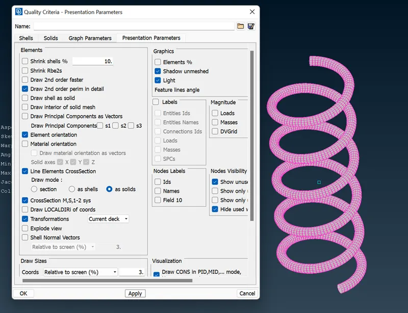
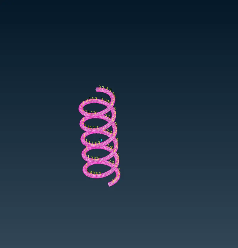
To see the representation of 1D bar elements as 3D Solid, check the box od 1D detailed representation with solid in quality parameters as shown in the below image.
7. Mesh the Tyre & Rim with quality criteria. Use element type tria.
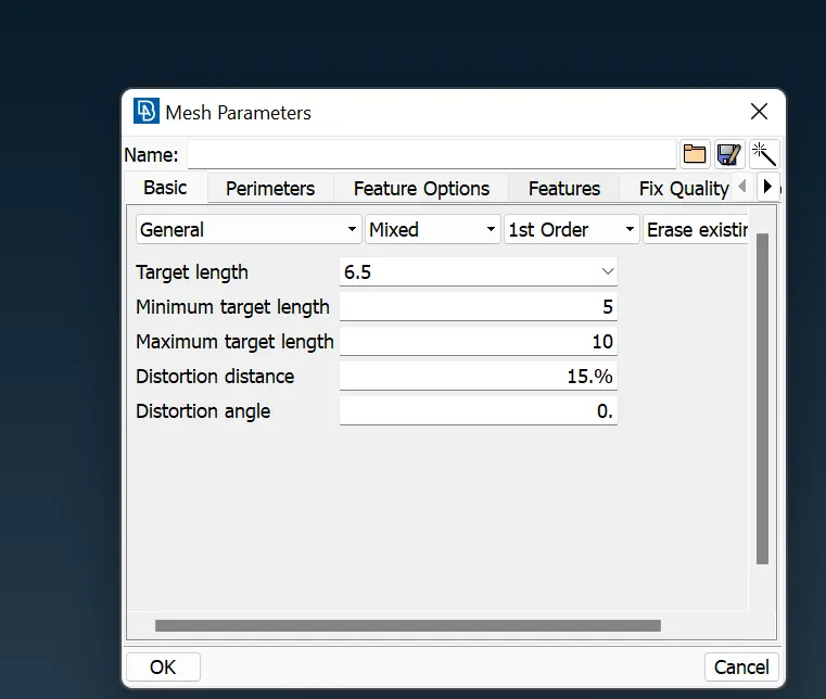
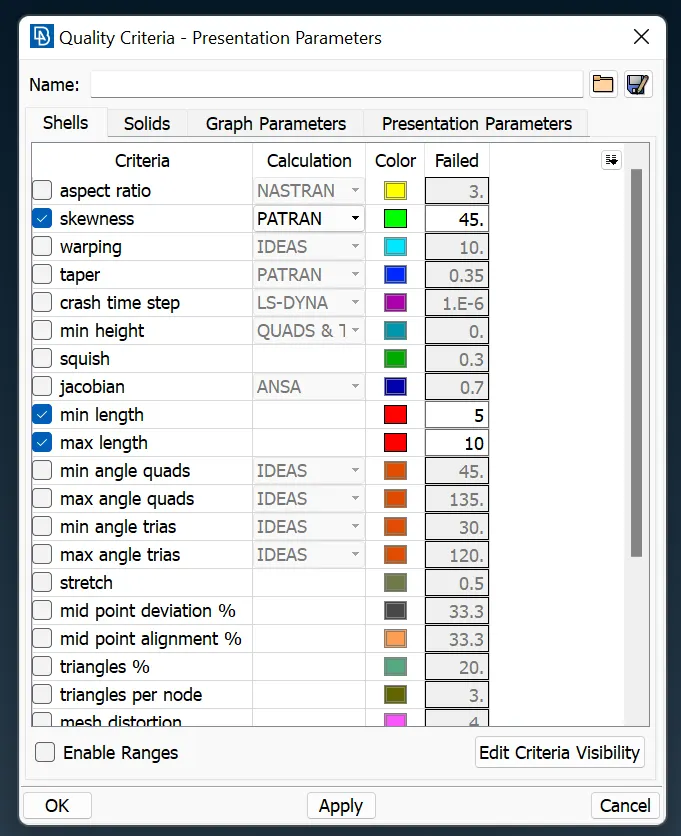
Meshing>>Mesh Generation>>Spot Mesh>>Select the faces and click middle button in the mouse.
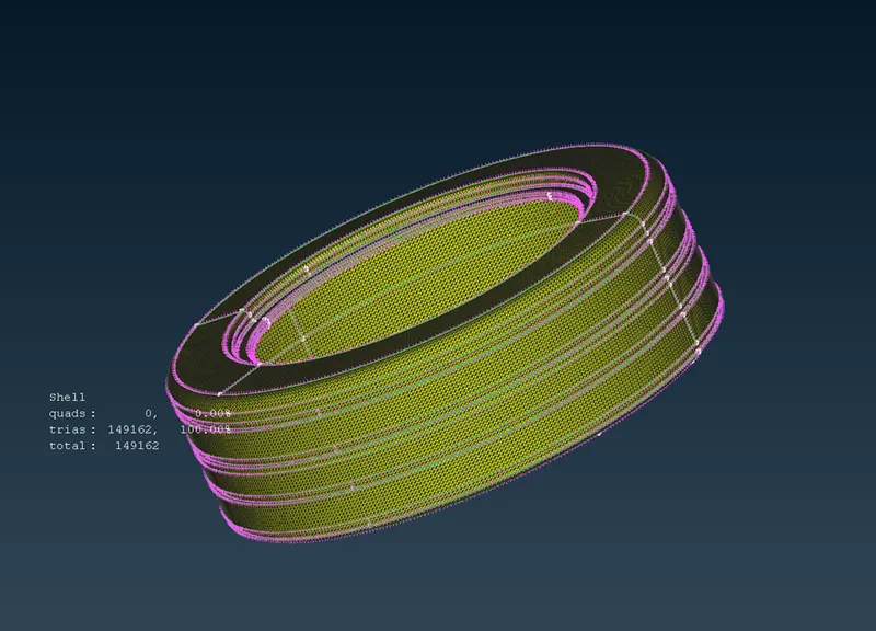
After the meshing the volume is defined.
Volume Mesh>>Volume>>Define>>Select>>select the face and click middle button.
Goto Volume>>List>> the volume is created. Double click on that and select mesh type and click ok.
and right click on the PID and Make remesh. The soild mesh is done.
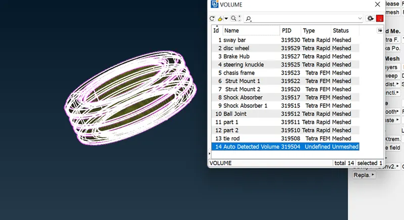
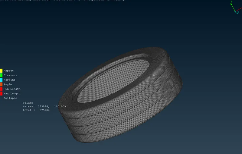
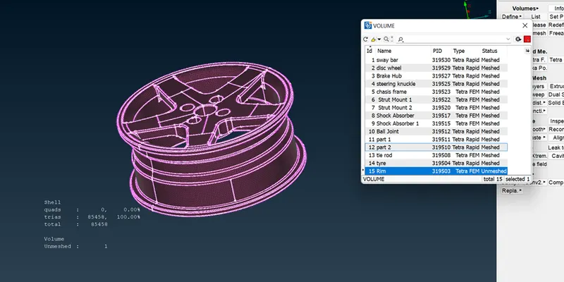
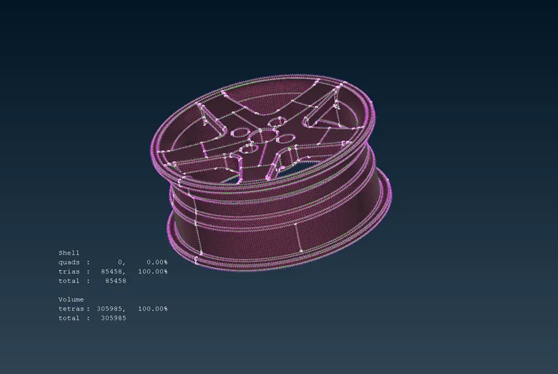
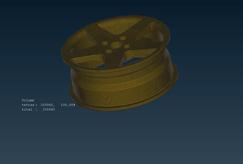
Here the volume mesh is done for the Rim component.
7. Make the solid volume mesh for the following components a steps followed for the tyre and rim but the quality criteria is changed for these components.
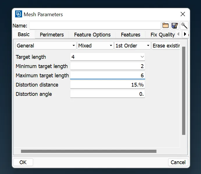
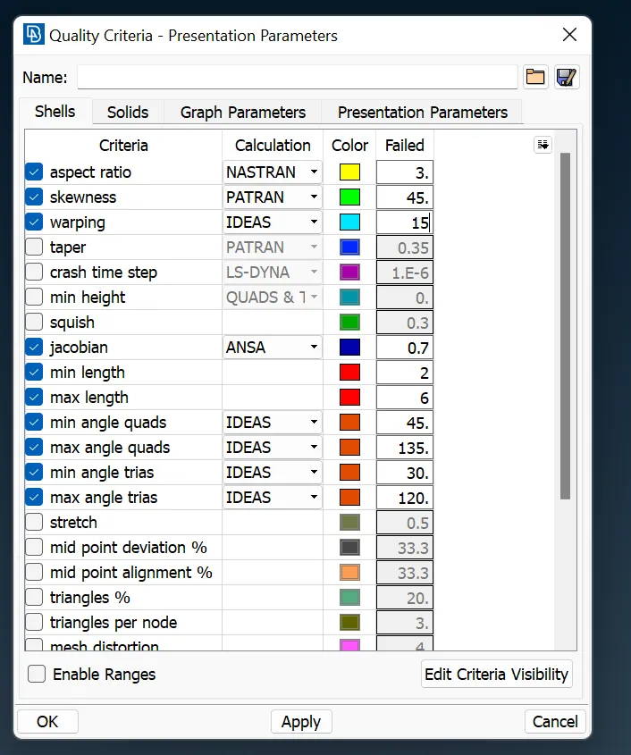
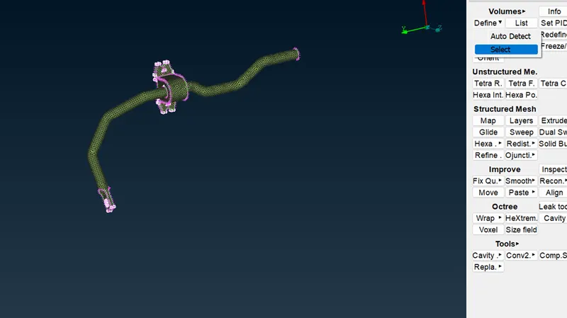
Here the volume is defined.
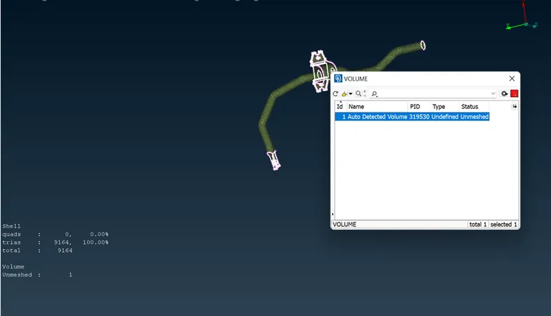
The volume PID is Generated.
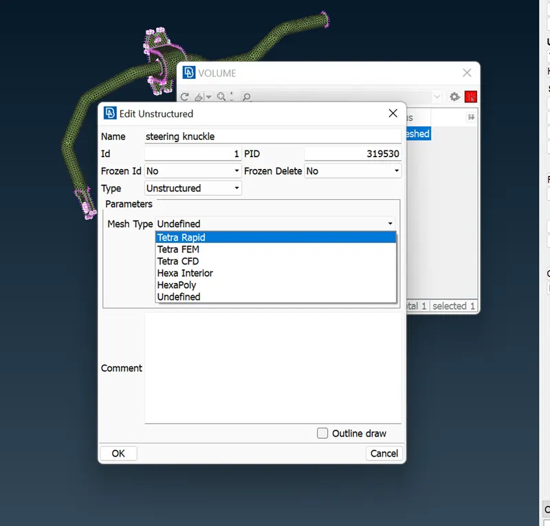
Here we selecting the mesh type.
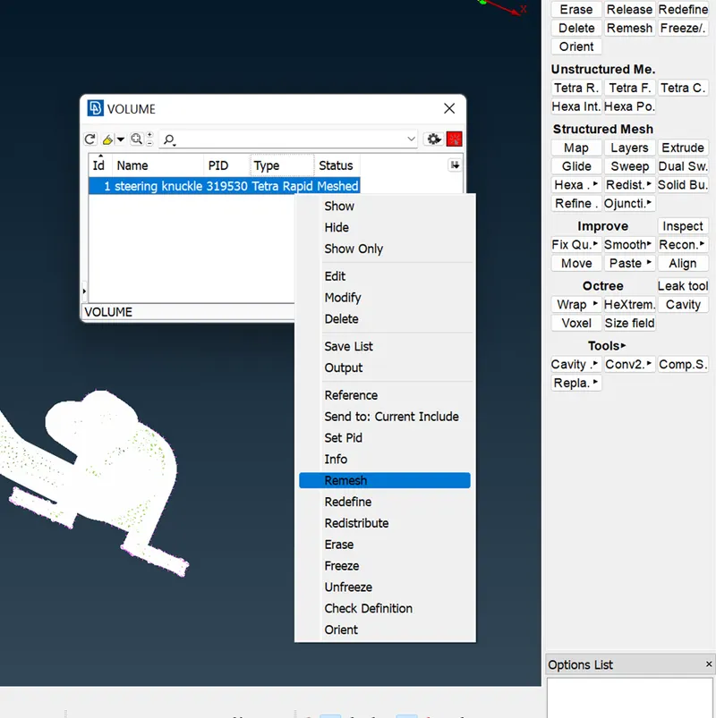
Here we meshing the volume by remesh option.
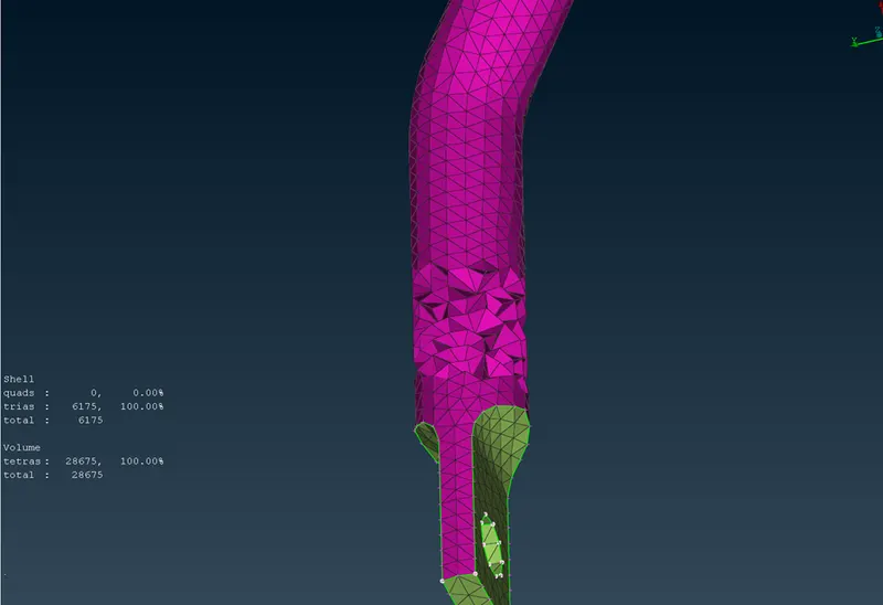
Here the solid mesh is done.
The same steps are followed for following components.
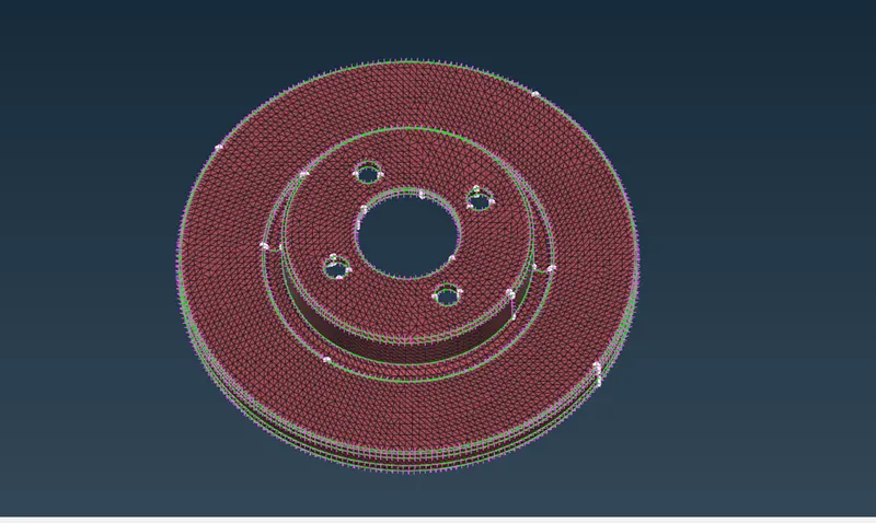
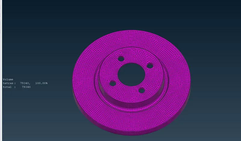
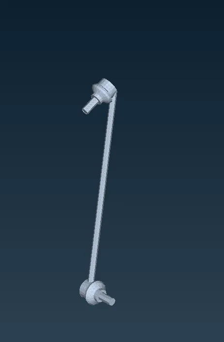
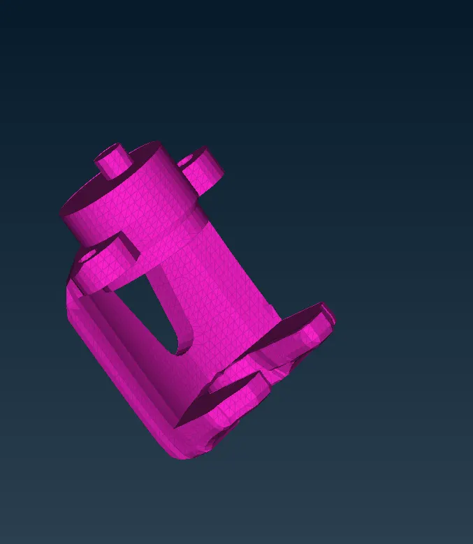
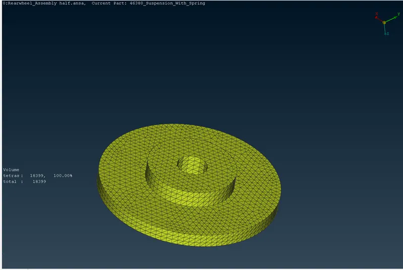
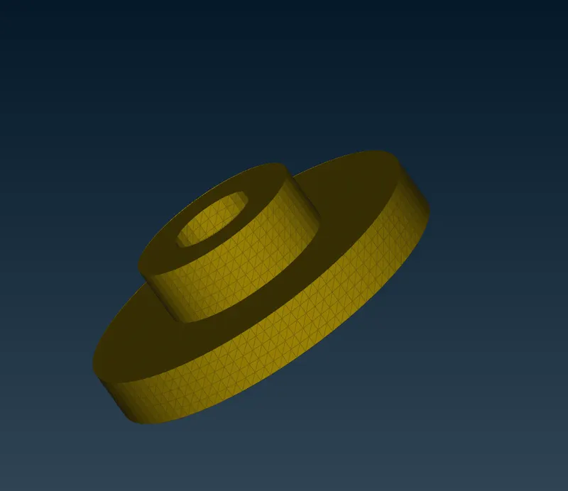
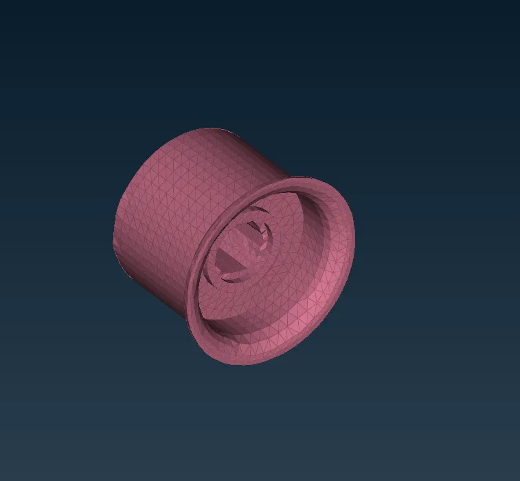
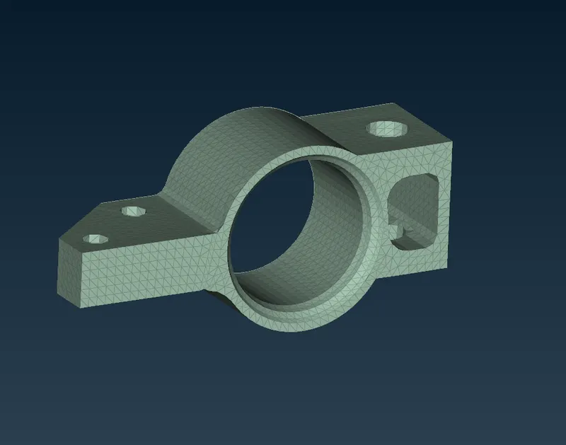
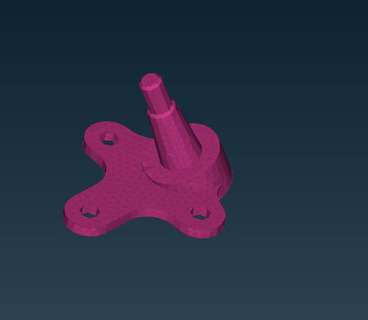
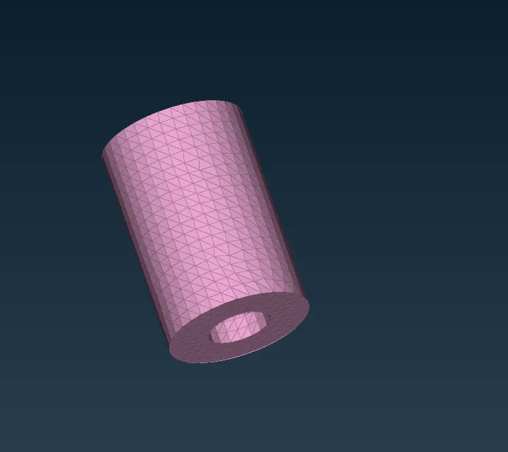
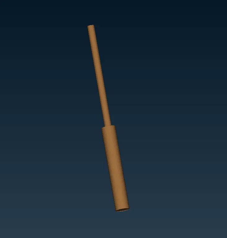
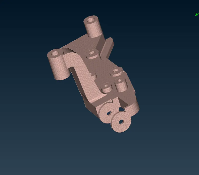
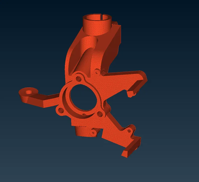
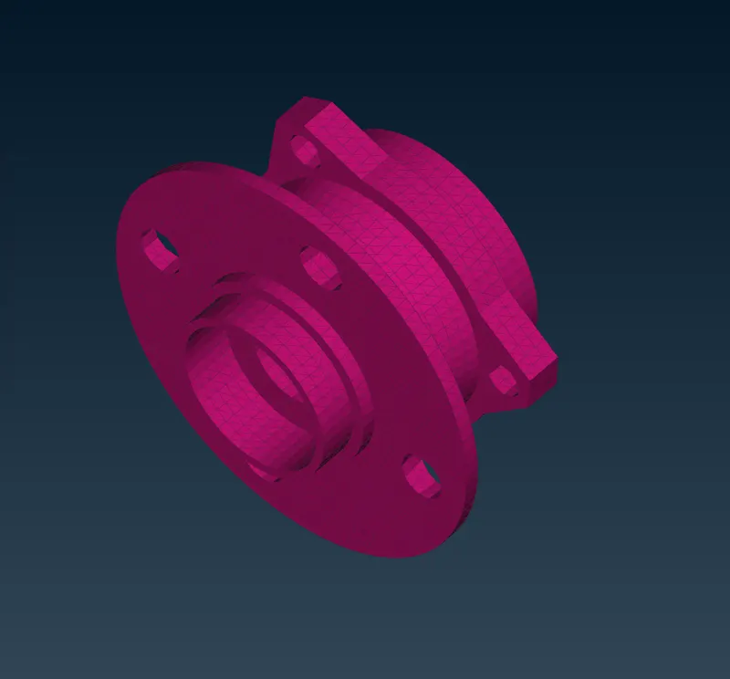
The following all components the volume is defined and volume meshing has been done as per the given quality criteria.
Connection:
8. weld:
The over laping weld is done for these components.
Topo>>Curves>>Cons2curve>> select the con and make as the curve.
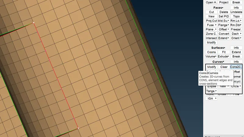
By the convertion convert the curve into seam line.
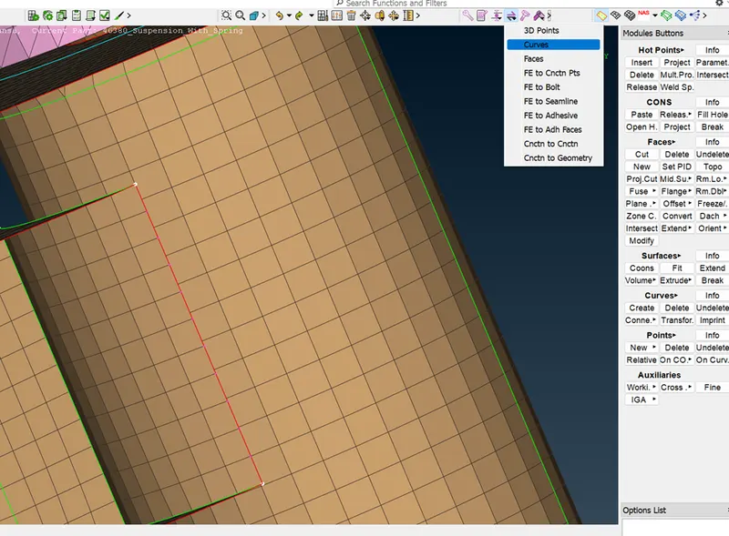
Goto the connection manager and select the seam line and define the connection as overlaping weld.
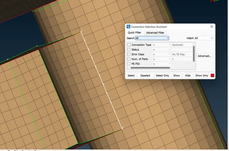
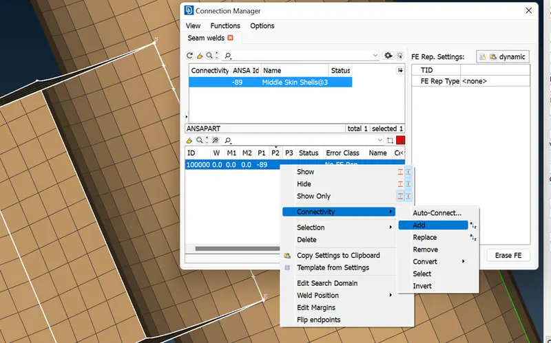

Here the weld is created.
9.RBE2 connection:
I used RBE2 connection for both bolt and rigid cluster element.
Nastran deck > Elements >RBE2 > many nodes or Two nodes > select the nodes and middle click.
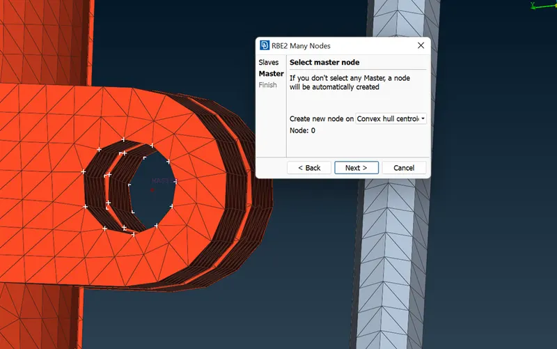
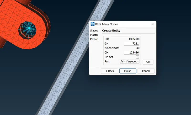
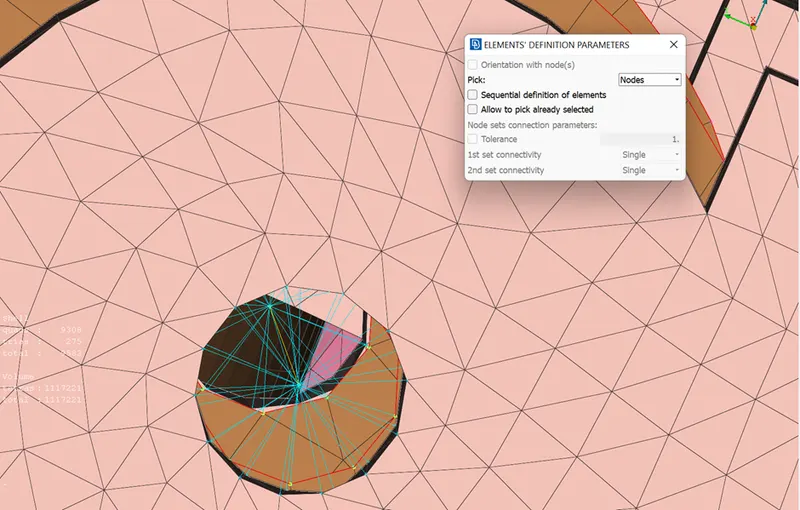
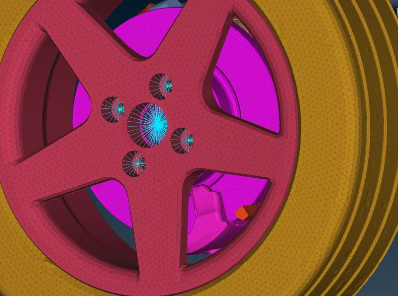
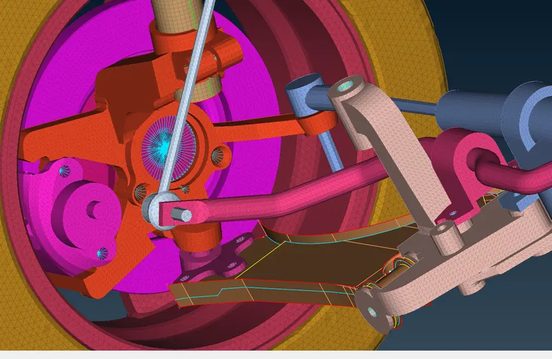
After the all the connection were done make symmetry.
10. Goto Transform>>copy>>select entities>>middle click>>symmetry>>Use Mirror 3 point plane>>select 3 points and apply>> finished.
Learning Out Comes:
1. Learn about volume meshing.
2. Learn about how to model suspension spring.
3.Learned creating 1D elements for spring
4. Learn about how to reflect model to the other side.
5. Determine and deploying all connections according to its applications.
6. Understand the concept of Transform and Symmetry in this project.
Conclusion:
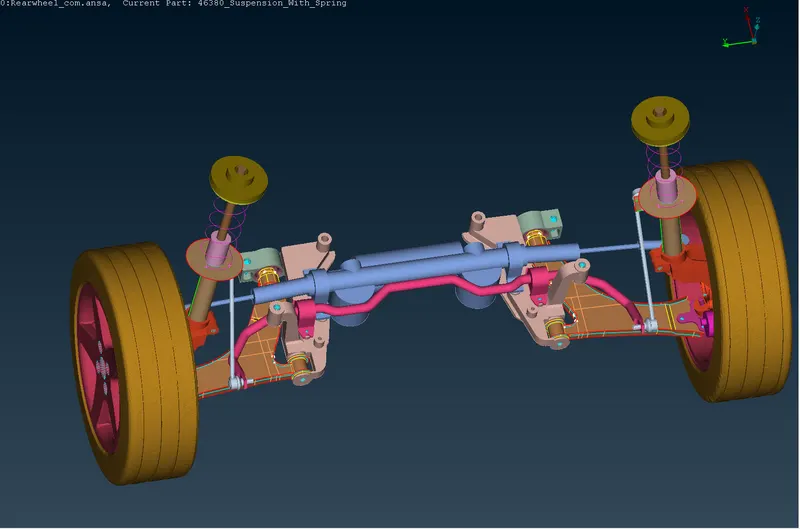
In this rear suspension assembly, we have finally achieved a good surface and volume
mesh flow, by resolving all geometrical errors along with
Topology cleanup and by satisfying given quality criteria for shell and solid as per
mentioned requirement. And also we have deployed connections as per requirement
namely RBE2 and CBAR connections. Finally the give suspension assembly is modelled as per given quality criteria.
Link for the Rear suspension Ansa File:
https://drive.google.com/file/d/1DeVL8vTOzB6rdCik0Ahk0445nRmfgl9T/view?usp=sharing