Project - 2 - Meshing on the suspension Assembly
Meshing on Rear Suspension Assembly
Aim: For the given assembly, check for the geometrical errors and mesh with the given element Quality criteria. Also, use Appropriate connections to connect the components.
Procedure:
1. Geometry Cleanup:
In the given assembly there are many uniform and non-uniform thickness components. For uniform thickness( <5mm) components we need to do 2D mesh and for above 5mm thickness components we need to do 3D mesh. Open each component and check any geometrical errors present like single cons or broken surfaces. In some components, ANSA showed concave cons, it is just the shape of the geometry and we can ignore it.
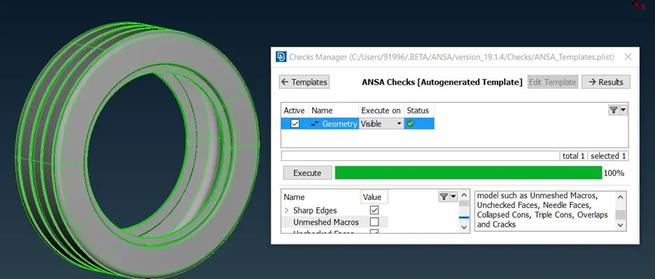
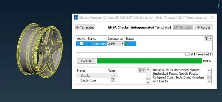
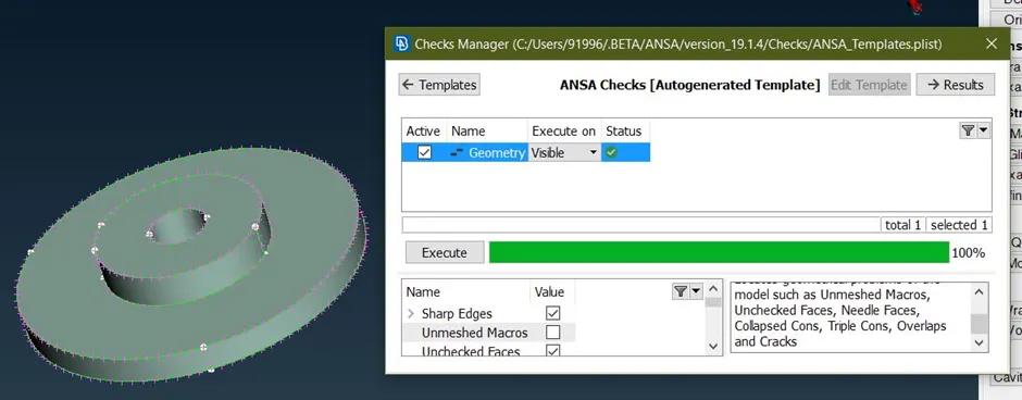
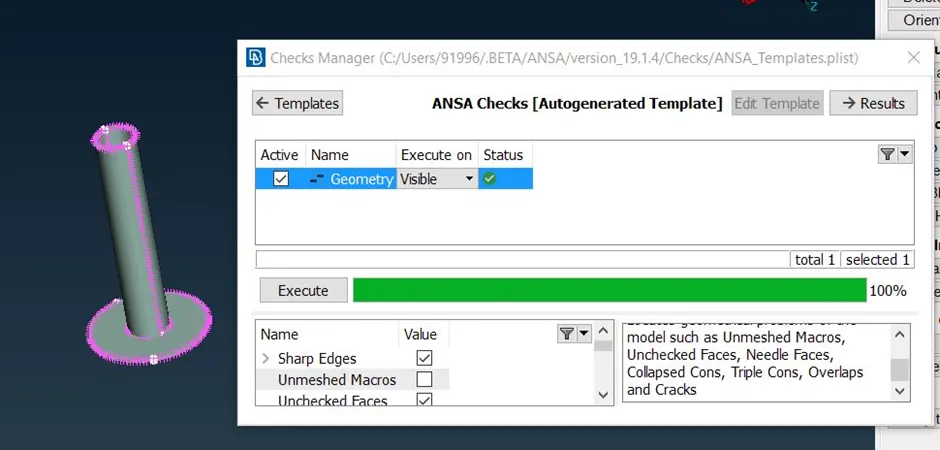
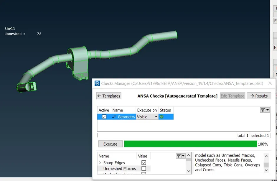
Fig 1: Geometry check-up of some components
1D Mesh: Spring is like an axisymmetric component so, we can mesh it using 1D elements. So, I have obtained the meshing of spring using 1D elements. I have created a mid curve of spring using the two cons present on the spring outer diameter. (Topo > curves >middle) Then make it a single curve using multi-option in curves. Then created a 3D point using On COG option to define orientation. Then Nastran deck > Elements > CBAR > select the middle curve of spring. Then for the orientation select the above-created point and give the element length as 4mm and after the middle-click, it will ask PID. In the PID window to define area use shift+?
Give the radius of the spring, it will calculate the area and moment of inertia of the spring.
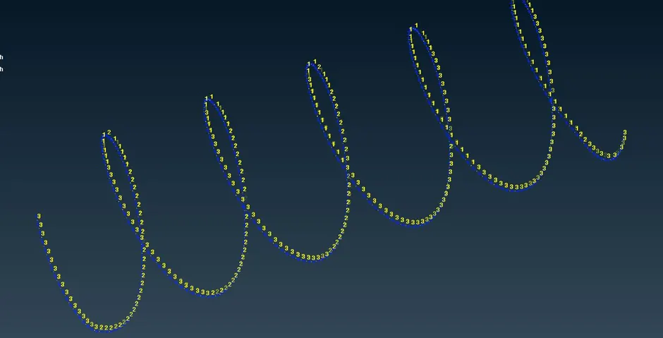
Fig 2: 1D CBAR element of spring
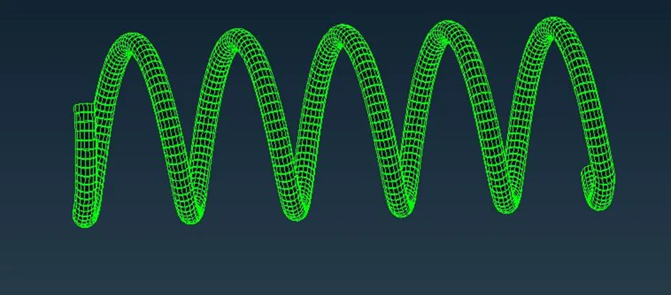
Fig 3: Spring elements after checking the thickness
2D Mesh: For components below 5mm thickness we need to do 2D mesh, to create less no. of elements and save solving time. I have done 2D mesh using the Casting option. Because it is a simple surface, instead of taking mid and mesh that mid, to save time I used the casting option. I have taken quality and mesh parameters as given in the assignment for mid-surface. Use reconstruct , move free, and smooth, etc. options to get the good mesh.
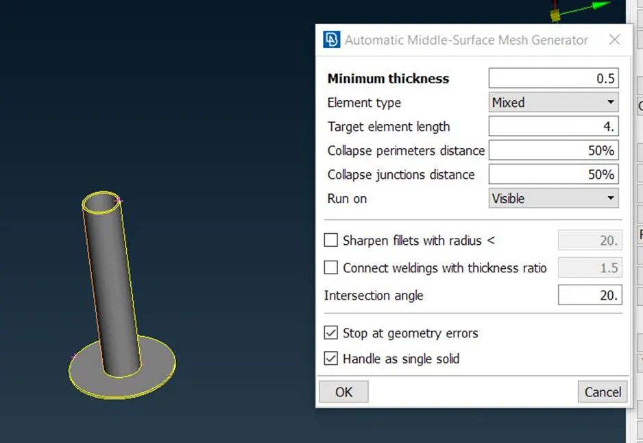
Fig 4: Taking Mid FE using Casting
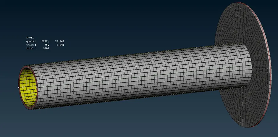
Fig 5: After finishing of meshing
3D mesh: Before achieving 3D elements, we have to do surface mesh on the components. That is 2D mesh only on the surface of the component. I have taken the surface mesh criteria for 3D meshes. There are different quality criteria for Tyre and Rim parts. Change in the mesh parameters to ortho tria or tria elements. And do mesh on the surface using spot mesh. For round and curvy surfaces use spot ortho tria mesh, for normal flat surfaces use tria mesh. In some places I have used the tria mesh for round surfaces also to clear the minimum or maximum element criteria. I used MV free option to clear most of the off elements if they are not solved by reconstruct option. On some components, I used the batch mesh option to create surface mesh on the components. But it is creating more off elements, and taking more time to do remesh again. One disadvantage in batch mesh is you can only give one controllability of mesh either ortho tria or tria mesh, anyway it will create both elements to do mesh.
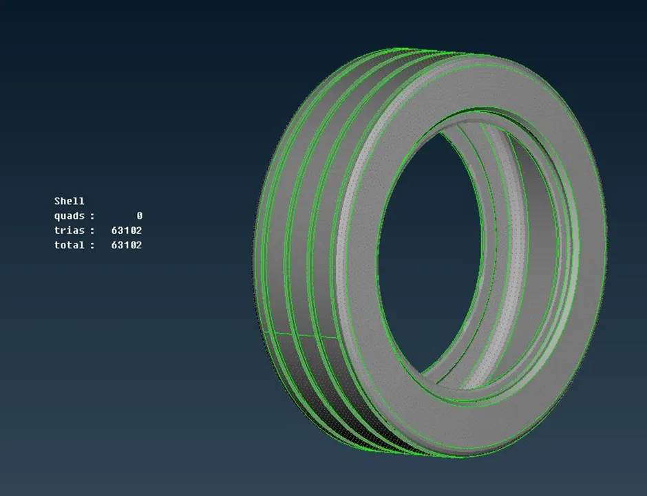
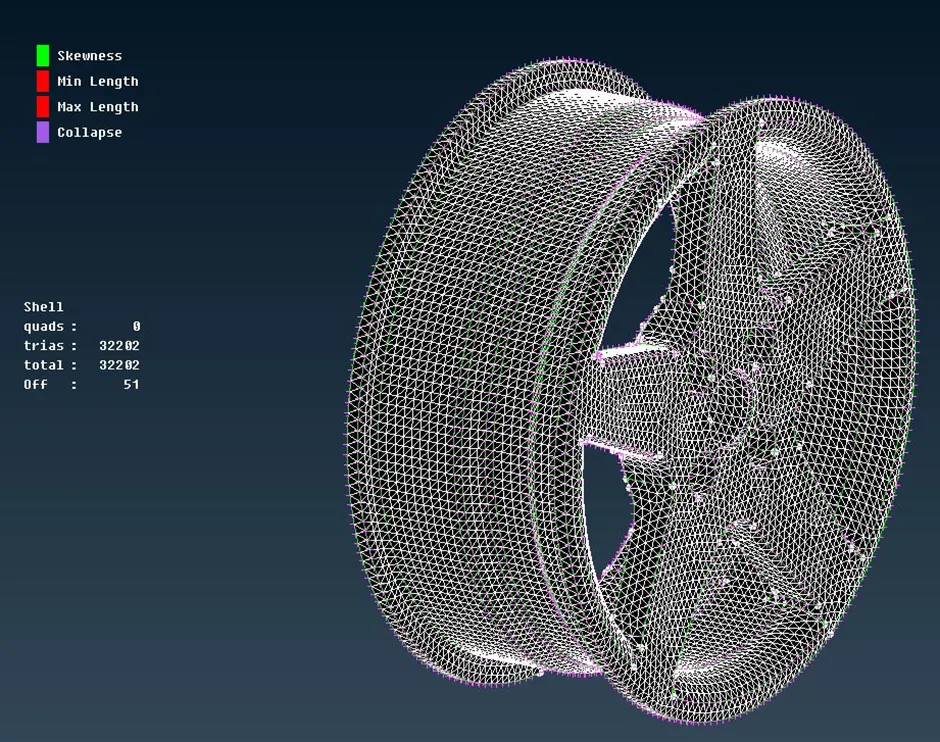
Fig 6: Surface mesh on the components
After the creating surface mesh, go for Volume mesh > Volumes > Define > manual > box selection of the component. In the list menu in the volumes, you can check the created volume. Now we need to mesh that created volume. On the right click of the created volume, it will show options in that select Remesh option and select either Tetra rapid or Tetra FEM method to create tetra elements in the volume. Check for tet collapse criteria (0.2).
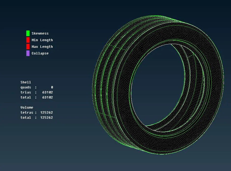
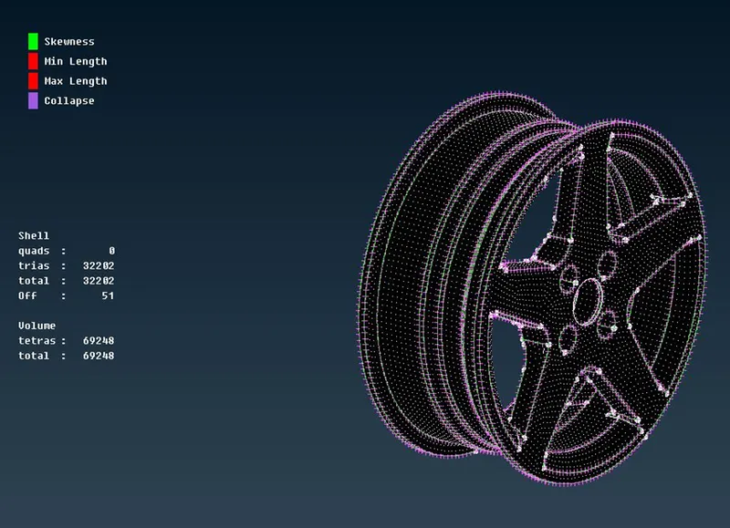
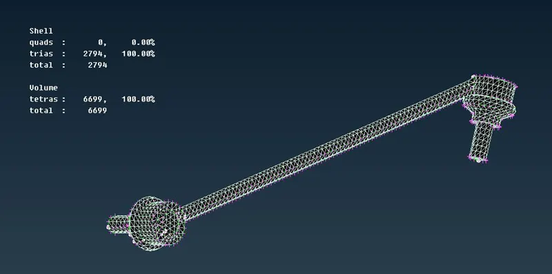
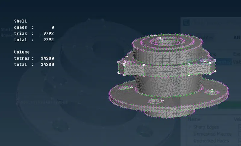
Fig 7: 3D mesh obtained the components
Connections:
- Seam weld connection: To perform seam weld connection, we should create weld curve. And after that to define it as seam weld curve, go to Assembly > Define > curves > select the created curve > select seam weld. To create the seam weld, Assembly > connection manager > select the weld curve > middle click. It will open the connection manager window, in that select the two components as p1 and p2 using F1 key. Select the FE representation as overlap shell for parallel surfaces. Y Joint for perpendicular surfaces. Here I used Overlap shell representation.
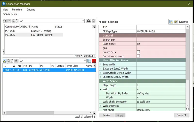
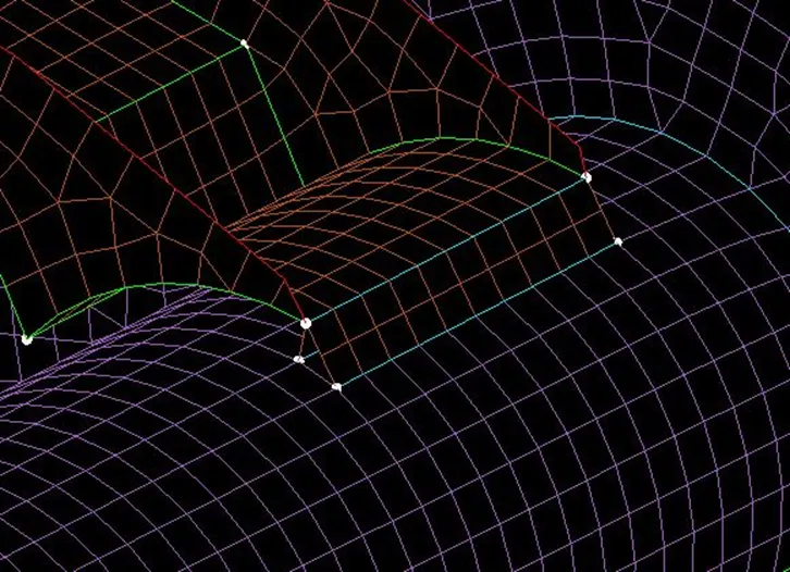
Fig 8: Seam weld connection
- RBE2 connection:
I used RBE2 connection for both bolt and rigid cluster element. Nastran deck > Elements > RBE2 > many nodes or Two nodes > select the nodes and middle click. To create a bolt connection first create a cluster RBE2 element using many node option ( it will create one master node of all the nodes) on the hole of one component. And create a second cluster element on the second component. Then create bolt stem, using RBE2 two-node option select the two master nodes of cluster element. I went for this option to save time for bolt connection. Instead of creating point and realizing it as bolt connection.
I have connected the two components using rigid cluster element and also using many node RBE2.
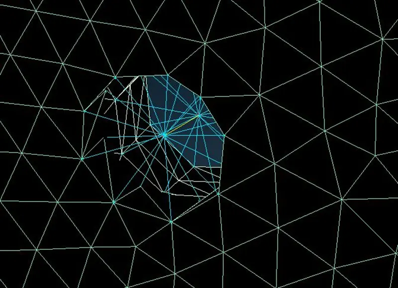
Fig 9: RBE2 bolt connection
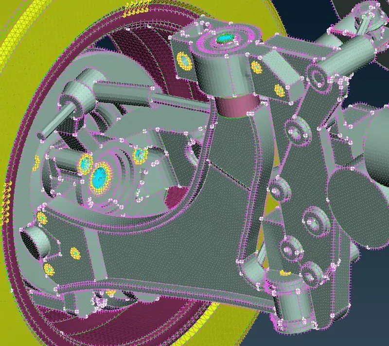
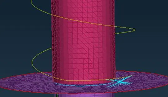
Fig 10: Cluster RBE2 connection
After the connections, I used the symmetry option to reflect the other side of the assembly. I used 3 point plane option for the plane option.
Learning Outcomes:
- Learned creating 1D elements for spring
- Learned 2D and 3D mesh.
- Learned connections
Result: Achieved all types of mesh 1D, 2D, and 3D mesh on the assembly. And given connections between the components. Some components are having very small surfaces so, I had to defeature them to clear the elements. No off elements are present in the assembly.
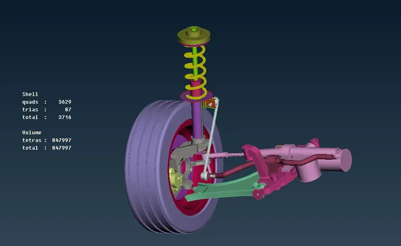
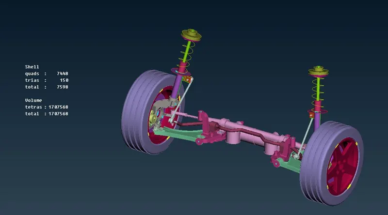
Fig 11: After finishing of meshing