Project - 2 - Meshing on the suspension Assembly
AIM:
To create an FEA mesh for a given model with suitable mesh with perfect quality and make connections between each model assemblies.
OBJECTIVE:
A rear suspension assembly should have meshed with proper mesh style. This model consists of both sheet model and solid bodies. The element created while meshing should be within quality criteria. At last model connections are made between them.
THEORY:
Modern suspensions are composed of hundreds of different parts and vehicles vary tremendously in their suspension designs but every suspension is compsed of certain basic parts which are common.
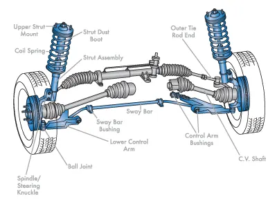
The basic components of a suspension system are,
1.CONTROL ARM:
A movalbe lever that fastens the steering knuckle to the vehicle body.
2.CONTROL ARM BUSHING:
A sleeve which allows the control arm to move up and down on the frame.
3.STRUT ROD:
It prevents the control arm from swinging to the front or rear of the vehicle.
4.BALL JOINTS:
A swivel joints that allows the control arm and steering knuckle to move up and down as well as side.
5.SHOCK ABSORBER:
It keeps the suspension from continuing to bounce after spring compression and extension.
6.STABILIZER BAR:
It will limits the body roll of the vehicle during corenering.
7.SPRING:
It supports the weight of the vehicle and permits the control arm and wheel to move up and down.
PROCEDURE:
STEP-1 (IMPORTING THE MODEL):
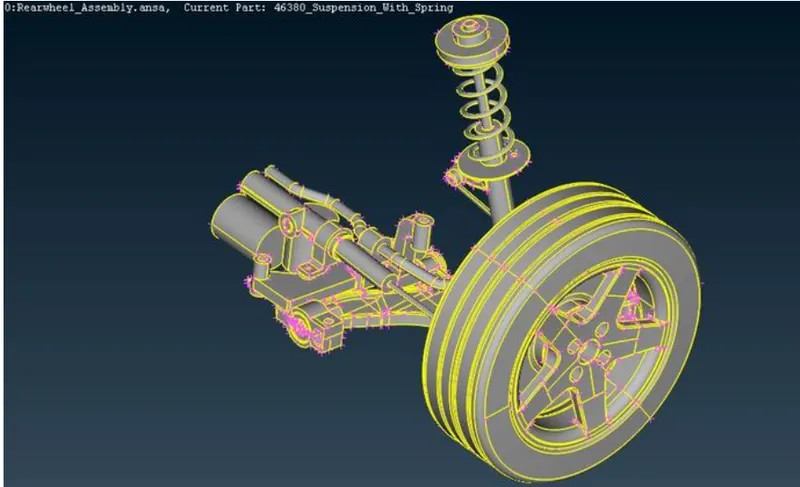
1.Import the suspension model to ANSA software.
STEP-2 (GEOMETRY CHECKUP):
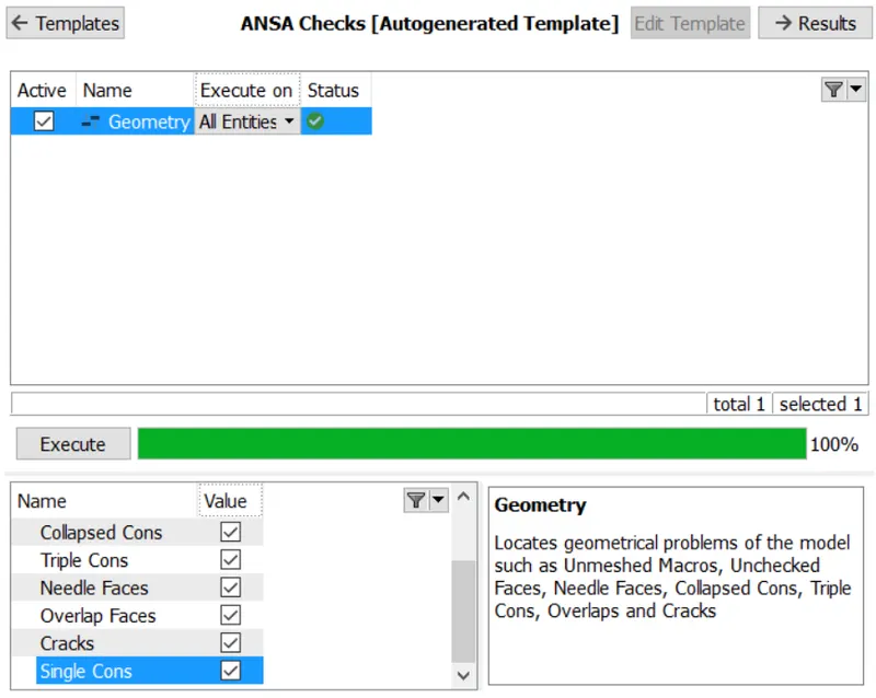
1.As per the given property we need to check the geometry of model by using Check > geometry option.
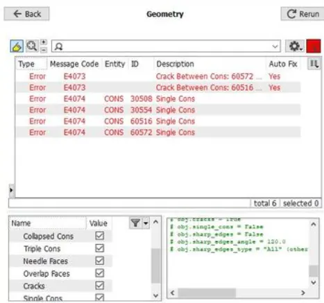
2.Fix the geometrical errors manually.
STEP-3 (CREATING A PID):
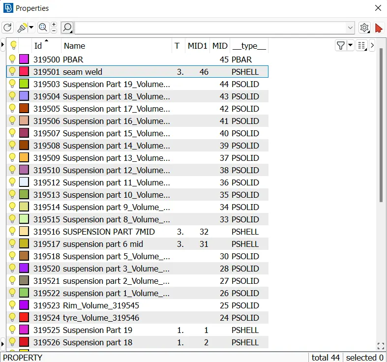
1.After the geometry clean up we need to set the new PID'S for the model.
2.In the given model we already have 3 PID's.
3.The tyer and rim are already given but the suspension part of the model has been given as a single PID so we have to use the PID region option and assign new PID's for each part in the suspension.
STEP-4 (TOPOLOGY PROCESS):
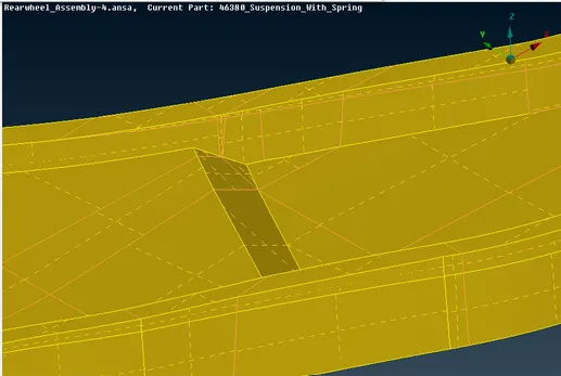
1.After new PID's are created we have to do some topological cleanup by using Cut option and creating a new faces by using New option in Faces command in Topo module on the model.
STEP-5 (MID-SURFACE PROCESS):
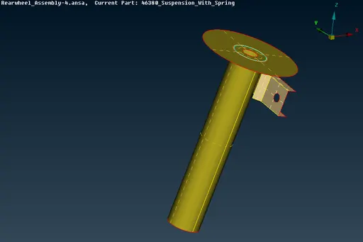
1.For some points in the model which has the thickness below 5mm and have uniform thickness we have to get the Mid Surface in order to mesh them.
2.So to get mid surface use Offset opiton in Faces loacted in TOPO module.
STEP-6 (ASSIGNING QUALITY CRITERIA AND MESH PARAMETERS):
1.Now we need to apply quality criteria and mesh parameters and model the suspension assembly accordingly.
2.For assiging the quality criteria and mesh parameters for any model we have to go to the Utilities command in which we can find the quality criteria and mesh pararmeters options.
3.The given quality needed to be used to the mid surface only when the thickness is uniform and less than 5mm.
STEP-7 (MESHING PROCESS):
1.After the quality criteria and mid surface is assigined we have to mesh the model.
2.Apply the quality given to the tyre and rim then by using spot meshing option the mesh generation which is in the mesh modules mesh the tyer and rim.
3.Select the mesh type as Tria.
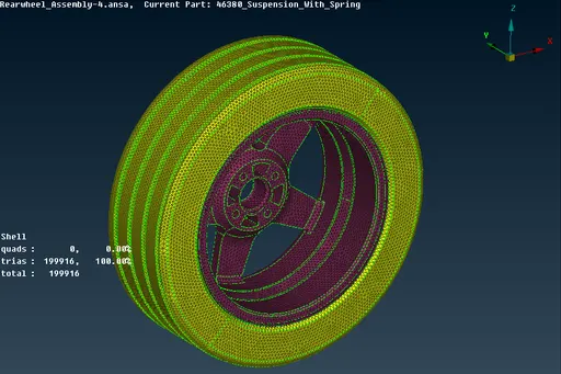
4.Use Reconstruct option in Shell mesh which is in Mesh module to improve the mesh quality and get rid of OFF elements.
5.After completing the meshing on the tyer and rim we have to do the volume mesh on them.
6.For that we have to go to the Volume mesh module.
7.To define the volume we have to use define option in Volumes which is in Volume mesh module.
8.After the volume is defined by using Tetra elements in Unstructured mesh which is in volume mesh module mesh the define parts.
9.Repeat the same process for the Non-Uniform thickness components other than tyre and rim by applying them the given quality.
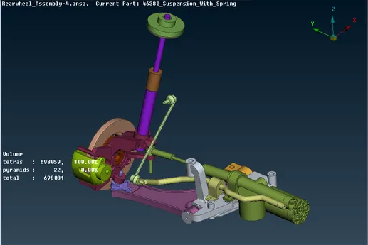
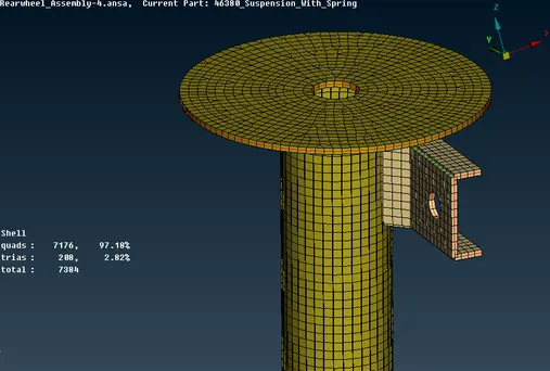
10.For unifrom thickness part which has thickness less than 5mm we have to first obtain the mid by using offset option after that the set the given quality criteria and mesh parameters and then set the element type to mixed in mesh parameters.
11.After all this mesh the mid surface by using the spot mesh option and improve the mesh by using reconstruct option and get rid of OFF elements.
STEP-8 (RBE2 CONNECTION, SEAM LINE, PBAR CONNECTION):
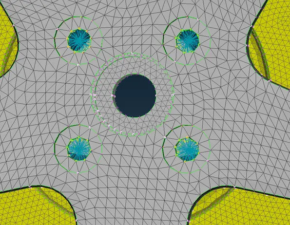
1.After meshing on the suspension model is done we have to connect the parts by using Connections by NASTRAN in Deck Modules.
2.Most of the connections in the model are RBE2 connections which has be done by using RBE2 option in Elements which is in Decks Module.
3.To perform RBE2 connections click on RBE2 and select the nodes in the place where u want to create the connection and then confirm it and the connection will be created.
4.Nodes can be selected in many ways by using Nodes or ENT options in Feature Selection option.
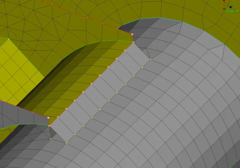
5.We also have some parts in which we have to perform the Seam weld connections.
6.To perform the seam welding connections we have to first create a curve using the CONS.
7.For creating curves by using CONS we have to use CONS to CURVES option in Curves which is in Topo module.
8.Then the curve should be converted to Seam line by using Convert option in Assembly option.
9.After the Seam line is created we have to go to Assembly > Connections > Shift + ? > Overlap shell > Realize.
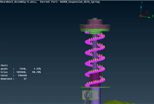
10.In suspension assembly, we have a spring in which PBAR conection need to be created.
11.We have to create a curve by using the Curve Middle option in Curves in Topo moduleand connect it by using connect option.
12.After the curve is created we have to create the CBAR connection by using CBAR option in Element's which is in NASTRAN Decks.
13.Goto NASTRAN Deck > Elements > CBAR > Select orientation > Curve > Select point > Create a new PID > Assigin radius.
14.The PBAR connection is created.
STEP-9 (REFLECTING THE MODEL):
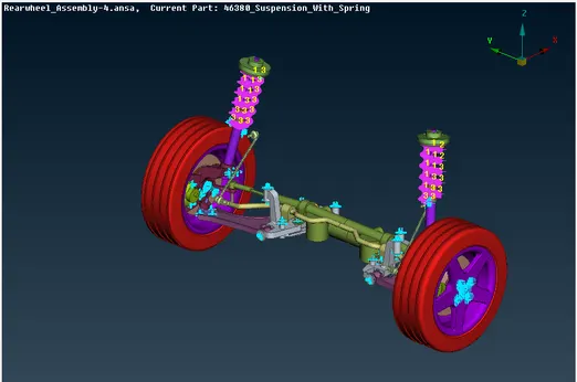
1.After all the meshing and connection are completed on the model we have to now Reflect the model by using Symetry command to complete the model to the other side.
2.To perform symmetry goto Utilities > Transform > Copy > Symmetry > Finish, to get the reflection of the model to other side.
OBSERVATION:
Thus the meshing on the given suspension assembly model according to the given quality criteria and mesh parameters is done and Suitable connections to connect the suspension assembly and perform the symmetry command to reflect the half of the finished model to the other side is done.
RESULT:
Thus the final model has been created with FEA elements with proper mesh quality and connection between model is created and quality check is performed sucessfully using ANSA software.
DRIVE LINK : https://drive.google.com/file/d/1zcSeJ4FdgIhSqTkJ7UgM_veblodl17kn/view?usp=sharing