Project - 2 - Meshing on the suspension Assembly
Aim- To mesh and to provide the connection for the suspension assembly.
objectives-
1.To do the volume mesh the for the tyre and the for the rim .
2.To the volume mesh for the other compoments whose thickness is more than 5mm.
3.To do the shell mesh for the compoments hving thickness less than the 5mm.
4. To provide connection like bolt,RBE2 and spring of the supsension assembly.
Quality Criteria for Surface Meshing of Tyre and Rim (Element type: Tria) :
|
S.No |
Quality Criteria |
Value |
|
1 |
Target/Average length |
6.5 |
|
2 |
Minimum Length |
5 |
|
3 |
Maximum Length |
10 |
|
4 |
Skewness |
45 |
Quality criteria for Surface Meshing of Non Uniform thickness components other than Tyre and Rim (Element type: Tria) :
|
S.No |
Quality Criteria |
Value |
|
1 |
Target/Average length |
4 |
|
2 |
Minimum Length |
2 |
|
3 |
Maximum Length |
6 |
|
4 |
Skewness |
45 |
Quality Criteria for Volume meshing of all Non Uniform thickness components (Element type: Tetra Elements):
|
S.No |
Quality Criteria |
Value |
|
1 |
Tet-collapse |
0.2 |
Quality criteria for Mid surfacing of Uniform thickness part which has thickness less than 5 mm (Element type: Mixed elements) :
|
S.No |
Quality Criteria |
Value |
|
1 |
Target/Average length |
4 |
|
2 |
Minimum Length |
2 |
|
3 |
Maximum Length |
6 |
|
4 |
Aspect |
3 |
|
5 |
Warpage |
15 |
|
6 |
Skewness |
45 |
|
7 |
Jacobian |
0.7 |
|
8 |
Minimum Quad Angle |
45 |
|
9 |
Maximum Quad Angle |
135 |
|
10 |
Minimum Tria Angle |
30 |
|
11 |
Maximum Tria Angle |
120 |
Procedure-
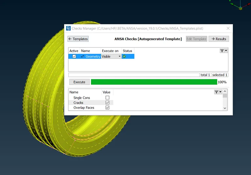
1. For the tyre and rim we are going to do volume mesh . first we check the geometry for any errors like single con.convex face,needle face etc in the check manger. if errors are found they are fixed manully or fixed automatically.
2. Next we set PId for the tyre topo>faces>set PID>selecting the compoment and the new PSHELL and double click on the compoment.
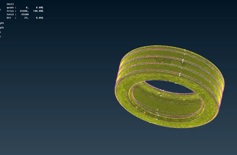
3.we will set the meshing paramter and the quality parametrs in the tab and we mesh compoment manully using the tria elemnts
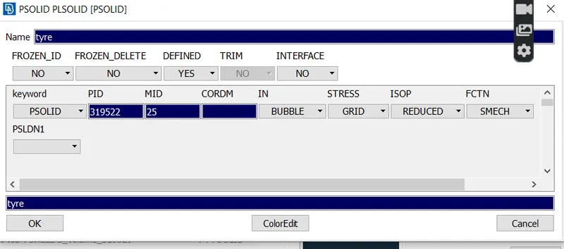
4.Now we convert the shell elemnts in to solid elemnts. first we need to define the close volume for the compment Volume> Define>manully>manully> select the compoment>right click>set PID for solid>double click on the compment.
5.Now we have defined volume for the compoment next we have have mesh using the tetra fem or Tetra rapid either in list or in mesh deck.
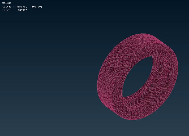
we can confirm whether the volume generted by switching the cad model and switch o n the bound mode to ensure the solid genereted.
6.simillar procedure is followed for the rim compment.
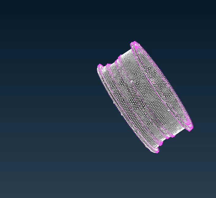
fig shell meshing of the rim.
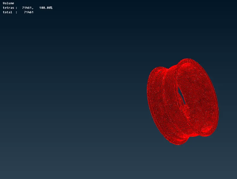
fig volume mesh for the rim compoment.
7. we will do shell meshing using mixed elements either by casting or by manully,hre casting matod is followed casting method genertes th mid surfaces on its own and mesh the mid surface according to quality ceteria.
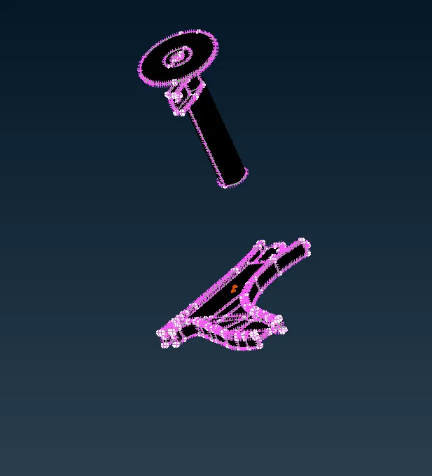
for the above compoments we will shell meshing using the casting method.
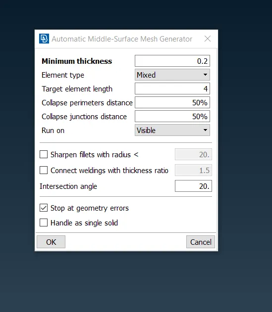
fig- casting method details
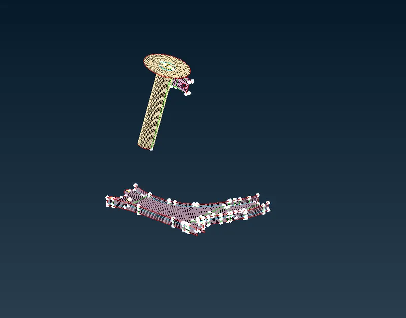
fig- Shell meshing of the compoments using the casting method.
8.The others parts of the suspension are meshed manuuly or by batch mesh according to qulity certeria and generted volume mesh.
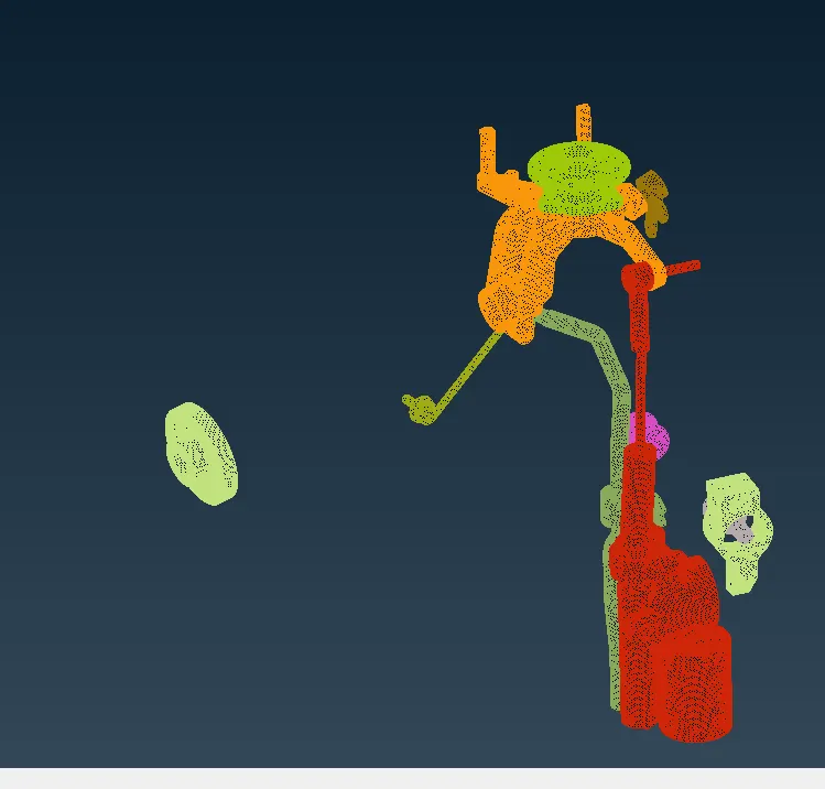
9. we provide connection such as rbe2,and we convert the spring of the supension in to 1D bar elements nad 1d bar elemnts are converted in to solid elemnts.
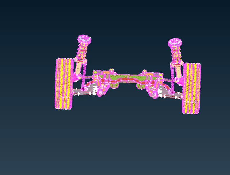
10.we carry out the symmentry option by using
outcomes-
1. able to do topological clean up.
2.Assign PIDS for seperate compoments and for diffrent volumes,
3.Meshed all the compoments with the given quality certeria.
4.Understood tthe concepts of connections deployed diffrent connection to the diffrent compoments.