Project - 2 - Meshing on the suspension Assembly
Aim: Create 3D tetra mesh and connections to the given suspension system assembly.
Objective: The given suspension system which was cleared off the geometrical errors which was meshed with 2D elements and the 3D tetra elements are created with good mesh deployed with connection using RBE2 elements and the overlap joint.
The quality criteria followed:
For Quality Criteria of surface mesh 2D of Tyre and rim (element type: tria):
- Target/Average length: 6.5
- Minimum length: 5
- Maximum length: 10
- Skewness: 45
For Quality Criteria of non-uniform component other than Tyre and rim (element type: tria):
- Target/Average length: 4
- Minimum length: 2
- Maximum length: 6
- Skewness: 45
For 3D Mesh Quality:
- Collapse: 0.2
For Quality Criteria of Mid surface of Uniform thickness part which has thickness less than 5mm (element type: Mixed element):
- Target/Average length: 4
- Minimum length: 2
- Maximum length: 6
- Skewness: 45
- Aspect: 3
- Jacobian: 0.7
- Warpage: 15
- Minimum quad Angle: 45
- Maximum quad Angle: 135
- Minimum tria Angle: 30
- Maximum tria Angle: 120
Procedure:
- Download the given file which was in “IGS” format. Open in ANSA software, save it in “. ansa” format.
- The geometry is refined using the “length” option in mesh module, perimeter and macros are set to 5.
- The model is set for grey orientation using the orient option after topo is used to stitched the geometry in the Topo module.
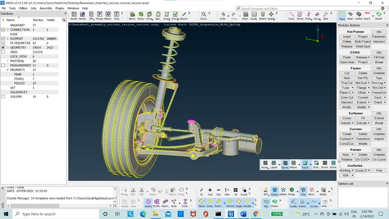
Figure 1: After orientation and Topo
- Each and all parts are meshed with “ortho tria” using the spot mesh for the curved area using the mesh module.
- The remaining flat areas are mesh using the “tria” in the spot mesh in the mesh module.
- The model is checked for “OFF” elements and cleared for maximum and minimum length using the “reconstruct” option in the shell mesh option. And knink were Avoided.
- The model is now with each part individually meshed with 2D tria elements with the tyre and rim quality criteria to be followed and other rest of the parts following other quality criteria as metioned in the requirement.
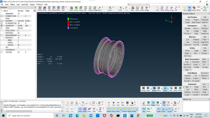
Figure 2: Surface Mesh of Rim
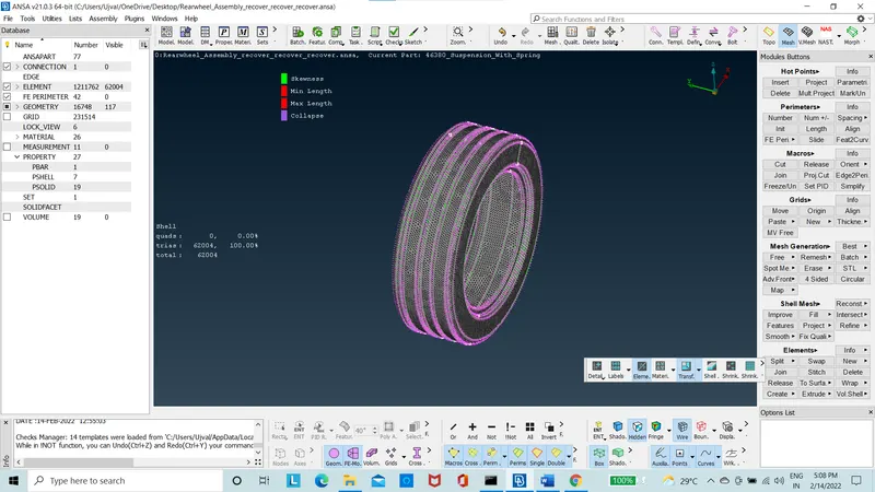
Figure 3:Surface Mesh of Tyre
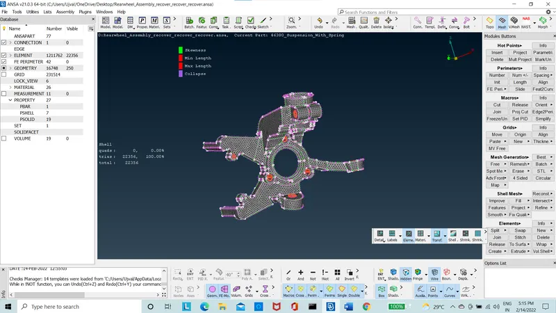
Figure 4:Surface Mesh of connector
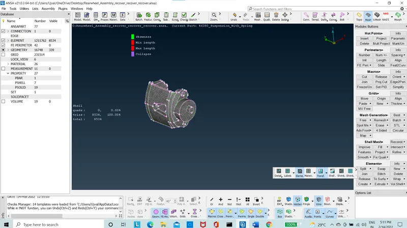
Figure 5:Surface Mesh of Break
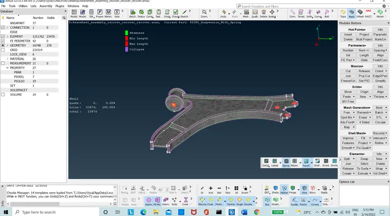
Figure 6: Surface Mesh of lower Arm
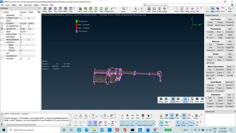
Figure 7:Surface Mesh of Stabalizer
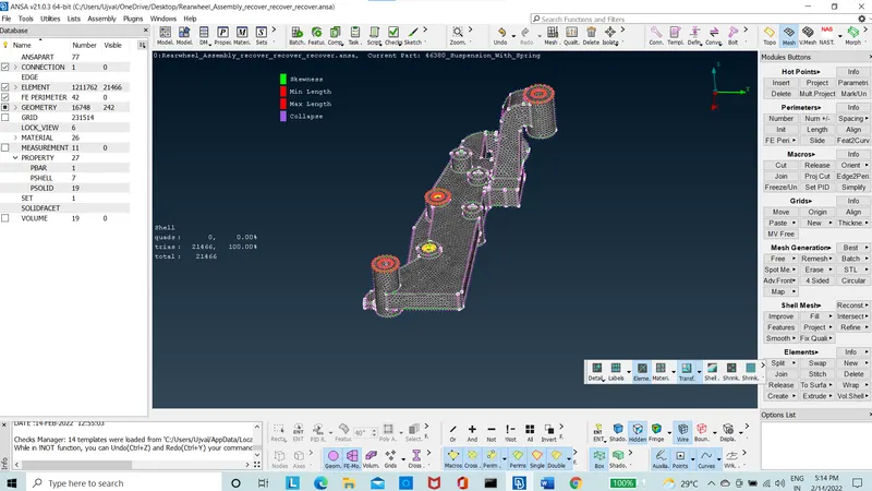
Figure 8:Surface Mesh of Lower control arm

Figure 9:Surface Mesh of Sway Bar
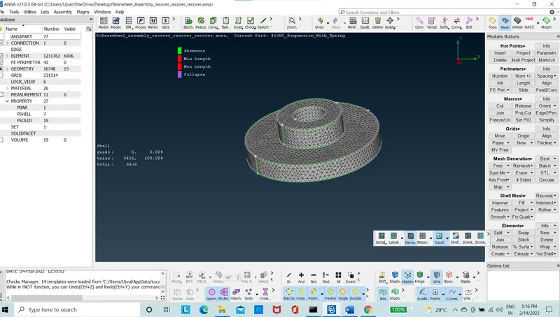
Figure 10:Surface Mesh of Top Sleeve
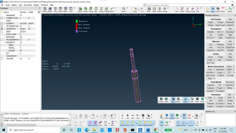
Figure 11: Surface Mesh of Shock Absorber
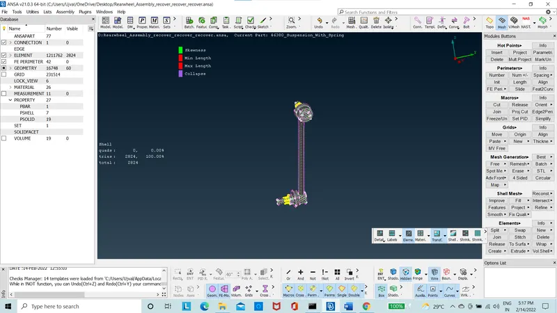
Figure 12:Surface Mesh of Link rod
- The volume is defined using the “Define” option manual, in the volume mesh module.
- All the parts are created with the mesh of 3D tetra model.
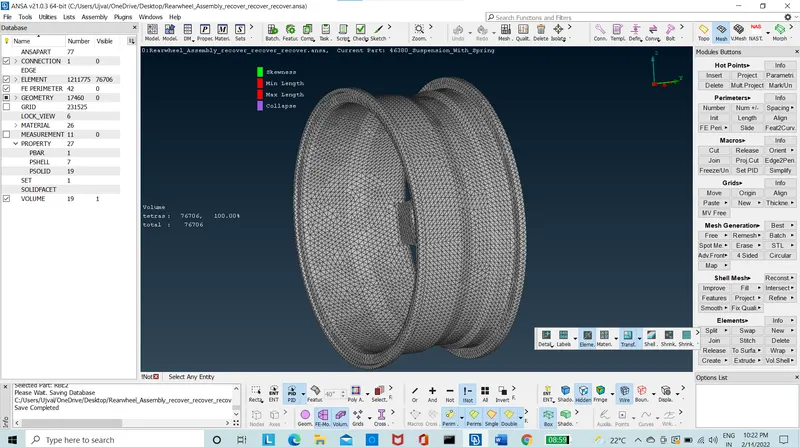
Figure 13: Tetra Mesh of Rim
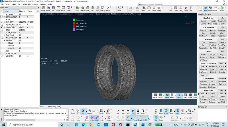
Figure 14: Tetra mesh of tyre
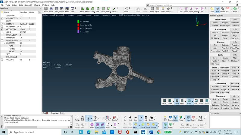
Figure 15: Tetra mesh of Connector
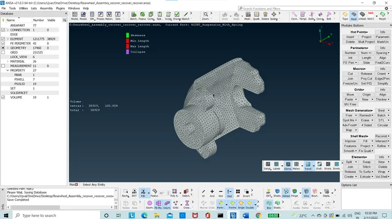
Figure 16: Tetra mesh of Break
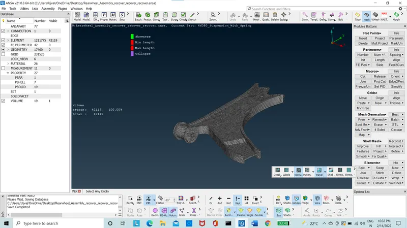
Figure 17: Tetra mesh of Lower Arm
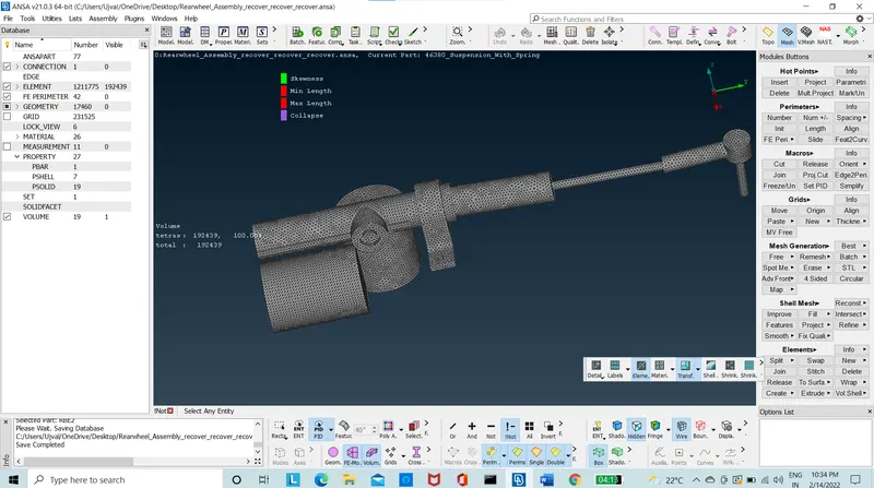
Figure 18: Tetra mesh of Stabalizer
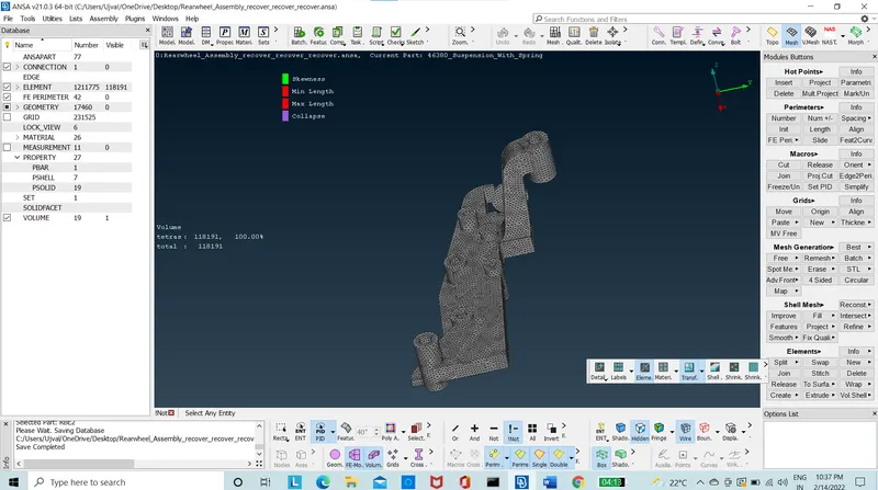
Figure 19: Tetra mesh of Lower Control Arm
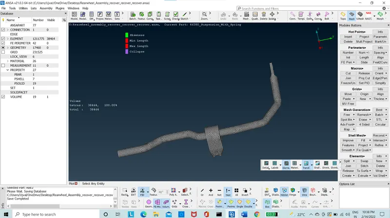
Figure 20: Tetra mesh of Sway Bar
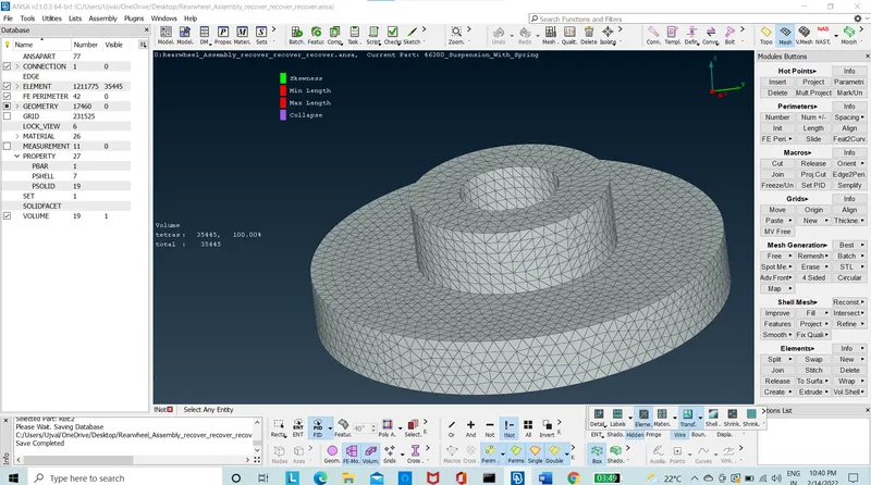
Figure 21: Tetra mesh of Top Sleeve
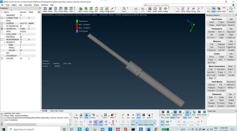
Figure 22: Tetra mesh of Shock Absorber
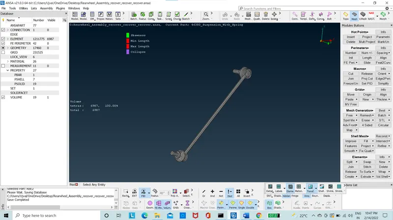
Figure 23: Tetra mesh of Link Rod
- Using the “list” option in the volume mesh module, the volume is meshed using the unstructured mesh of “tetra FEM”.
- The model is checked for “collapse” quality criteria and “OFF” elements are zero.
- There are two parts with uniform thickness that is mid meshed one with automatic Skin mesh that is the bracket.
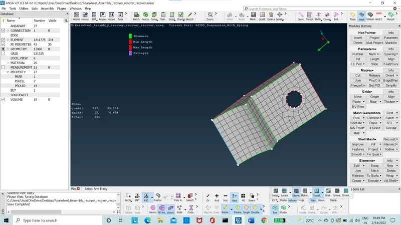
Figure 24: Mid Mesh of Bracket
- The other part is manually mid surfaced and meshed.
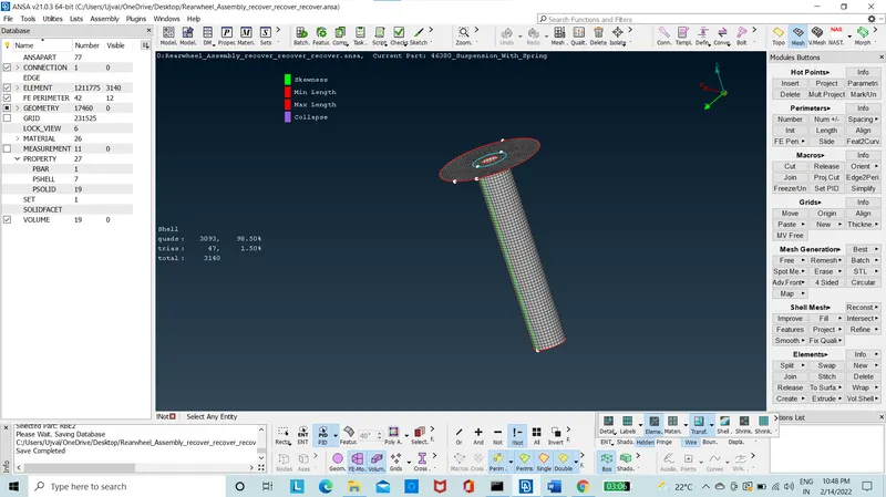
Figure 25: Mid mesh of Shock Absorber
- The mixed elements are then released from the geometry by using the “release option in the mesh module.
- The connection of RBE2 elements used to connect the parts using cluster RBE2 and Two node RBE2.
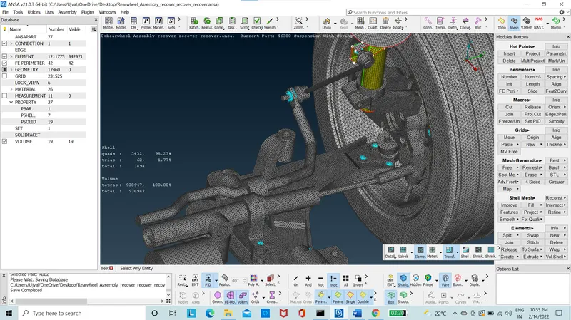
Figure 26: Suspension system with Connections
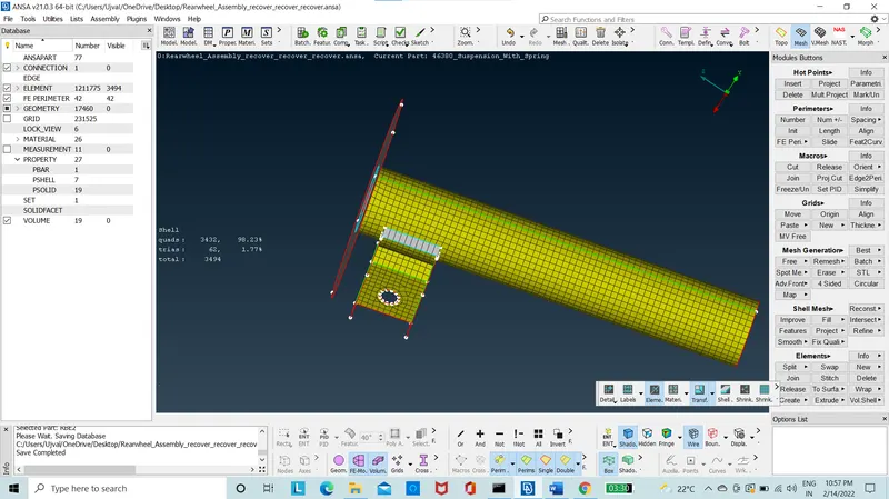
Figure 27: Mesh With Overlap Weld joint
- The overlap joint is used to connect through the mid meshed parts using the convert curve to seam line and using the connection manager in the assembly option.
- The spring is taken as 1D Bar element.
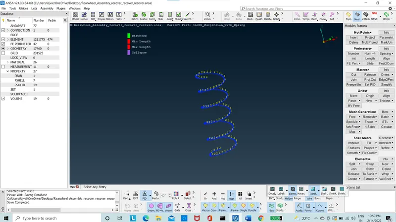
Figure 28: spring elements of 1D bar
Conculsion:
The Suspension system is meshed with 3D Tria elements and 2D Mid mesh with mixed elements, the connection were deployed with 2D RBE2 elements and using the cluster and two node methods. The connections were rigidized also using the overlap weld method.
New things Learnt:
- Create Tetra to Large complex assembly system.
- Connection deployment on complex system.
- Create tetra FEM mesh.