Project - 2 - Meshing on the suspension Assembly
PROJECT 2: MESHING ON THE SUSPENSION ASSEMBLY
Objective: The Main Aim of This Project is to Perform 2D and Solid Meshing on Suspension Assembly as per the Quality Criteria Shown Below and to Deploy Necessary Connections.
Table 1: Quality Criteria for Surface Meshing of Tyre and Rim (Element type: Tria) :
|
S.No |
Quality Criteria |
Value |
|
1 |
Target/Average length |
6.5 |
|
2 |
Minimum Length |
5 |
|
3 |
Maximum Length |
10 |
|
4 |
Skewness |
45 |
Table 2: Quality criteria for Surface Meshing of Non Uniform thickness components other than Tyre and Rim (Element type: Tria) :
|
S.No |
Quality Criteria |
Value |
|
1 |
Target/Average length |
4 |
|
2 |
Minimum Length |
2 |
|
3 |
Maximum Length |
6 |
|
4 |
Skewness |
45 |
Quality Criteria for Volume meshing of all Non Uniform thickness components (Element type: Tetra Elements):
|
S.No |
Quality Criteria |
Value |
|
1 |
Tet-collapse |
0.2 |
Table 4: Quality criteria for Mid surfacing of Uniform thickness part which has thickness less than 5 mm (Element type: Mixed elements) :
|
S.No |
Quality Criteria |
Value |
|
1 |
Target/Average length |
4 |
|
2 |
Minimum Length |
2 |
|
3 |
Maximum Length |
6 |
|
4 |
Aspect |
3 |
|
5 |
Warpage |
15 |
|
6 |
Skewness |
45 |
|
7 |
Jacobian |
0.7 |
|
8 |
Minimum Quad Angle |
45 |
|
9 |
Maximum Quad Angle |
135 |
|
10 |
Minimum Tria Angle |
30 |
|
11 |
Maximum Tria Angle |
120 |
Procedure:
- Import Cad Geometry = File - Open - Select Geometry.
- The given CAD Geometry imported in ANSA workbench and orientation checked.
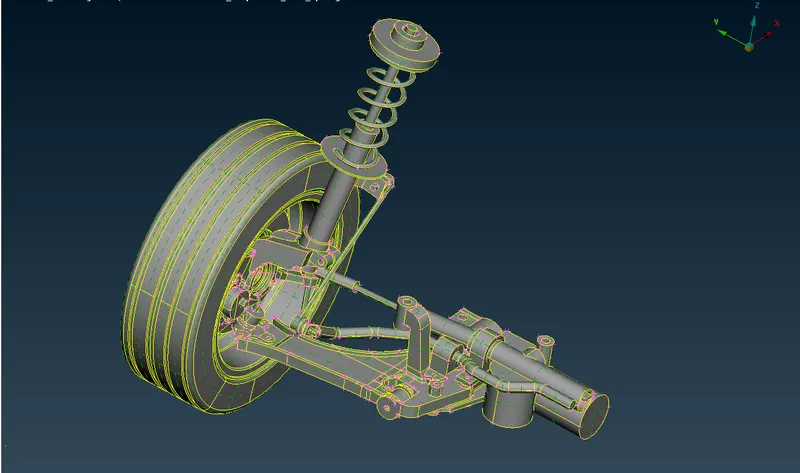
- Image 1: Imported CAD Model (Suspension Assembly)
- Geometry Clean-UP = Tools - Checks - Geometry. Errors are resolved automatically by using fix command in geometry.
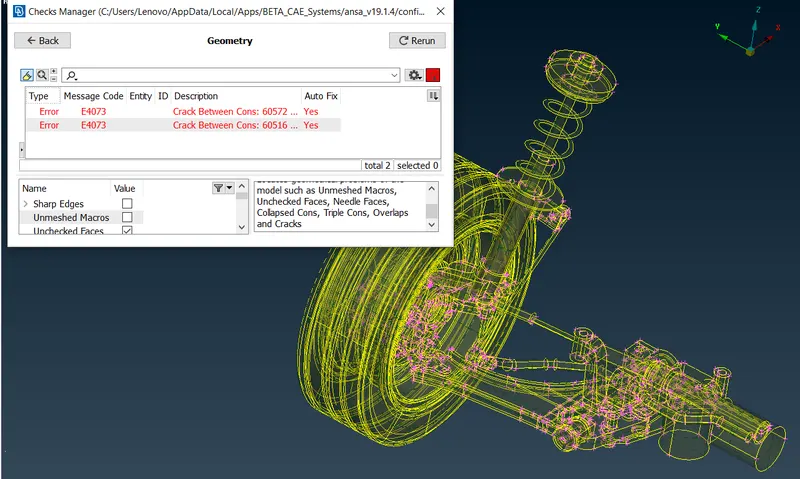
- Image 2: Before Geometry Clean-up
- Topo - Faces - Topo Command used to clear issues with the orientation
- All geometrical errors are cleared using auto FIX option.
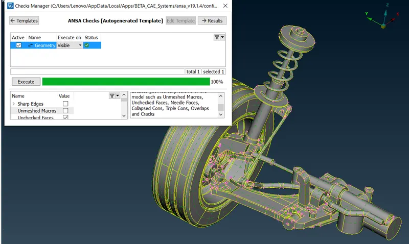
- Image 3: After Geometry Clean-up
- Thickness Measurement : Thickness measured using Utilities - Measure. As this is a Plastic Component (Suspension Assembly). It has a same thickness throughout the model as shown in Image 4.
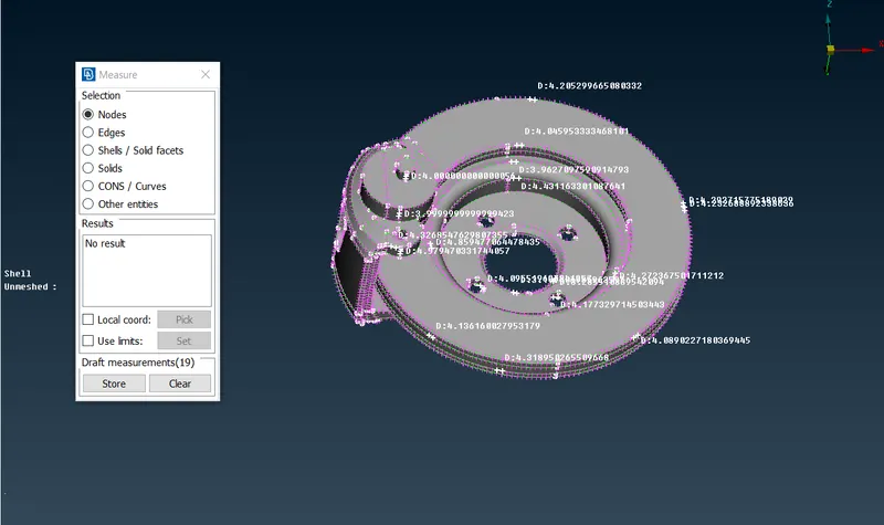
- Image 4: Thickness Measurements
- PID Creation: Separate Property ID Created for all different part IDs.
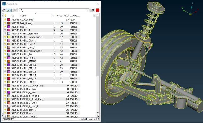
- Image 5: PID Creation
- Mid Surface Generation:
- The resolution of CONS improved using Mesh - Length - Perimeters - Macros.
- Topo - Faces - Offset, Topo - Faces - Middle used to find the mid surface.
- Also, Topo - Faces - New / Cut, Topo - Cons - Project, Transform - Copy - Rotate Commands used to find the mid surface.
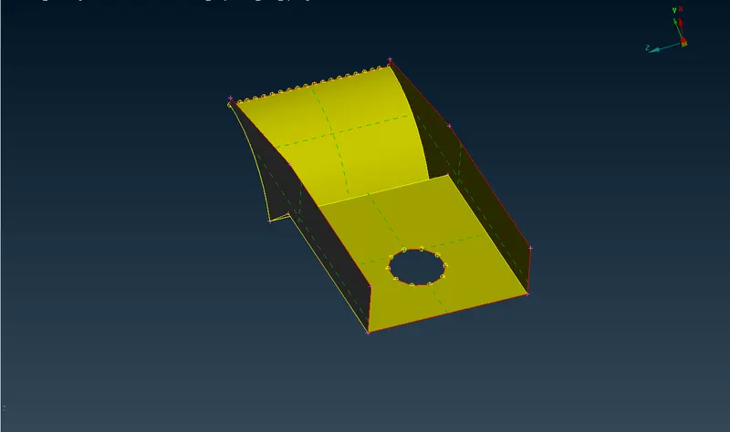
- Image 6: Mid Surface
- Mesh Generation : The perimeter elemental length is set using Mesh - Perimeter - Length, Mesh - Perimeter - Macro option.
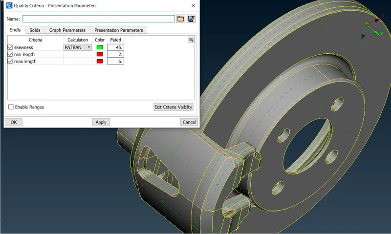
- Image 7: Quality Criteria - Presentation Parameters
- The Quality Criteria Shown in table no. 1 are applied to the model using Utilities - Quality Criteria
- Mesh Parameters are applied using Utilities - Mesh Parameters.
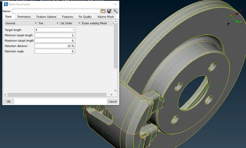
- Image 8: Mesh Parameters
- F11 Function Key is a shortcut for Quality Criteria - Presentation Parameters.
- Mesh is done using Mesh - Mesh Generation - Spot Mesh.
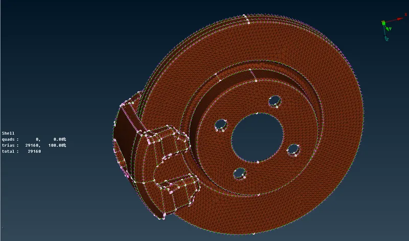
- Image 9: Mesh Generated
- For better results of mesh Mesh - Shell Mesh - Reconstruction used.
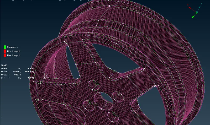
- Image 10: Mesh Generated as per Quality Criteria
- Volume mesh is generated by using Volume Mesh - Unstructured Mesh - Tetra Rapid.
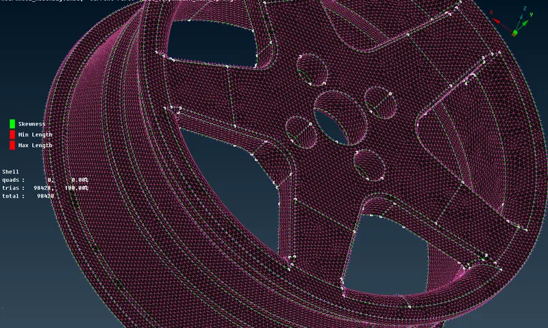
- Image 11: Volume Mesh Component
- Volume Mesh - Volumes - Define - Create New Part ID -PSOLID. Hence Volume is Defined.
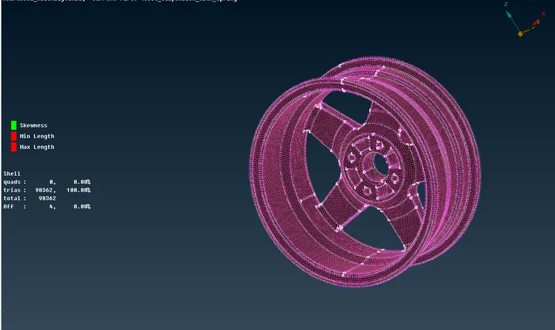
- Image 12: Improved Meshed Quality Component
- Mesh Improvement is done using Reconstruct, Smooth, Split, Swap, Paste, Cut, Join etc under Mesh tab.
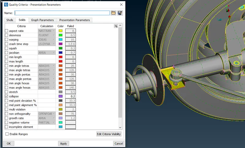
- Image 13: Tet collapse Quality Checking
- The surfaces are split to get better mesh flow using Mesh -Macros -Cut.
- Connections: To create Connections Topo - Curves - Cons2Curve is used to create the curves from Cons.
- Then, Assembly - Convert - Curves - Seam Line is used to convert curves to seam line connections.
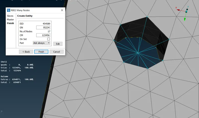
- Image 14: RBE2 Many Nodes Connections
- Then, Assembly - Connection's tab used to define the RBE2 - Many Nodes.
- RBE2 - Two Nodes used to create Bolt Connections from NASTRAN Deck Element - RBE2 nodes.
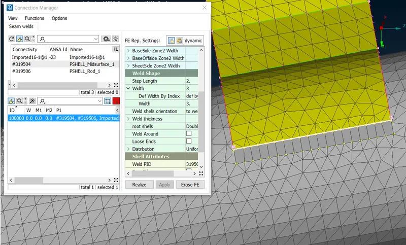
- Image 15: Seam Weld Connection
- Overlap - Shell used as a FE representation type.
- RBE3 - Hexa - RBE3 connections defined by the connection manager followed by the creating new PSolid ID.
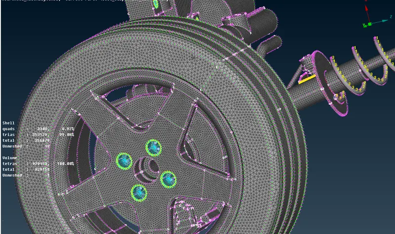
- Image 16: Bolt Connections
- Overlap Shell Connections = To create Connections Topo - Curves - Cons2Curve is used to create the curves from Cons.
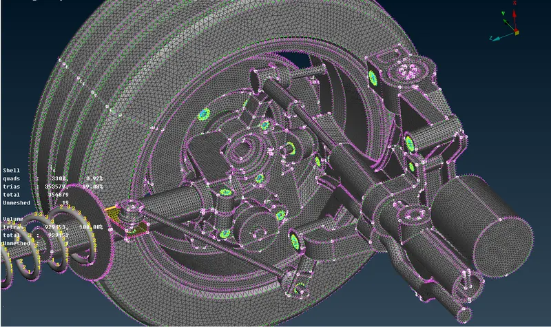
- Image 17: Bolt and Seam Weld Connections
- Then, Assembly - Convert - Curves - Seam Line is used to convert curves to seam line connections.
- Symmetry Operation Carried out by using Transform - Copy - Symmetry - Mirror 3 Points Plane - Apply - Ok.
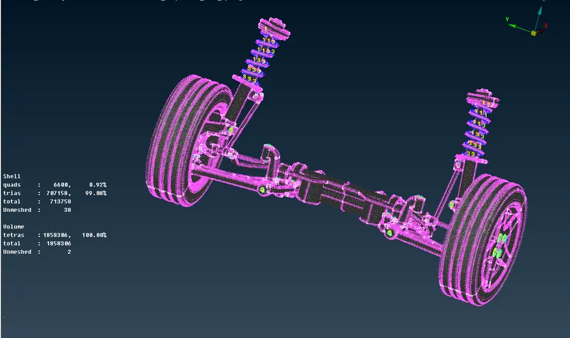
- Image 18: Suspension Assembly Symmetry
Results:- The given Suspension Assembly is meshed as per the given quality criteria. The thickness assigned to the meshed Suspension Assembly. The appropriate connections are provided for Suspension Assembly by using NASTRAN Deck.
Conclusion:- From this challenge I learned about Suspension Assembly CAD model import, Geometry clean-up, New PID creation, Mid surface extraction, setting up Quality Criteria, Mesh generation, Reconstruction of mesh using quality criteria, Assigning Thickness to Meshed Model. Also, Mesh Generation using Tetra elements and Ortho Tria, Reconstruction of mesh as per given quality criteria to check Tet collapse, Volume Meshing, Surface Meshing. Creation of connections such as RBE3 - CBUSH - RBE3, OVERLAP SHELL, RBE3 - HEXA - RBE3, Rigid Connections, Bolt Connections, Seam line Connections.