Project - 2 - Meshing on the suspension Assembly
Aim
For the given assembly:
a) Check for the geometrical errors
b) Use the suitable mesh technique to mesh the model
c) After meshing, deploy the suitable weld and rigid connections to the given model as per the instructions
d) Assign the PID's one by one to the different subsystems.
e) Take a symmetry action about the standard plane and mirror the entire assembly
Procedure
1. Imparting the model
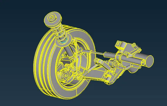
First of all, model has been imparted to ANSA and after imparting model was visualised carefully to get different PID's. The given model is given as below:
2. Geometry Cleanup
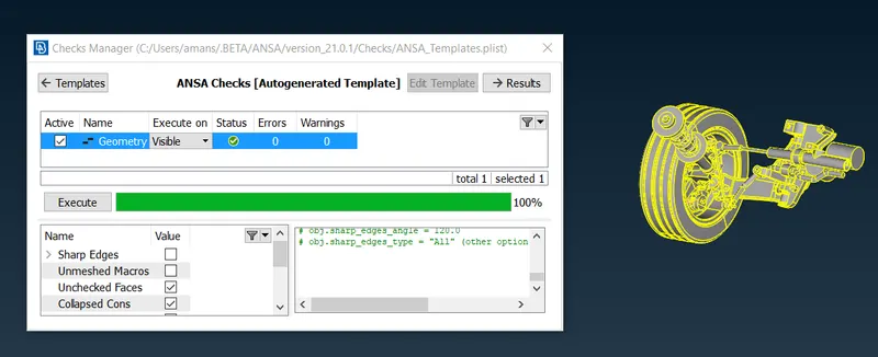
After imparting the model, a geometry check was carried out using check option. There were no any issue in the given CAD data. The check data is given below:
3. Tyre and Rim
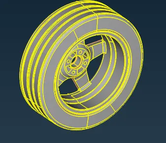
Tyre and rim part of the given cad model was assigned as PSHELL ID and after that these two features were taken care seperately. Geometry of these two are given as:
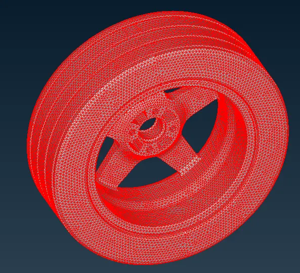
Meshing of these two features were carried out seperately after assigning the PID's using volume meshing module. First of all the surface spot mesh was given as per the given below quality criterion:
|
S.No |
Quality Criteria |
Value |
|
1 |
Target/Average length |
6.5 |
|
2 |
Minimum Length |
5 |
|
3 |
Maximum Length |
10 |
|
4 |
Skewness |
45 |
th quality criteria for volume mesh is given as:
|
S.No |
Quality Criteria |
Value |
|
1 |
Tet-collapse |
0.2 |
After deploying the surface spot mesh, Tetra FEM method was used for volume mesh and after this the volume was released as FE as per given below:
A seperate PSOLID ID was assigned to the achieved volume FE.
4. Parts other than Tyre and Rim
After modeling of tyre and rim, one by one PID's were created for different parts
4.1 P2 SOLID
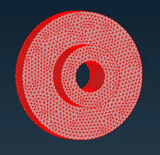
Mesh quality criteria for surfaces other than rim and tyre is given as:
S.No Quality Criteria Value
1 Target/Average length 4
2 Minimum Length 2
3 Maximum Length 6
4 Skewness 45
4.2 P3 SOLID ID
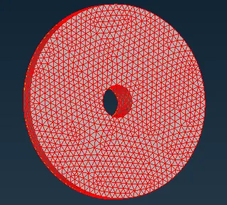
The same tetra FEM method was used for rest of the solid parts just as above.
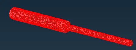
4.3 P4 Volume Mesh
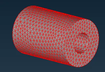
4.4 P5 Volume Mesh
4.5 P6 2D Shell Mesh
Since for this part, thickness value was less than 5 mm so 2d midsurface was extracted and mesh was deployed as per the quality criteria below:
S.No Quality Criteria Value
1 Target/Average length 4
2 Minimum Length 2
3 Maximum Length 6
4 Aspect 3
5 Warpage 15
6 Skewness 45
7 Jacobian 0.7
8 Minimum Quad Angle 45
9 Maximum Quad Angle 135
10 Minimum Tria Angle 30
11 Maximum Tria Angle 120
The FE of shell mesh is given below:
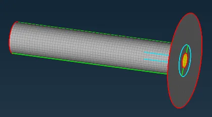
Thickness of 3 mm was assigned to the FE above.
4.6 P7 2D Shell Mesh
There was also a feature for which tickness was just below 5 mm. The given FE mesh for the same is given below:
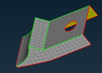
Quality criteria for this was the same as above mentioned. Assigned thickness was 3 mm.
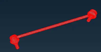
4.7 P8 Volume Mesh
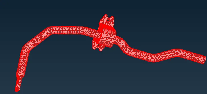
4.8 P9 Volume Mesh
4.9 P10 Volume Mesh
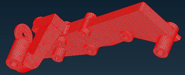
4.10 P11 Volume Mesh
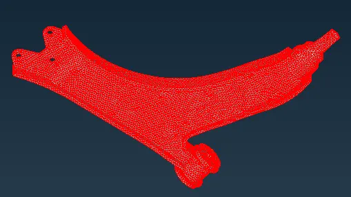
4.11 P12 Volume Mesh
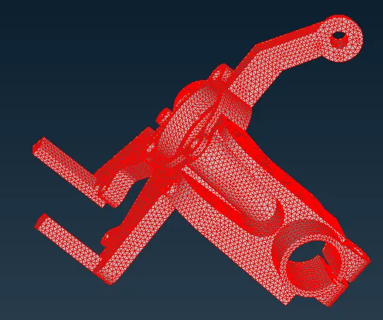
4.12 P13 Volume Mesh
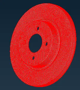
4.13 P14 Volume Mesh
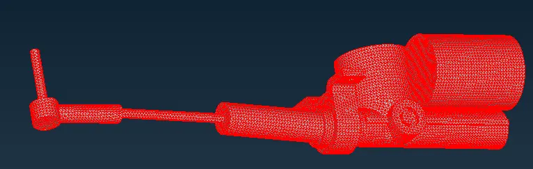
4.14 P15 Volume Mesh
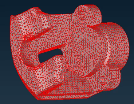
4.15 P16 Volume Mesh
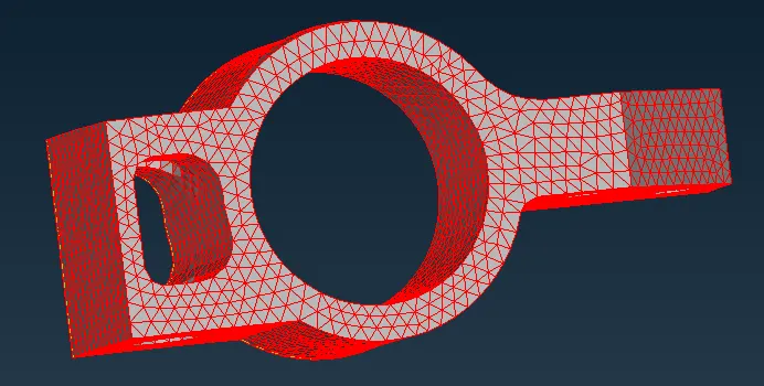
4.16 P17 Volume Mesh
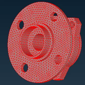
4.17 P18 Volume Mesh
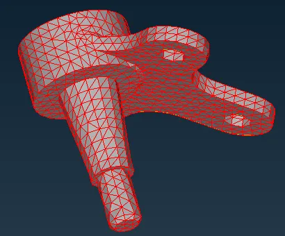
4.18 P19 Volume Mesh
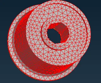
4.19 1D Spring Element
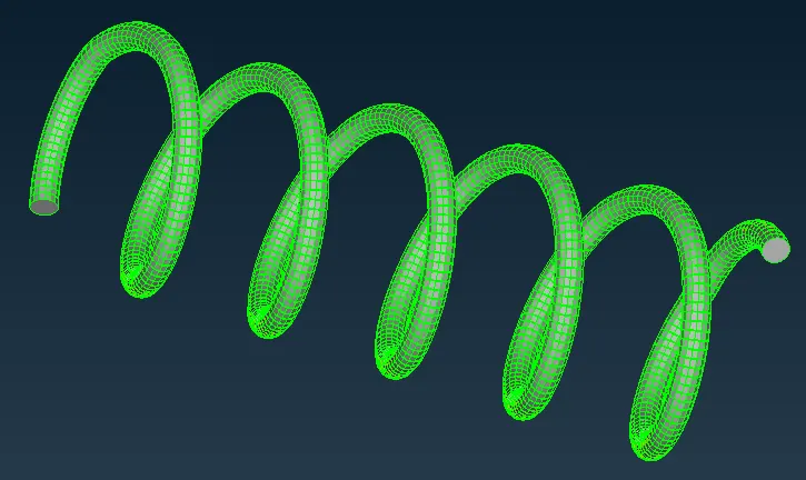
To make the spring FE, First of all middle curve option was used to make the middle curve and after that connect multi option was used to connect the dicrete parts of curve. On then other hand, to make the spring element PBAR element was used from NASTRAN Deck module. after selecting PBAR, curve selection was done by defining spring from the curve and then radius of the spring was given as 5 as per circle selection. This definition of radius has calculated the cross sectional area and moment of inertis automatically. The spring FE element is shoen above.
5. Connections
5.1 Seam Weld
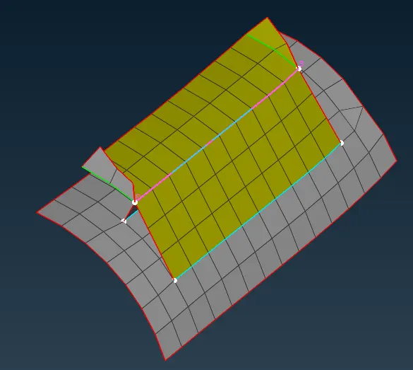
Using cons to curve option the curve was connected to make seam weld connection. After that connect multi option was used to create a single curve. Transform option from top bar was used to convert curve line to seam weld line. By going to connection manager, first the P1 surface was selected as the feature and P2 was elected as basesheet. Element size for the weld was 3.0 mm and weld type was overlap shell. Double row and search distance of 10.0 mm was used to deploy weld connection.
5.2 RBE2 Connections
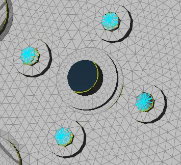
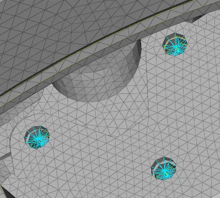
As seen above where the volume mesh were connected through holes, Many nodes and two node RBE2 connections were used to connect the bodies. First the two surfaces of a solid mesh were connected through cluster RBE2 connection and after that these clusters were connected by two node RBE2 connection.
6. Symmetry of the assembly about the plane
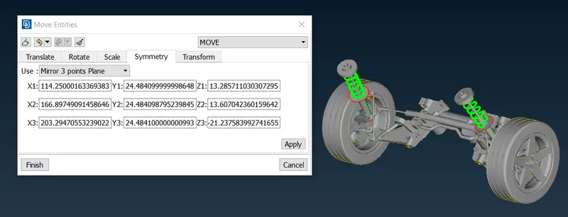
As seen in the above image, 3 points were selected from the given three outer entities and then after using the copy symmetry option the entire assembly was obtained.
Results
a) geometrical errors were vanished successfully.
b) Meshing ws done on the given assembly by creating different PID.
c) Weld and rigid connections to the given model was completed.
d) PID's were assigned to different subsystem one by one.
e) One sided system was successfully mirrored to the other side by defining the 3D point plane.
Conclusions
a) Learnt to deal with the assembly of different subsystems
b) Learnt to work on subsystems seperately
c) Learnt to select a suitable meshing method for the subsystems.
d) Learnt to deploy the connections to the assembly
Note: In some subsystems there can be off elements. Please ignore them because these were remained as such to hold the important features.
Drive link for Assembly
https://drive.google.com/file/d/1bLgYoa_q-e75Lg2aFvpj3RU8Rhkyqxdw/view?usp=sharing