Project - 2 - Meshing on the suspension Assembly
(PROJECT -2)
Meshing on Car Suspension Assembly Model
AIM:
To mesh the given suspension system model and deploy connections accordingly.
OBJECTIVE:
For the given assembly, check for the geometrical errors and mesh with the given element Quality criteria. After meshing the component the thickness has to be assigned for mid surfaces. Use tetra elements to model non-uniform thickness components. Also use Appropriate connections to connect the component.
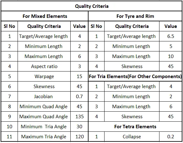
Use surface meshing, volume meshing and mid surface meshing with below given quality criteria.
INTRODUCTION:
Suspension is the term given to the system of springs, shock absorbers and linkages that connects a vehicle to its wheels. Suspension systems serve a dual purpose — contributing to the car's roadholding/handling and braking for good active safety and driving pleasure, and keeping vehicle occupants comfortable and reasonably well isolated from road noise, bumps, and vibrations,etc. These goals are generally at odds, so the tuning of suspensions involves finding the right compromise. It is important for the suspension to keep the road wheel in contact with the road surface as much as possible, because all the forces acting on the vehicle do so through the contact patches of the tires. The suspension also protects the vehicle itself and any cargo or luggage from damage and wear.
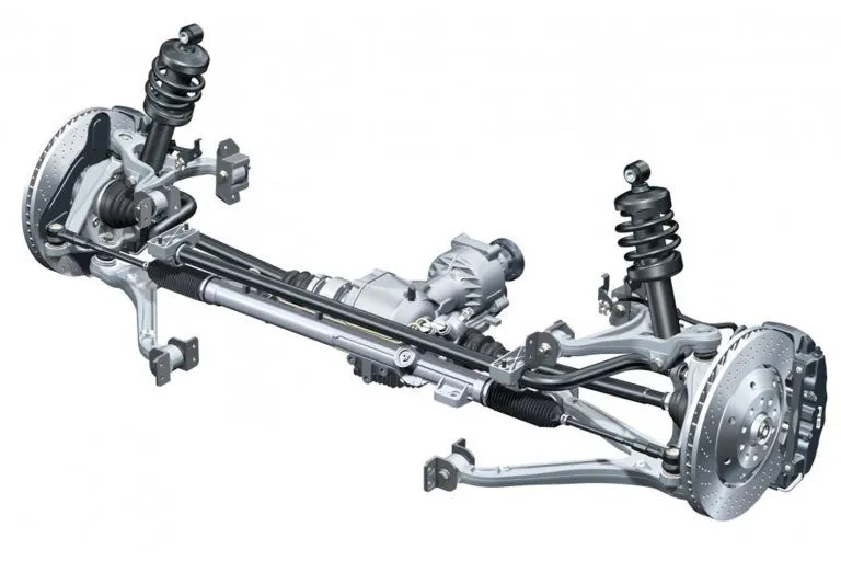
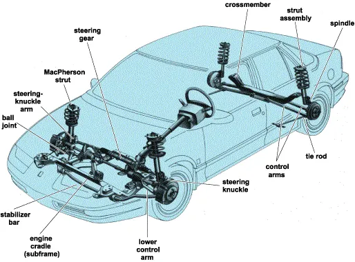
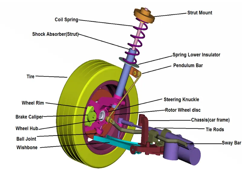
Fig: Car Suspension System
PROCEDURE:
1) Import Model CAD File:
Import CAD file into ANSA working environment and do a topo if faces are not stitched properly with each other otherwise go straight towards performing geometry checks on the model.
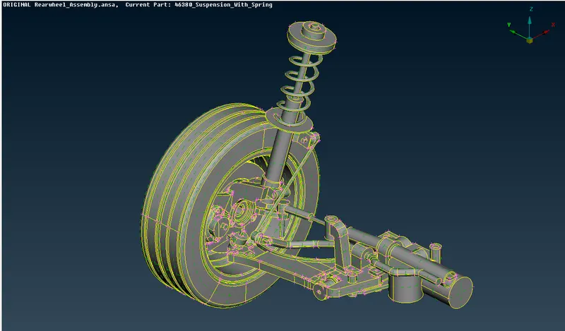
Fig: CAD Model
2) Perform Geometry Checks:
Perform geometry checks using checks manager for this, go to Tool > Checks > Geometry > Execute. Enable unchecked faces, collapsed cons, triple cons, needle faces, overlapped faces, cracks, single cons. Clear all these issues until no error is found and eliminate all the geometry errors shown by checks manager accordingly. we can use autofix option to remove the errors or manual approach to fix the errors. After that, setup the length=1 between two hot points by going to Mesh > Perimeters > Length to make the model geometry look proper.
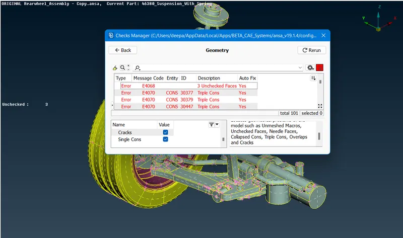
Fig: Before Applying Fix
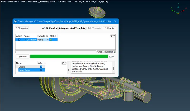
Fig: After Applying Fix
3) Setup Seperate Individual PID's for Various Assembly Parts:
Select all the assembly parts individually and assign PID to each of the selected parts by following Topo > Faces > Set PID.
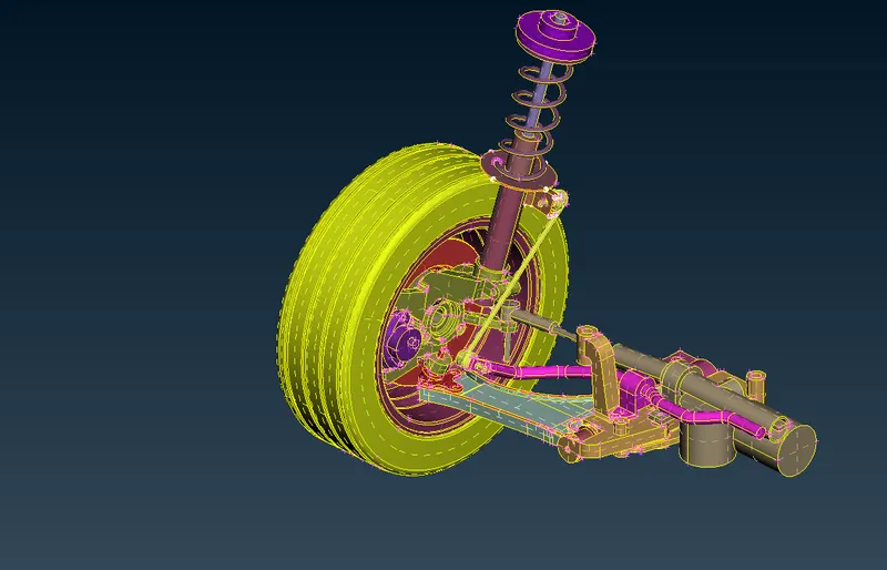
Fig: PID's Assigned
4) Mid Surface Extraction:
Check for the assembly parts having thickness less than 5mm and extract mid surface for those assembly parts. Here, offset option is used to extract the mid surface of wishbone part but other options like middle and automid can also be used for mid surface generation wherever possible.
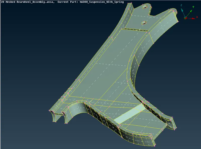
Fig: Wishbone
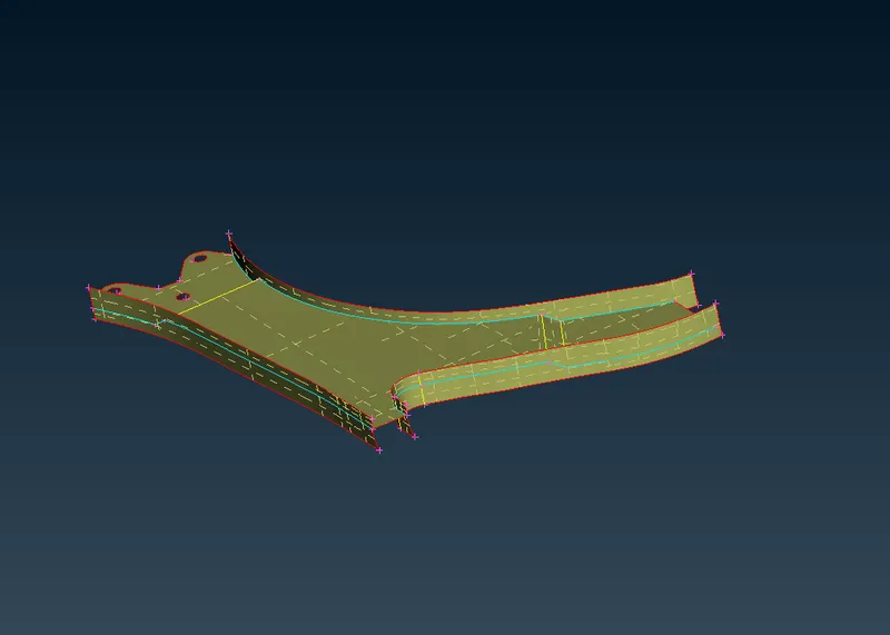
Fig: Wishbone Midsurface
5) Meshing of Various Assembly Parts:
Meshing of assembly parts are done using surface meshing, volume meshing and 2D meshing.
2D Meshing:-
2D meshing is done on mid surfaces of the parts having thickness less than 5mm and here, 2D meshing is performed for 3 parts whereas wishbone is meshed after taking mid surface with offset faces and other two parts are meshed using automatic middle surface mesh generator. The Quality criteria used for 2D meshing is shown in images below.
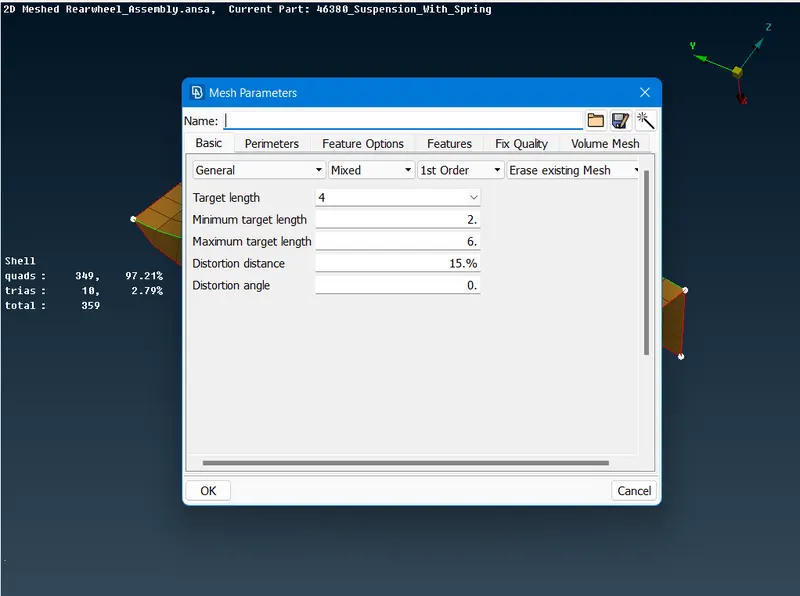
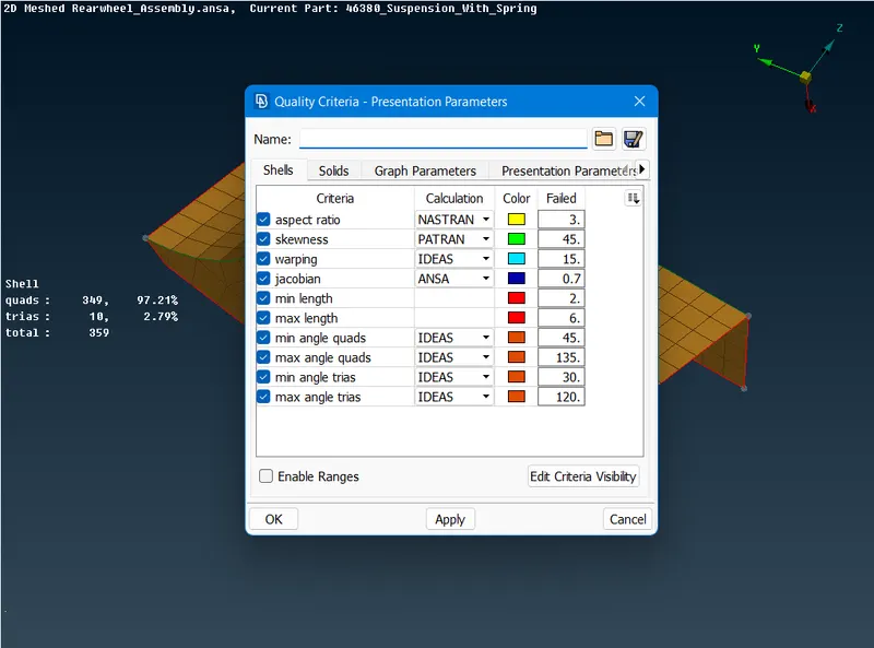
Fig: 2D Meshing Quality Criteria
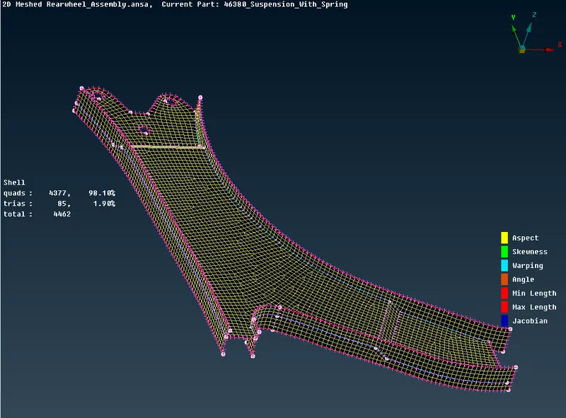
Fig: Wishbone Meshed
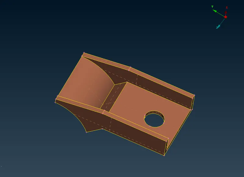
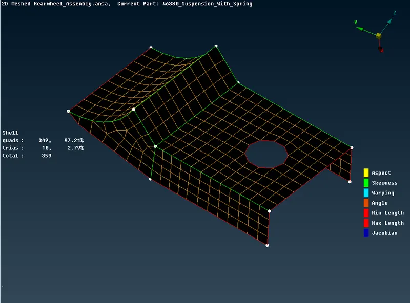
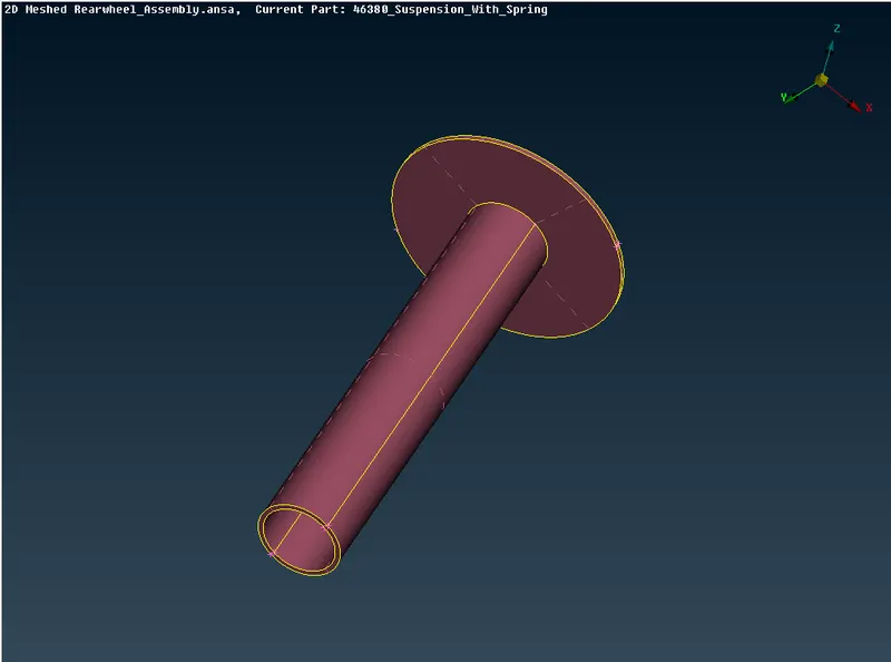
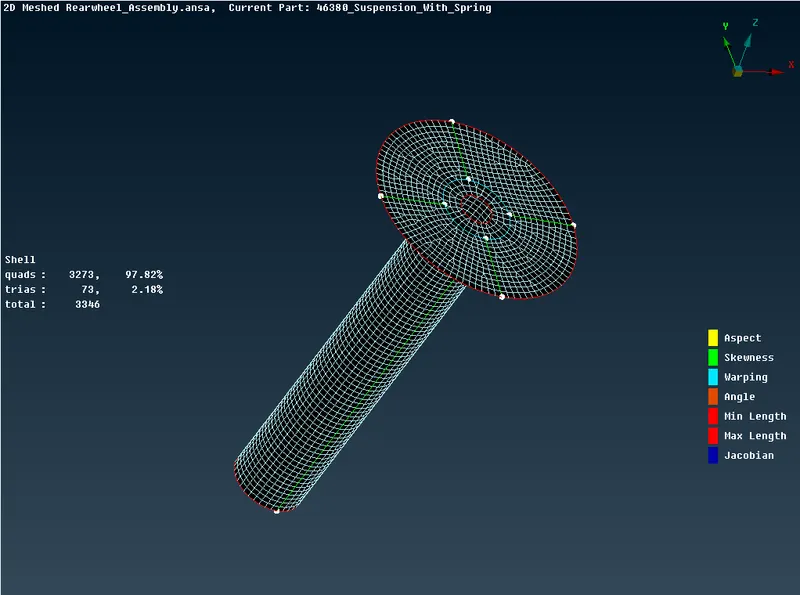
Fig: Before and After Casting Approach
Surface Meshing:-
Surface meshing is performed for parts having thickness larger than 5mm like Tyre, Rim and other parts. Components are meshed using tria and ortho trias elements with a target element length of 4 mm. Ortho Trias are generally used on features such as fillets, chamfers etc for better mesh capturing and tria elements are used for flat surfaces.
Surface Meshing of Tyre and Rim-
One can do mesh generation for tyre and rim either by meshing them manually using spot mesh or by batch mesh. Tyre and Rim Parts are Meshed using Batch Meshing. The advantage of batch meshing is that ANSA will do topological clean up automatically which is a time saving process. Even though sometimes we have to clear some errors manually after batch meshing also but overall it is a less time consuming process as compared to the manual meshing.
Firstly the part is set as a new part in model browser and then a new meshing Scenario is created. newly created part is then added to the part list so that batch meshing can be performed. now update the content which means the required mesh parameters and quality criteria are updated and then click on RUN to generate batch mesh.
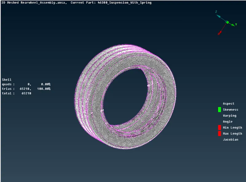
Fig: Meshed Tyre
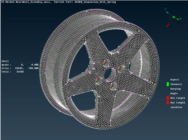
Fig: Meshed Rim
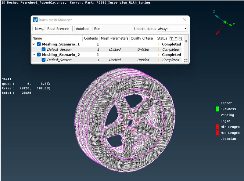
Fig: Batch Meshing Scenario
The Quality criteria used for surface meshing of tyre and rim is shown in images below.
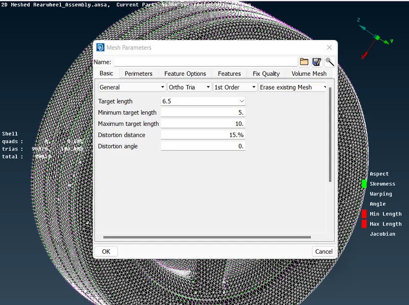
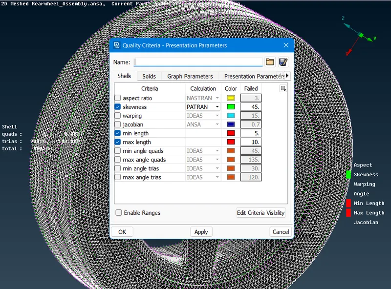
Fig: Surface Meshing Quality Criteria for Rim and Tyre
Surface Meshing of Other Parts-
Most of all the parts other than tyre and rim are also batch meshed and some are manually meshed using trias and ortho tria elements. The Quality criteria used for surface meshing is shown in images below.
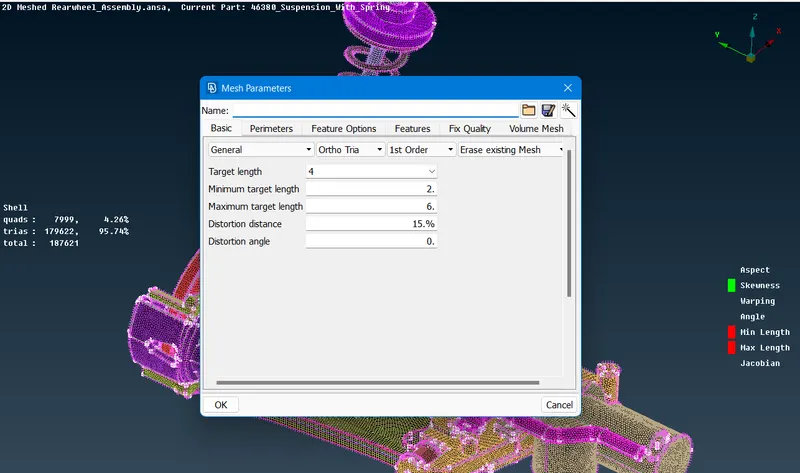
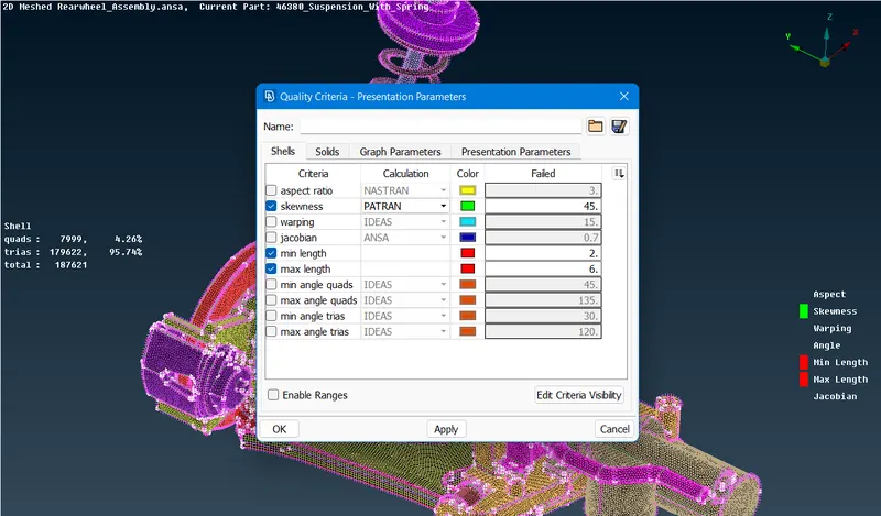
Fig: Surface Meshing Quality Criteria for Other Parts
Finally all the parts after surface meshing can be seen in image below.
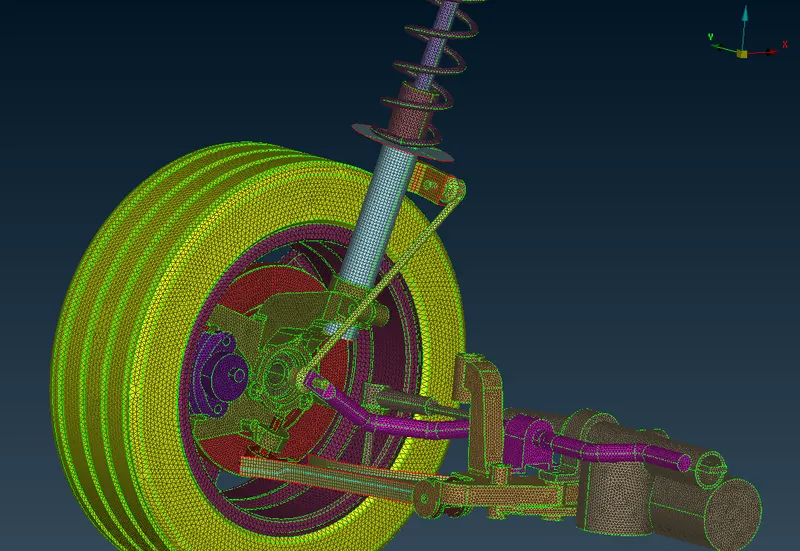
Fig: Surface Meshed Suspension Aseembly Model
Volume Meshing:-
After surface meshing, now we can head towards volume meshing. Volume meshing can be performed in ANSA only if it recognizes the geometry as a closed volume so we have to manually define individual closed volume out of the all surface meshed parts, also individual PID's are assigned to these closed volume. After listing the closed volume in volume section of the V.Mesh Module, go to Remesh option and mesh the part using Tetra Rapid or Tetra FEM volume meshing algorithms. The Quality criteria used for volume meshing is shown in images below.
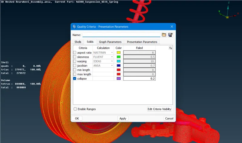
Fig: Volume Meshing Quality Criteria
Final volume meshed suspension assembly model can be seen in image given below.
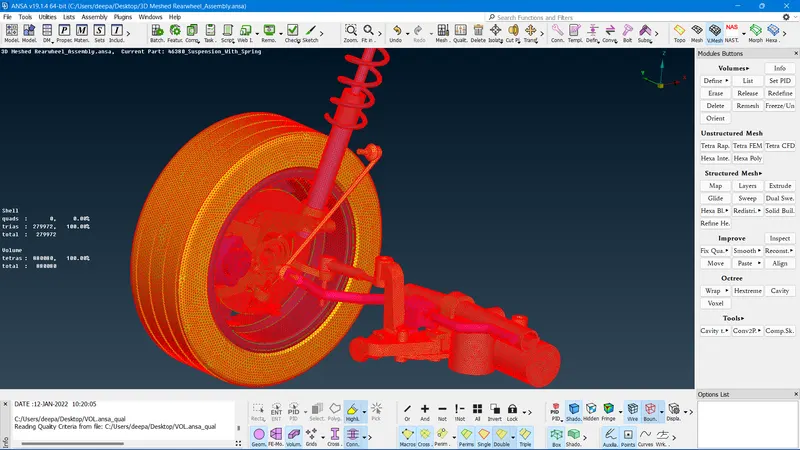
Fig: Volume Meshed Suspension Assembly Model
6) Connection Deployment:
After Meshing, connections has to be deployed between various assembly parts. Here, Cluster RBE2 connections, Bolt connections and weld connections are used.
Cluster RBE2 Connections-
Cluster RBE2 connections are used to connect few parts by using following method-
NASTRAN Deck > ELEMENTs > RBE2 > Many Nodes. Slect nodes to be connected and give confirmation to deploy the connection.
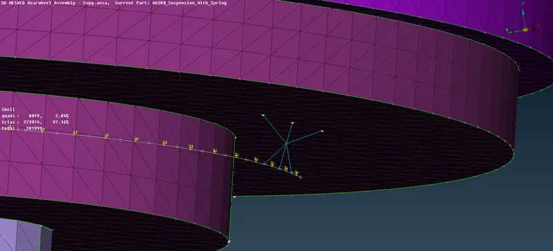
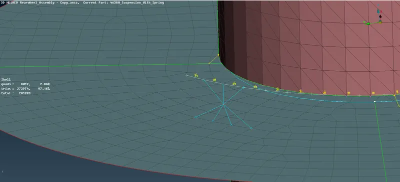
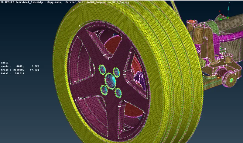
Fig: Cluster RBE2 Connections
RBE2 Connections with Two Nodes-
For RBE2 Two Nodes connections deployment, go to NASTRAN Deck > ELEMENTs > RBE2 > Two Nodes > Node Sets > Select first node group > Middle mouse click > Select second node group and give confirmation.
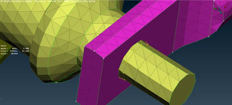
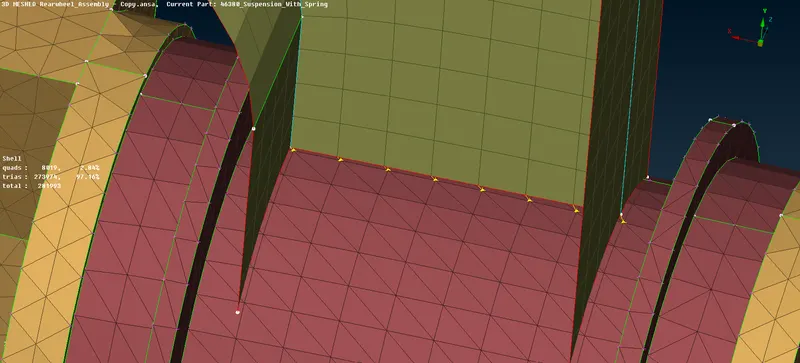
Fig: RBE2 Connections With Two Nodes Option
Bolt Connections-
Most of the connections used are bolt connections in this model although bolt connections can also be deployed by creating 3D points and converting them into a bolt connection and then using connection manager to realize them as a bolt connection but here, bolt connections are made simply by creating many node cluster RBE2 and then connecting each two of them with two node RBE2 elements as mentioned above.
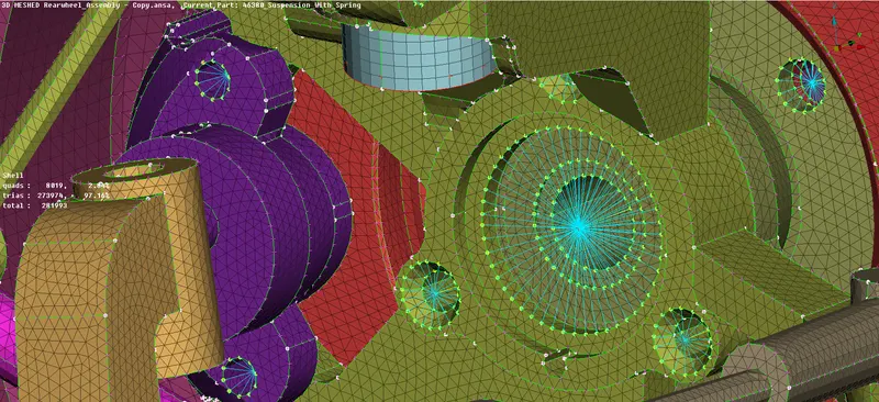
Fig: Bolt Connections
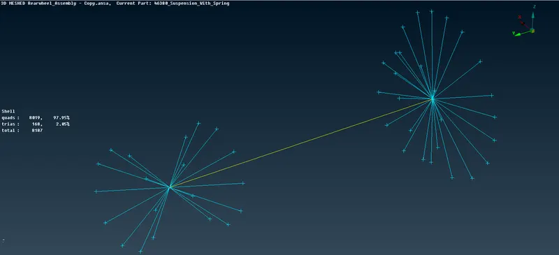
Fig: A Typical Bolt Connection
Seam Weld Connections-
Seam weld is generally a shell connection deployed between two surfaces. For generating seam weld connection first create a curve on the FE usiong Feat2Curve option. Now, convert this curve into seam weld using convert option. Then select the generated seam weld curve using connections manager. In the connection manager assign P1 and P2 for surfaces which are to be connected using seam weld. Create COG and Convert COG to seam welding, Use connections manager to generate Overlap-Shell element as a connection. After that enter all the required info and then click on apply and realize.
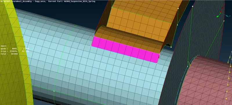
Fig: Seam Weld Connection
7) Use Transform Option:
After deploying all the connections, now we have to use transform option to create a mirror of the half assembly model on the other side using Transform > Copy > Select Entities > Symmetry > Mirror 3 points Plane.
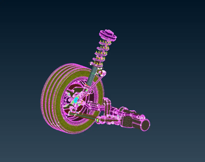
Fig: Before Transform (Half View)
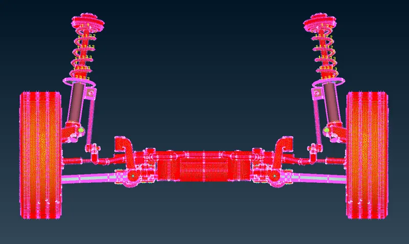
Fig: After Transform (Full View)
Final model with all the connections deployed can be seen in image below.
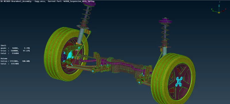
Fig: Final Suspension Assembly Model
CONCLUSION:
Successfully performed preprocessing on the suspension assembly model.
LEARNING OUTCOMES:
- Able to do topological cleanup.
- Assigned separate PIDs for different surfaces and volumes.
- Able to generate mid surface.
- Aware of all the quality criterias and mesh parameters during mesh generation. Learned how to improve mesh flow and remove trias to achieve better mesh flow.
- Understood concets regarding connections. Deployed different types of connections.
- Understood all the concepts regarding mid surface generation, volume mesh generation, meshing, connections used for NVH analysis in ANSA.