Project - 2 - Meshing on the suspension Assembly
AIM - For the given assembly, check for the geometrical errors and mesh with the given element Quality criteria. After meshing the component the thickness has to be assigned for mid surfaces. Use tetra elements to model non-uniform thickness components. Also, use connections where it's required.
PROCEDURE - Just like before our first step is to download the model and then perform topo and geometry cleanup on the model, but this time we have to go with a different way for better understanding we can divide our model into 3 different parts or cases, that we can discuss in detail down below
Part-1
In our first case, we have to go through different quality criteria i.e
Quality Criteria for Tria Elements (Tyre and Rim):
|
S.No |
Quality Criteria |
Value |
|
1 |
Target/Average length |
6.5 |
|
2 |
Minimum Length |
5 |
|
3 |
Maximum Length |
10 |
|
4 |
Skewness |
45 |
Common Quality Criteria for Tetra elements are:
|
S.No |
Quality Criteria |
Value |
|
1 |
Tet-collapse |
0.2 |
- Here we don’t discuss much meshing and all because that we already know we simply give a tria mesh over here because ortho tria make 90-degree angle so it might create element failure so use tria only in case of the tyre and rim .you can see how it look like when you apply to mesh on it.
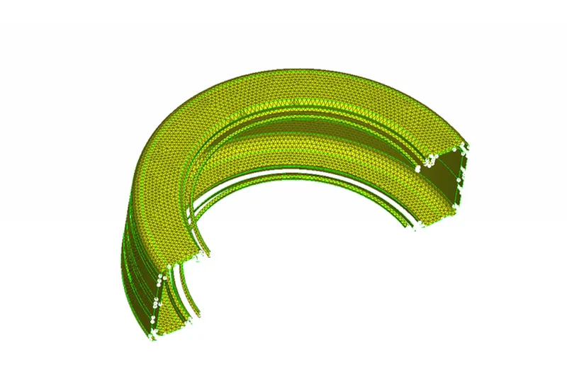
Fig 1. Tyre
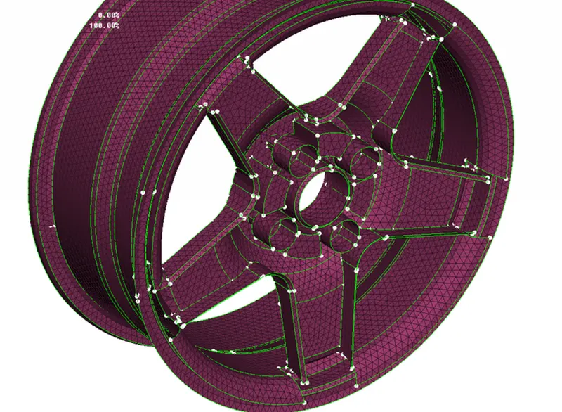
Fig 2. Rim
- After this, you have to define the volume for both parts and it appears like this in fig.3, fig.4
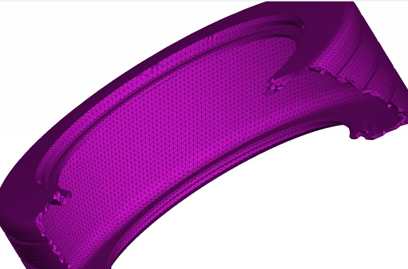
Fig 3. A tyre with solid volume
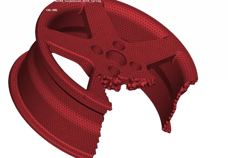
Fig 4. Rim with solid mesh
Part -2
Here we have to follow this quality criterion
Quality criteria for Mixed elements (For Midsurface only):
|
S.No |
Quality Criteria |
Value |
|
1 |
Target/Average length |
4 |
|
2 |
Minimum Length |
2 |
|
3 |
Maximum Length |
6 |
|
4 |
Aspect |
3 |
|
5 |
Warpage |
15 |
|
6 |
Skewness |
45 |
|
7 |
Jacobian |
0.7 |
|
8 |
Minimum Quad Angle |
45 |
|
9 |
Maximum Quad Angle |
135 |
|
10 |
Minimum Tria Angle |
30 |
|
11 |
Maximum Tria Angle |
120 |
- In this case, we have to take the mid of the component and then we perform meshing on it as per the given quality criteria so it looks like this in fig. 5
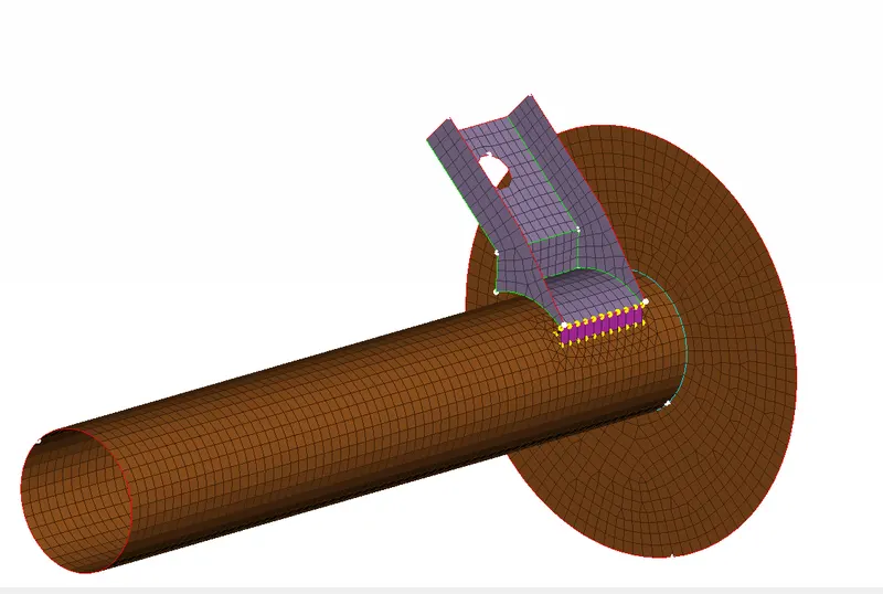
Fig. 5 Suspension sub-part mid surfacing and connection
- After assigning thickness to it, it looks like this in fig.6
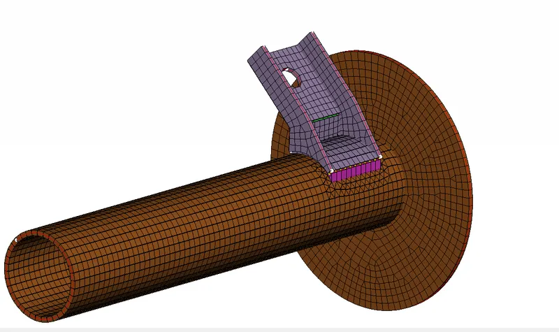
Fig. 6 Model with a thickness
Part-3
In this case, we have to follow these quality criteria
Quality criteria for Tria (For other components):
|
S.No |
Quality Criteria |
Value |
|
1 |
Target/Average length |
4 |
|
2 |
Minimum Length |
2 |
|
3 |
Maximum Length |
6 |
|
4 |
Skewness |
45 |
Common Quality Criteria for Tetra elements are:
|
S.No |
Quality Criteria |
Value |
|
1 |
Tet-collapse |
0.2 |
Here we have to perform the same method as we perform in case 1 but in this case, we have to follow different quality criteria. In this model, we have lots of components but here we demonstrate the only one just for an overview that how it looks like so when we apply to mesh on it look like this as shown in fig.7
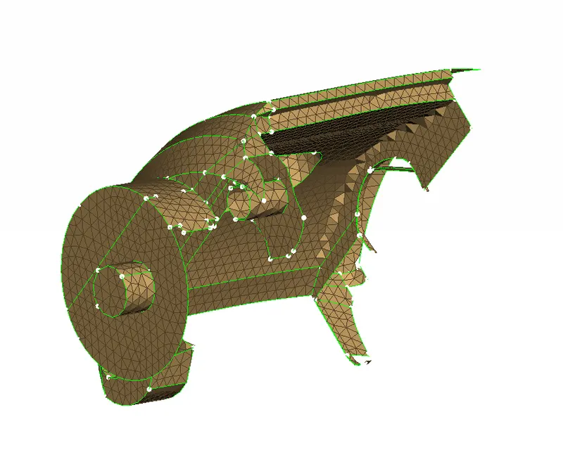
Fig. 7 Model with mesh
- After defining the volume on the model, it looks like this as shown in fig.8
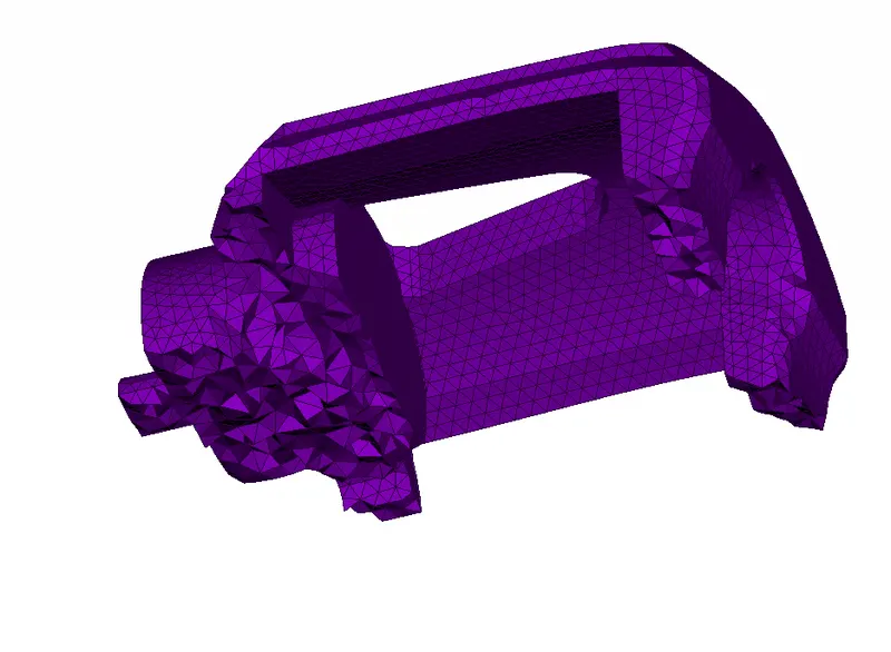
Fig. 8 Model with solid mesh
- When we talk about connections as for now I give two connections that are RBE2 and Seam weld on it that you can see in fig.9,10
Fig. 9 Seam weld Connection
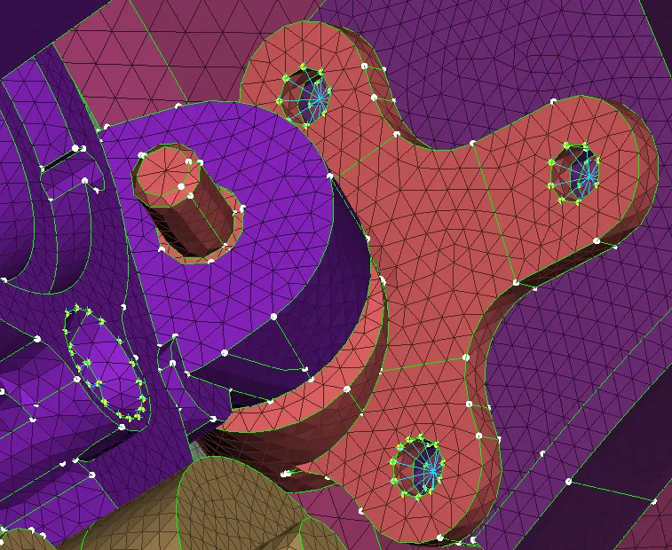
Fig. 10 Bolt Connection
- One more connection that we give to the spring is CBAR
That is present under the NASTRAN deck in the element module after doing this we have to go to the quality criteria tab and switch on the line element cross-section then tick on as solid, so it will look like this as shown in fig.11
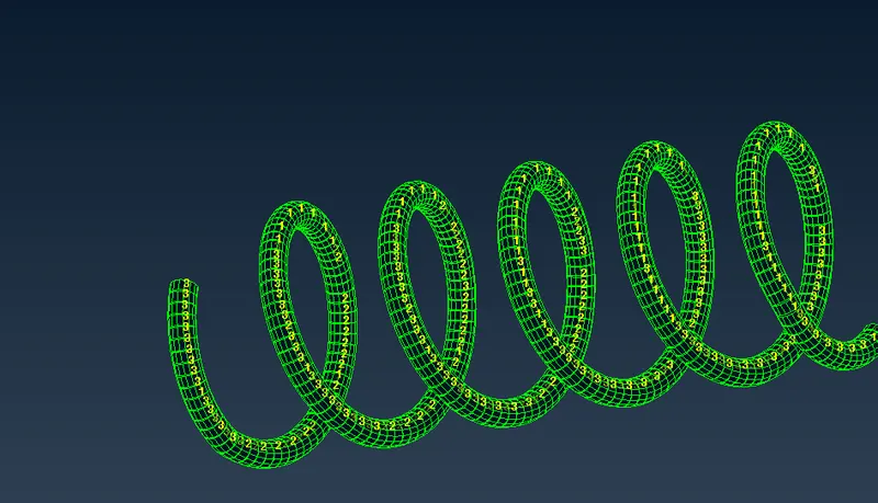
Fig. 11 CBAR
- In the end, our model looks like this (fig.12)
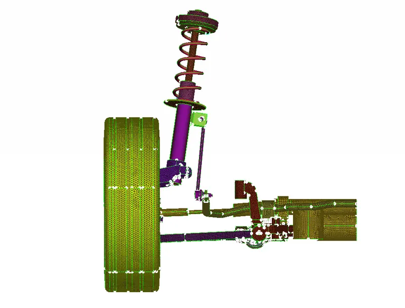
Fig.12 Model with mesh
- After giving symmetry finally our suspension look like this in fig.13
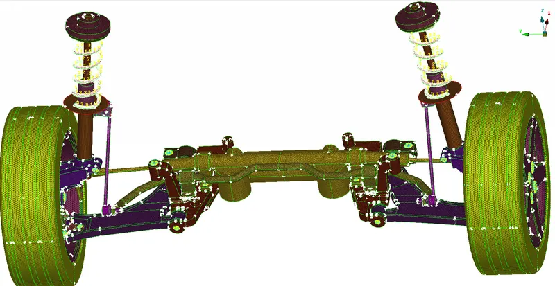
Fig.13 Model with mesh
LEARNING OUTCOMES - In this model, I learned solid and shell meshing and connection as well.
CONCLUSION - As per the given quality criteria, we got our final result.
Model Drive Link: https://drive.google.com/file/d/1qlgxMWQzQRlvJlFHH6diCEa4H3HGc-JN/view?usp=sharing