Project - 2 - Meshing on the suspension Assembly
AIM: Meshing and implementing connections to the car rear suspension model.
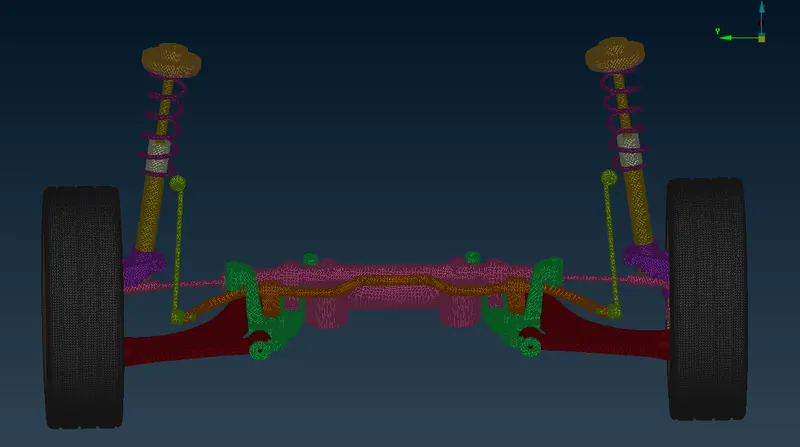
ABSTRACT: In this project, I have taken a half section of a car rear suspension system where I will perform meshing on different components with 3D, 2D & 1D elements. Also, I will implement the connections to the areas required. The components with a uniform thickness of less than 5 mm are captured by the mid-surface technique (2D-elements), spring with 1D elements, and rest are captured using 3D elements(Tetra elements).
METHODOLOGY: To capture the geometry we need to follow these steps.
- Import geometry & Topological cleanup
- Parts segregation under different property ID
- Quality parameter and Mesh parameter setup as per the requirements given
- Construction line adjustment and defeaturing
- Mid-surface extraction if the components with a uniform thickness of less than 5 mm
- Shell meshing and mesh correction.
- Volume definition and 3D mesh generation for other than mid-surfaced components.
- Implementation of connections at required areas.
QUALITY PARAMETERS:
These are the following quality criterion required to be followed in this project:
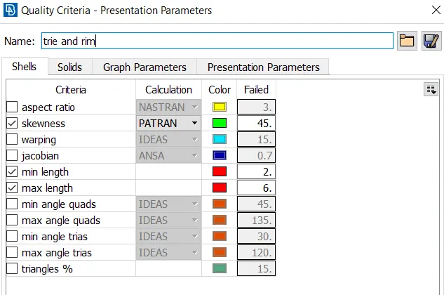
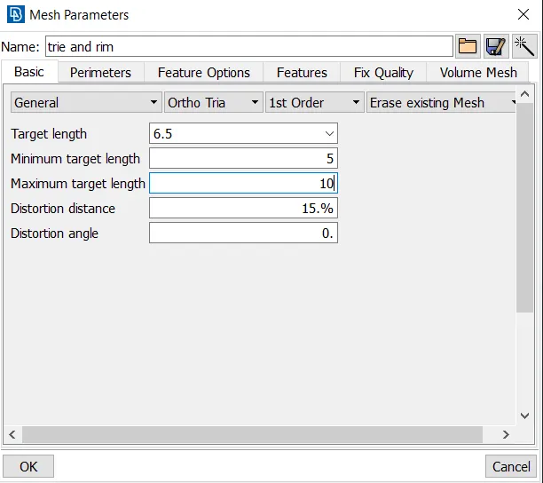
Tyre and Rim (Tria):
|
S No. |
Quality criteria |
Value |
|
1 |
Target/Average length |
6.5 |
|
2 |
Minimum length |
5 |
|
3 |
Maximum length |
10 |
|
4 |
Skewness |
45 |
For mid surface only (Mixed):
|
S No. |
Quality criteria |
Value |
|
1 |
Target/Average length |
4 |
|
2 |
Minimum length |
2 |
|
3 |
Maximum length |
6 |
|
4 |
Aspect |
3 |
|
5 |
Warpage |
15 |
|
6 |
Skewness |
45 |
|
7 |
Jacobian |
0.7 |
|
8 |
Minimum quad angle |
45 |
|
9 |
Maximum quad angle |
135 |
|
10 |
Minimum tria angle |
30 |
|
11 |
Maximum tria angle |
120 |
For all other components (Tria):
|
S No. |
Quality criteria |
Value |
|
1 |
Target/Average length |
4 |
|
2 |
Minimum length |
5 |
|
3 |
Maximum length |
10 |
|
4 |
Skewness |
45 |
Tetra elements (3D):
|
S No. |
Quality criteria |
Value |
|
1 |
Tet collapse |
0.2 |
INTRODUCTION
Vehicle Suspension System
Suspension has been an essential component of automobiles. The rear suspension of a vehicle performs the same general function as front susprnsion, but the specific construction is typically quite different. The ideal suspension for a vehicle depends a lot on the vehicle body style and performance requirements. The most basic purpose of a susupension system are to prevent the body of a vehicle from hitting the ground and to keep the tires in connect with the road.
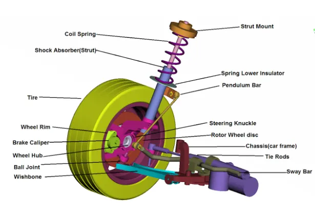
The suspension system contains three major parts: a structure that supports the vehicle’s weight and determines suspension geometry, a spring that converts kinematic energy to potential energy or vice versa, and a shock absorber that is a mechanical device designed to dissipate kinetic energy.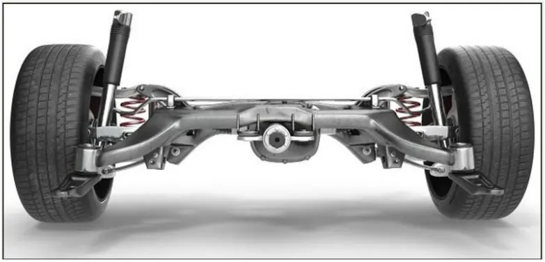
Types of Suspension System
1) Independent suspension system
This system means that the suspension is set-up in such a way that allows the wheel on the left and right side of the vehicle to move vertically independent up and down while driving on an uneven surface. A force acting on the single wheel does not affect the other as there is no mechanical linkage present between the two hubs of the same vehicle. In most of the vehicles, it is employed in front wheels.
This type of suspension usually offers better ride quality and handling due to less unsprung weight. The main advantages of independent suspension are that they require less space, they provide easier steerability, low weight, etc.. Examples of Independent suspension are
- Double wishbone
- Macpherson strut
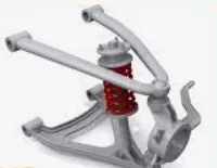
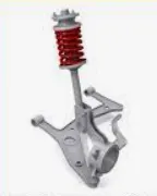
Double wishbone Macpherson strut
2) Dependent Suspension System
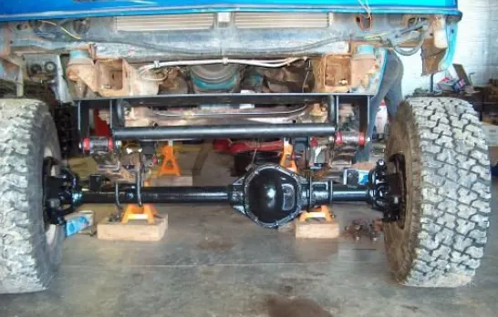
IN Dependent Suspension there is a rigid linkage between the two wheels of the same axle. A force acting on one wheel will affect the opposite wheel. For each motion of the wheel caused by road, irregularities affect the coupled wheel as well. It is mostly employed in heavy vehicles. It can bear shocks with a great capacity than independent suspension. Example of this system is
- Solid Axle
3) Semi-Dependent Suspension System
This type of system has both the characteristics of a dependent as well as independent suspension. In semi-independent suspension, the wheel move relative to one another as in independent suspension but the position of one wheel has some effect on the other wheel. This is done with the help of twisting suspension parts. Example of semi-independent is
- Twisted Beam
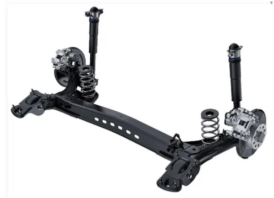
The difference between independent and dependent suspension system can be easily observed in the figure shown below:
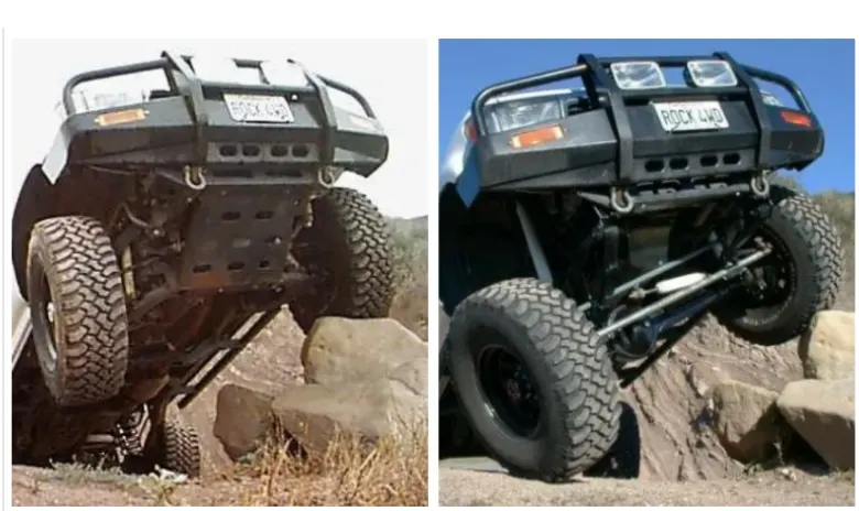
Dependent Suspension System Independent Suspension System
COMPONENTS OF A CAR SUSPENSION SYSTEM:
PROCEDURE:
Import geometry & Topological cleanup
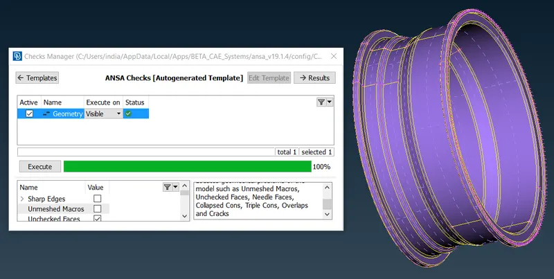
First of all, we need to import the CAD model into the ANSA interface. Once we are done loading the file do a TOPO over the full geometry. Then go for a geometry check and fix all the topological errors to proceed to the next step.
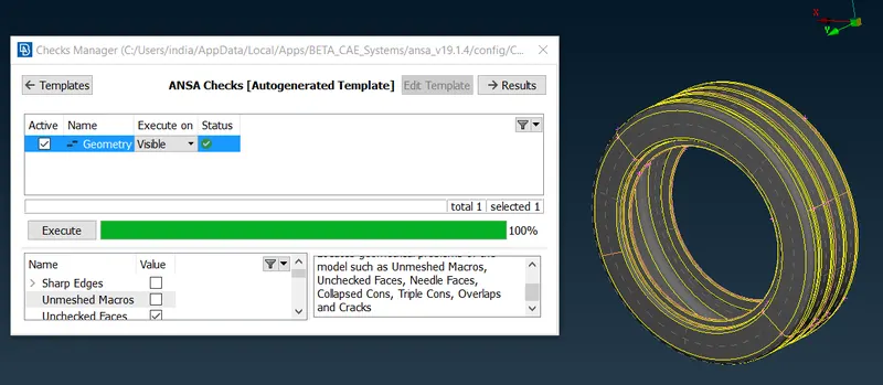
Parts segregation under different property ID
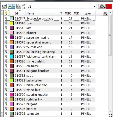
Once we have fixed all errors we can segregate different parts under property ID so as to proceed part by part which helps to expedite the process of pre-processing
Quality parameter and Mesh parameter setup as per the requirements given
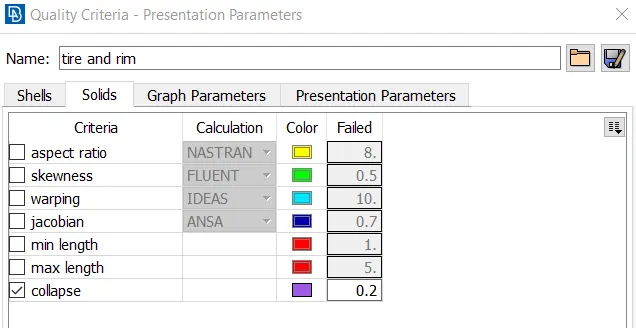
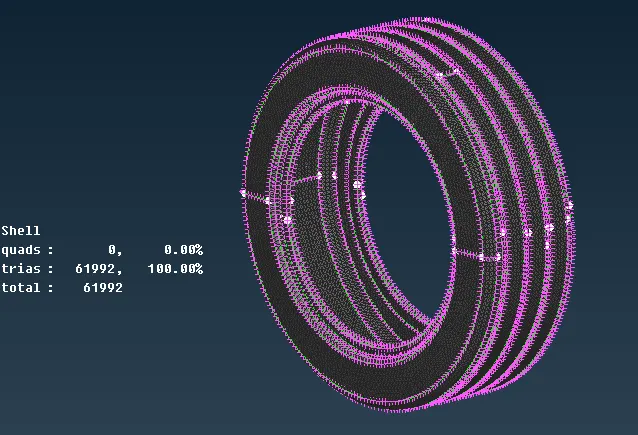
Set the quality and mesh parameter as given for Tire and Rim.(ortho Tria & Tria)
Set the solid quality parameter for the Tetra element collapse value 0.2
Construction line adjustment and defeaturing
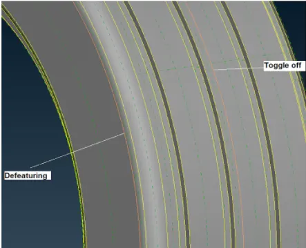
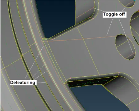
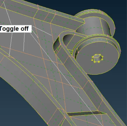
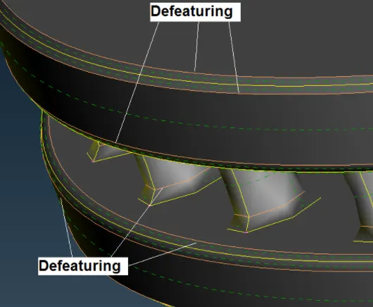
So as to capture the component properly we need to defeature and toggle off few construction lines and check geometry before going for meshing the component. Few of the areas are shown below:
Mid-surface extraction if the components with a uniform thickness of less than 5 mm
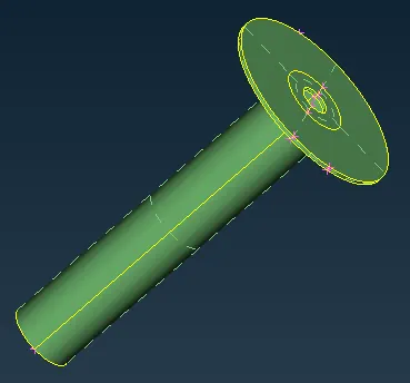
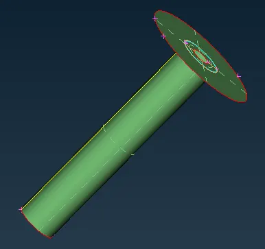
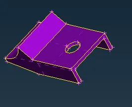
There are only 2 parts that have a length less than 5 mm(uniform thickness) and for those, we will go with the mid surface extraction strategy.
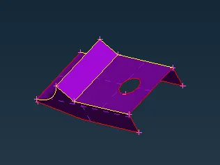
Shell meshing and mesh correction.
1) Tire and Rim
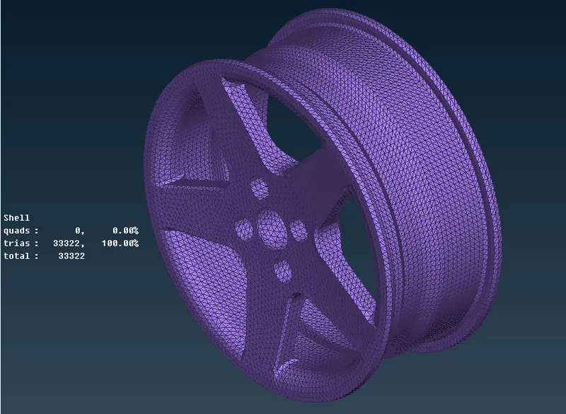
2) steering knuckle
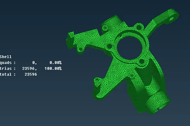
3) Wheel Hub and
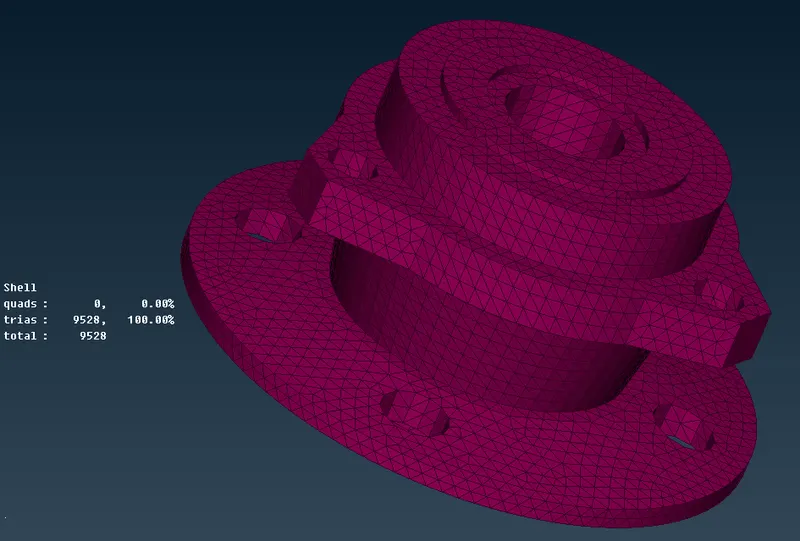
Volume definition and 3D mesh generation for other than mid-surfaced components.
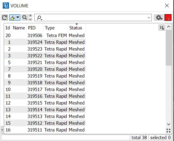
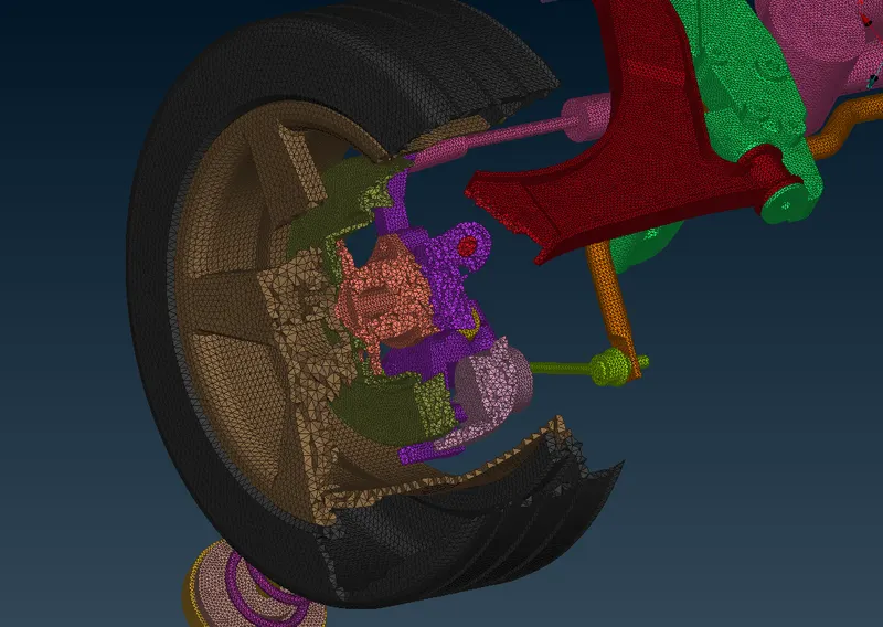
The next step we need to do is define them volume and generated Tetra elements through the volume but before defining them on the list we need to make sure the part is properly meshed and closed. Also, the part should not contain any overlapping surface. Define them one by one and set different PID type Solid as shown below figure. I have used Rapid Tetra mesh algorithm to auto-generate the Tetra element inside the volume.
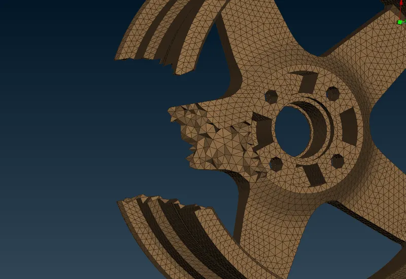
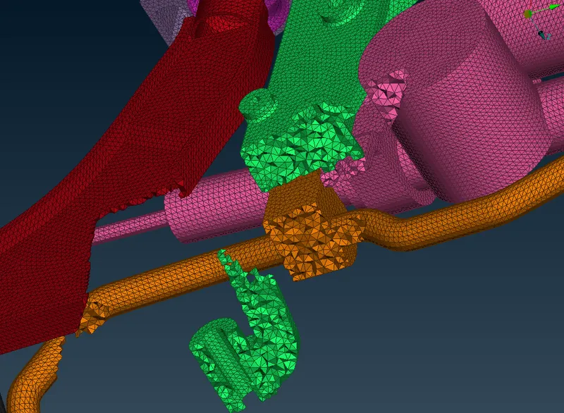
There are some section view illustrating Tetra solid element inside the volume

CONNECTIONS:
Implementation of connections at required areas.
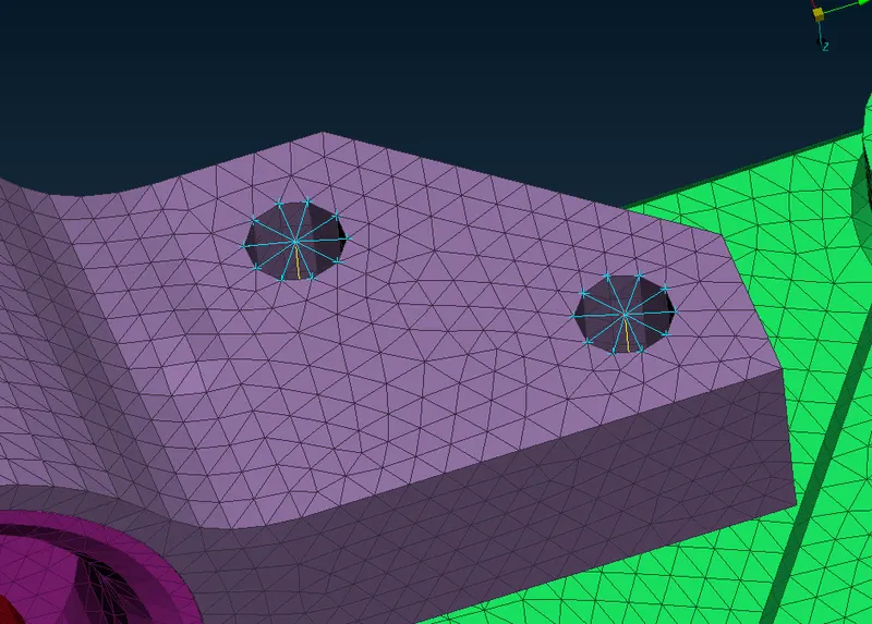
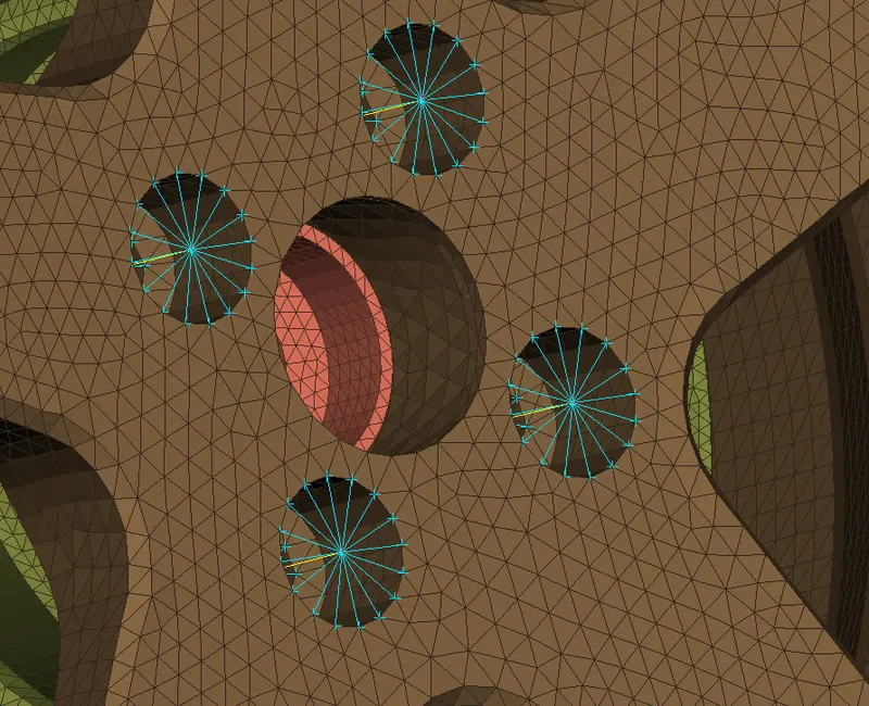
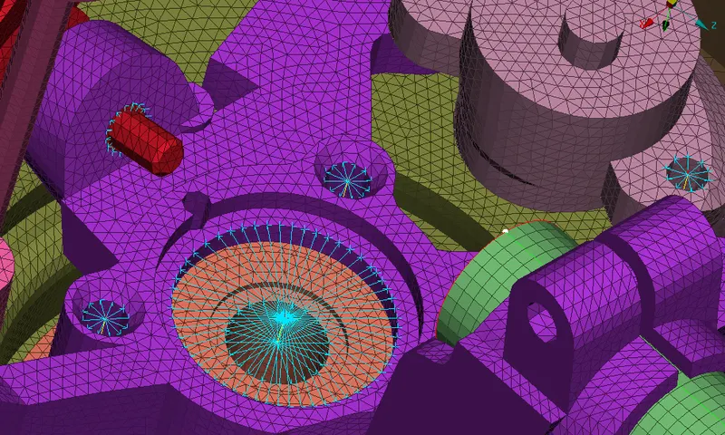
There are specific areas that need connections representing bolt, weld, and rigid connections. In the below figures attached it can be easily seen where and why these connections required.
Cluster or Spider RBE2: This connection is used when a manual bolt connection must be deployed between two or more surfaces.
- For automatic bolt connection one must follow these steps, create COG for the hole a COG is basically a 3D point, convert this 3D point to bolt, noe open connection manager and select the bolt symbol which has created in earlier step. Then assign P1, P2, P3 and select FE type as Bolt and give the required values and constraints and click apply and then realize the connection.
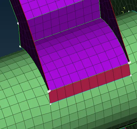
Seam weld:
- Seam weld is generally a shell mesh connection deployed between 2 surfaces.
- For generating seam weld connection first create a curve on a edges of FE.
- Now, connect this curve into seam line using convert option.
- Then select the generated seam line using connections manager and assign P1, P2, P3 and select FE type as overlap shell and give the required values and constraints and click apply and then realize the connection.
Seam weld:
TRANSFORM:
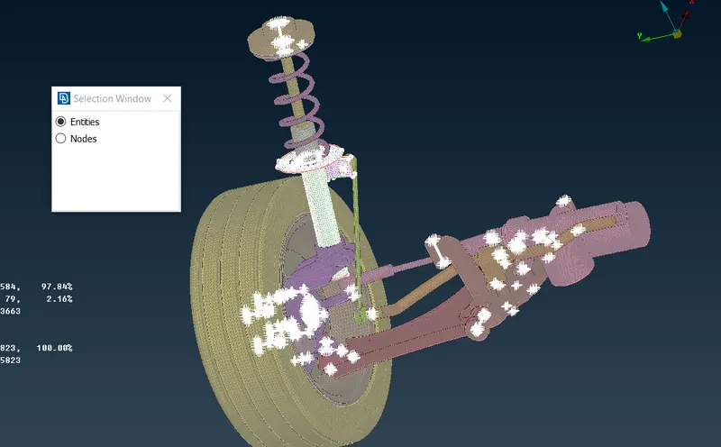
After completing mid surface generation, surface mesh, volume mesh and connection use transform option in order to create exact mirror of the model on the other side.
Go to transform and select all the entities including connections to generate exact replica of the model on the other side.
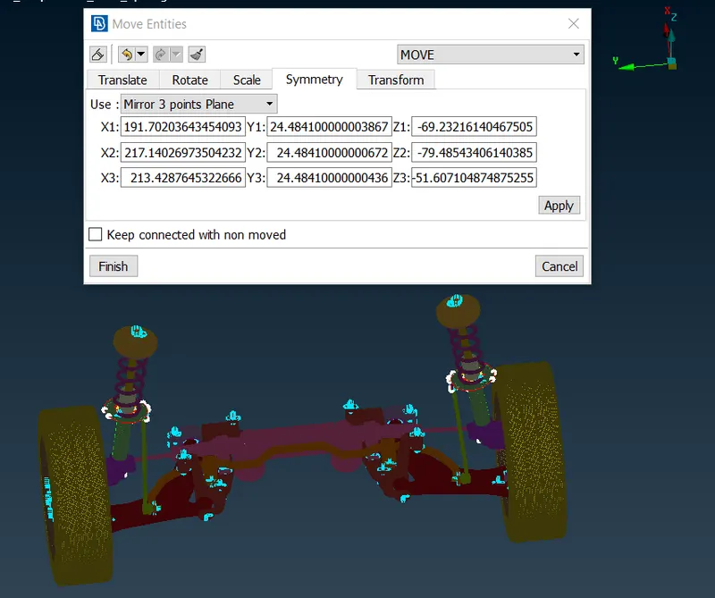
Now use symmetry panel and use mirror 3 points plane option and select 3 points on the edge. These 3 points represent all the 3 coordinates(x, y, z). This helps all the entities to transform on the other side.
OUTPUT:
CONCLUSION:
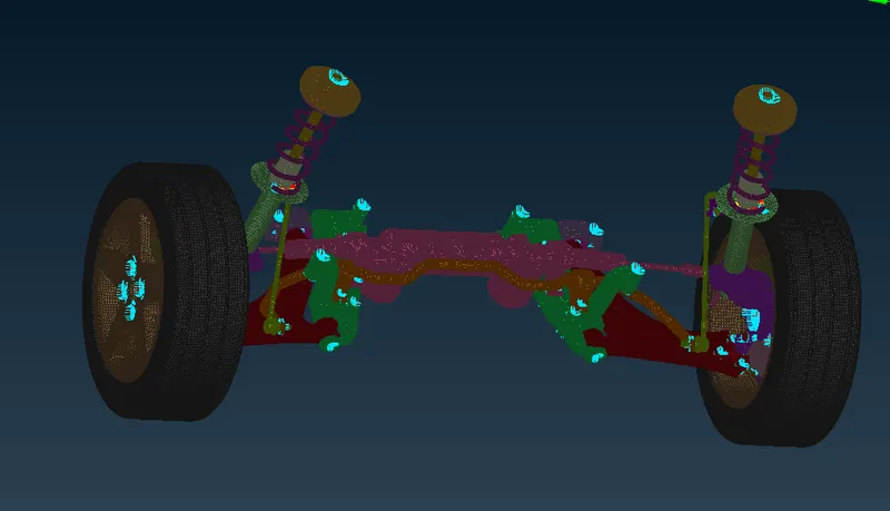
In this project, I have generated mid surfaces, shell mesh and volume mesh using different options available in ANSA. Successfully applied different quality criteria and mesh parameters for different parts and cleared off elements during mesh generation. All the components of a suspension system are captured quite decently with solid elements(Tetra) and shell element (Quad+Tria) as per the quality requirements. The sufficiently required connections are given with the RB2 cluster, two-node RB2 and seam weld. All tetra element under the volume meshing (3D) free from any Tetra collapse. The curved areas were mainly captured with the ortho Tria element during shell meshing on solid objects which helped to capture the feature correctly. The meshed final model has a smooth surface free from any dip or kinks and can be considered further processing.
LEARNING OUTCOME:
- Geometry check and cleanup.
- 1D, 2D(shell), and 3D(solid) meshing.
- Implementation of connections.
- Car suspension system components and their purpose.
Link: https://drive.google.com/file/d/1W9gSvPIll7qmtluwC-J3f_A0caVcgpDI/view?usp=sharing