Project - 2 - Meshing on the suspension Assembly
AIM: To mesh the given model with mixed elements whose thickness is less than 5mm and using Tria element to mesh whose thickness is greater than 5mm.
PROCEDURE:
Step1: To import the given model in ansa format.
Step2: To check for gemotrical issues.
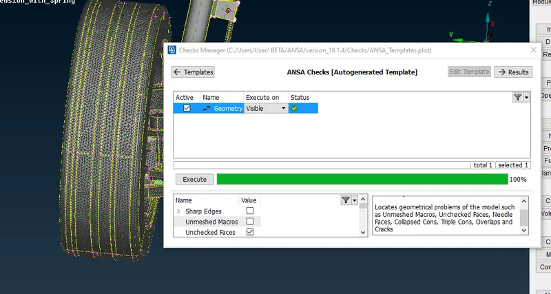
- No geometrical error found
Step3: Using casting option to the component where the thickness is less than 5mm.
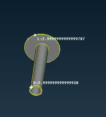
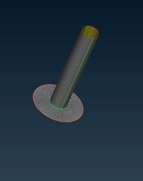
- Isolating the component to be casted Topo>midsurface>casting for meshing the surface using mixed element
Step4: Using surface meshing for the component whose thickness is less more than 5mm and meshing the elemets using tria elements to capture the elemets better.
- Isolating the tyre an giving the quality criteria and mesh parameter as per given.
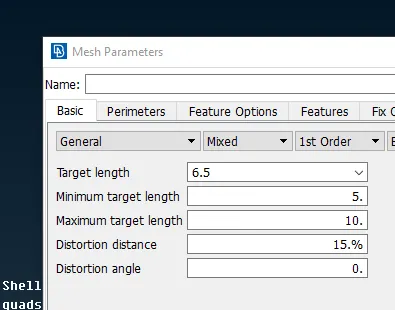
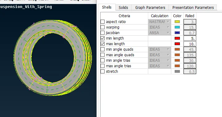
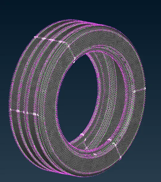
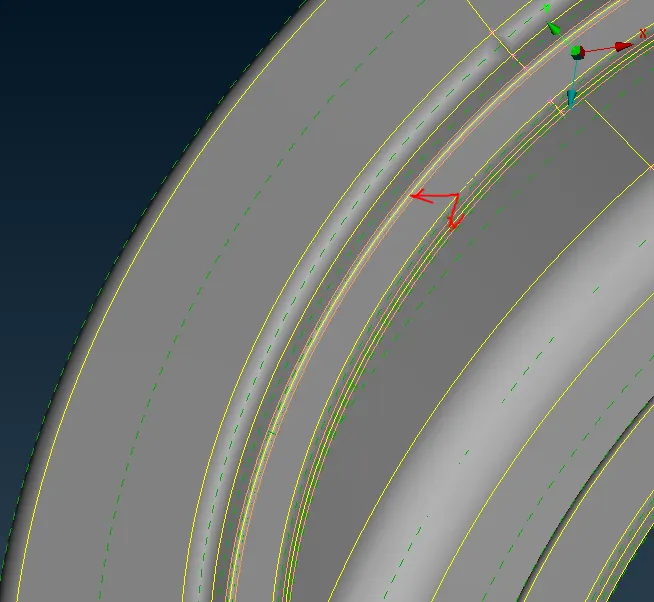
- Generating the mesh using tria elements, Mesh deck> mesh generation> best, using dash command to caputure peak of the fillet and eleminate the minimum length criteria Topo deck>dash>divide faces>join macros to get the middle cut.
- To generate the volume mesh by defining the volume for the tyre V.Mesh deck >define.
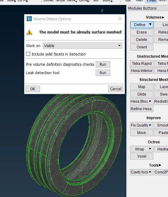
- Generating the volume by V.Mesh deck>tetra Fem>volume.
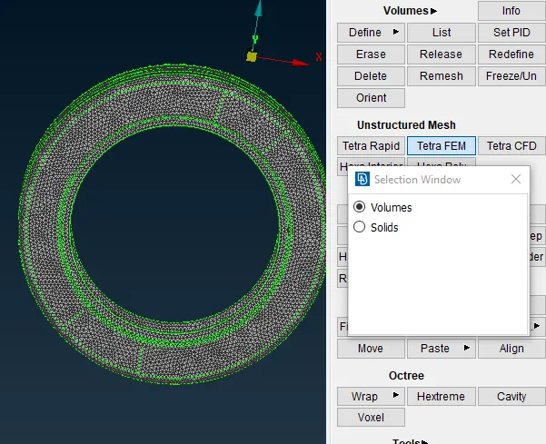
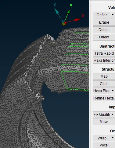
- Using V.Mesh deck>improve>fix quality to remove the Tet collapse element failure.
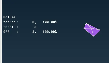
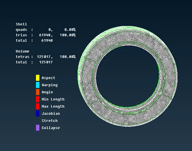
- Following the same procedure for the rest of the parts and also assigning quality criteria as well as mesh parameter.
Step5: To generate the elements for coil springs.
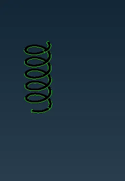
- Using curves middle option to generate the coil spring, Nast deck>element>cbar>5mm as the radius od the spring.Enabling the draw element line as solid.
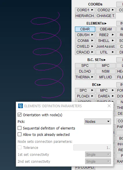
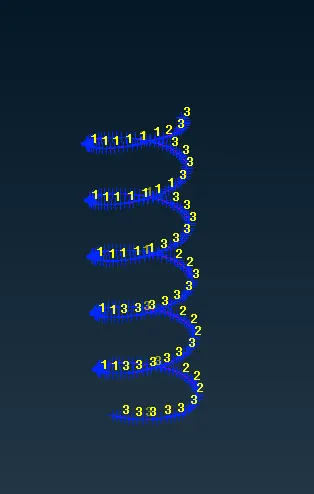
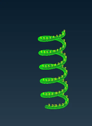
- Using seam weld for connecting two elements, Topo deck>curves>cons to curve
- Converting curves to seam weld , using connection manager to establish seam weld.
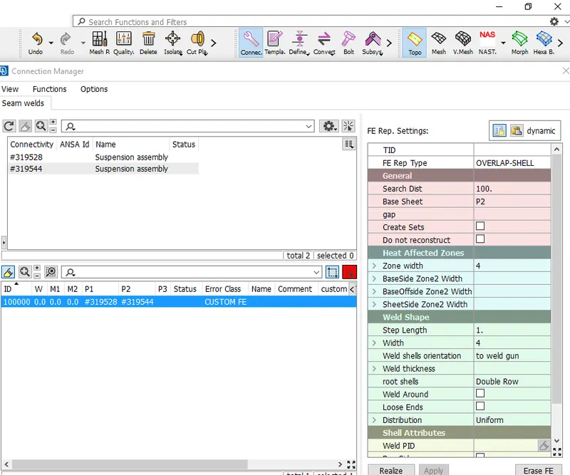
- Selecting FE type as Overlap-Shell inorder to weld the parallel surfaces.
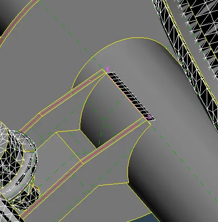
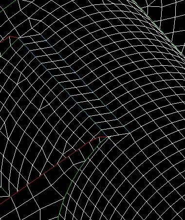
- Using bolt representation for tyre connection.
- Nastran deck>RBE2>Many node elements similarly creating the cluster element on the opposite side, Nastran deck>RBE2>Two node elements selecting both the master node of cluster element to represent the bolt
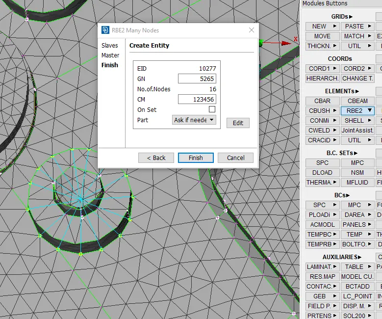
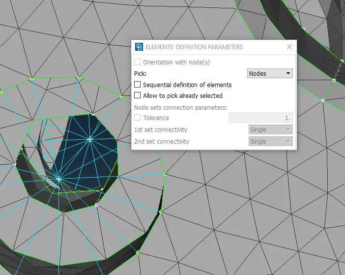
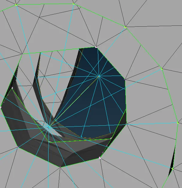
- Following the same procedure for the rest of the bolt representation.
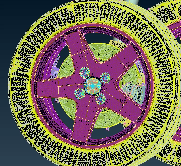
Step6: Using transform option to complete the rearwheel assembly.
- Transform>entity> making box section> Symmetry window>seleting the 3 points to mirror the entity.
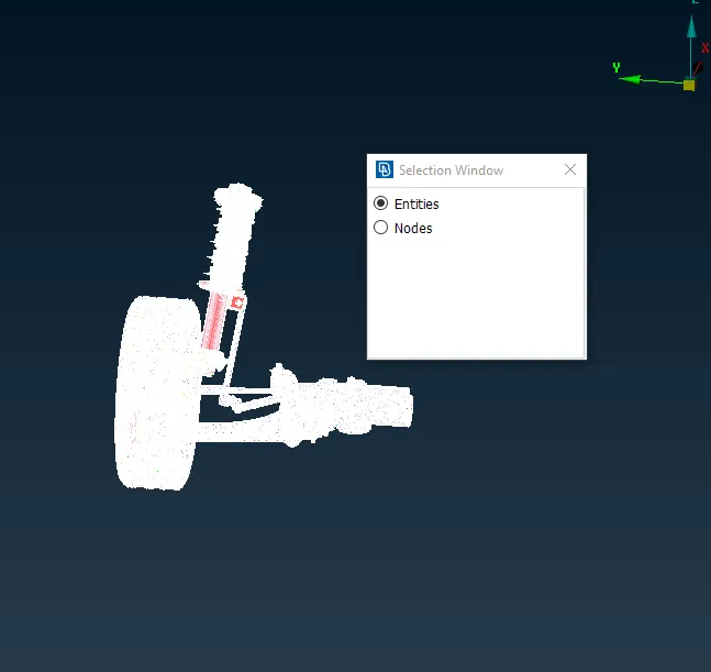
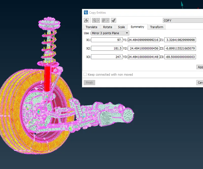
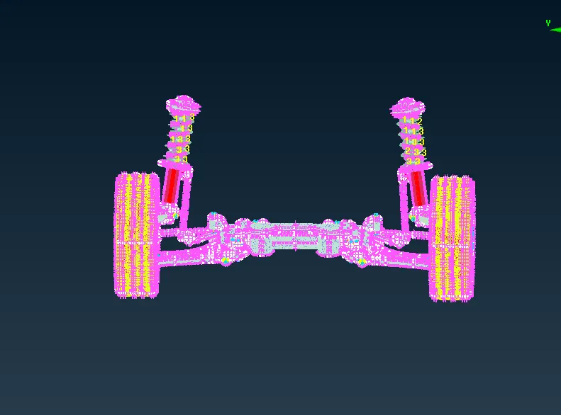
- The rear wheel assembly is complete.
LEARNING OUTCOMES:
- Learned how to mesh appropriatly depending on the thickness of the components.
- Learned how represent bolt connections.
- Learned how to establish seam weld connection.
- Learned how to fix tet collapse error in volume mesh.
- Learned how to generate volume mesh.
- Learned how to use Dash command to capture the fillet region with minimum steps.
- Learned how to mirror the model using symmetry option.
CONCLUSION:
Meshed the given model with suitable elements depending on the thickness of the components and as per the given quality criteria and mesh parameter.