Project - 2 - Meshing on the suspension Assembly
AIM :
To check for geometrical errors and to segregate the uniform and non-uniform thickness parts and to assign PID's for those. And to midsurface and 2D mesh the uniform thickness parts under the given quality criteria and for non uniform thickness parts the surface 2D meshing is done and 3D tetra mesh is also done under the given quality criteria. Finally assigning appropriate connectors at the required connecting areas.
PROCEDURE :
- Initially the given component Rear Wheel Assembly is imported in ANSA window and checked for any geometrical errors. If any geometrical errors are present they are fixed using the suitable method.
- The perimeter length and macro length of the geometry is assigned and the thickness of the geometry is measured at various regions. Thus the uniform and non-uniform thickness parts are segregated.
- The quality criteria and mesh parameters are given as input in the respective dropdown box. The geometry is once again checked for geomtrical errors by using the topo option.
- The parts with less than 5mm uniform thickness are to be midsurfaced and 2D surface meshed. The non-uniform thickness parts are 2D meshed with tria elements and then tetrameshed with a tetcollapse of 0.2.
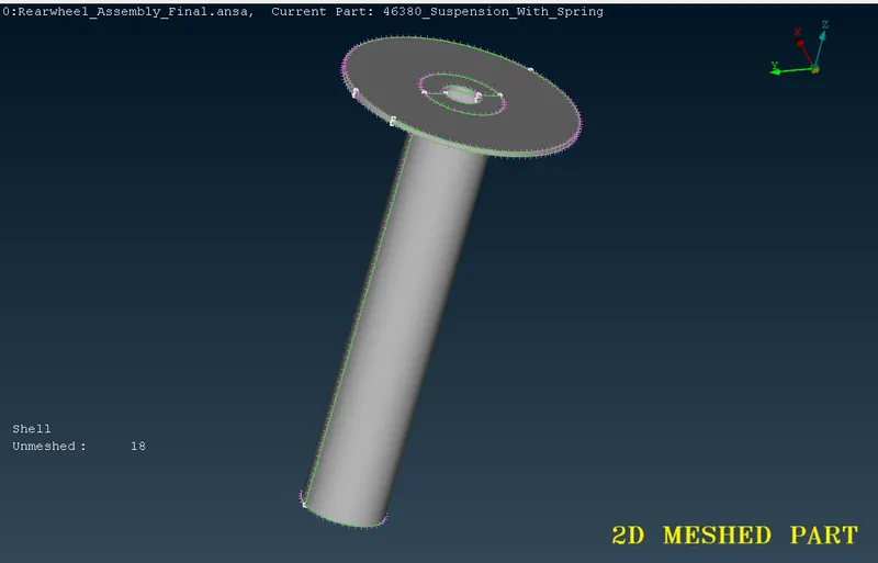
- The spring in the suspension model is represented using CBAR elements and for that middle curve for the spring is created and COG is created for the spring. Later in the Nastran deck the curve is represented as CBAR elements with a element length of 3mm and radius of 5mm.
- For the spring to be represented as solid, the line elements cross-section is represented as solids in the quality criteria panel and thus the CBAR elements are displayed as follows
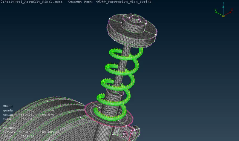
- In general as it is a complicated model, the meshing is done by differentiating the model into different PID's and the meshing is done by one after the other PID's. Thus the meshing is done for the entire model.
- For the purpose of assigning thickness to the midsurfaced parts, the thickness is measured initially in the CAD model and the same is assigned to the surface mesh. After it the connectors are to be deployed in the model at various regions and it's suggested to have rigid elements as connectors in the model.
- Thus the bolt connectors and seam weld are represented using RBE2 FE type and the connectors are checked for proper realization in the model.
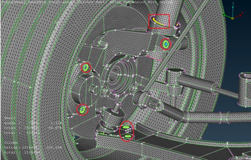
- Therefore the given model is done for meshing and assigning connectors and thickness.
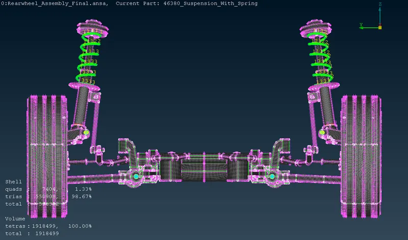
CAD MODEL IMAGES :
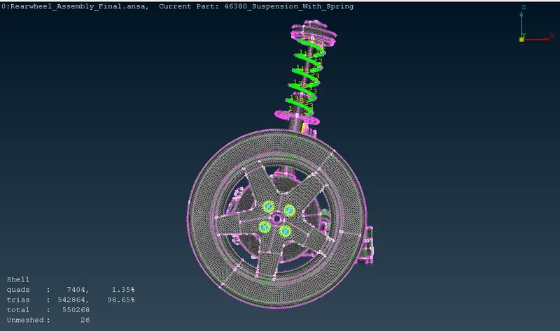
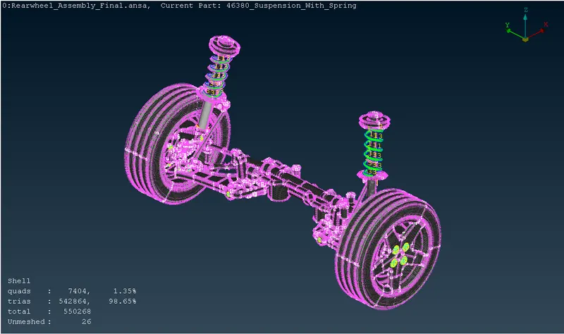
CONCLUSION :
Therefore the given model is checked for geometrical errors and the uniform and non-uniform thickness parts are separated and PID's are assigned. And midsurfacing of uniform thickness parts and 2D meshing of those parts under the given quality criteria and for non uniform thickness parts the surface 2D meshing and 3D tetra meshing is also done under the given quality criteria. Finally appropriate connectors at the required connecting areas are also deployed successfully.