Project - 2 - Meshing on the suspension Assembly
Aim - To mesh the given model using different meshing techniques and giving appropriate connections.
Model - 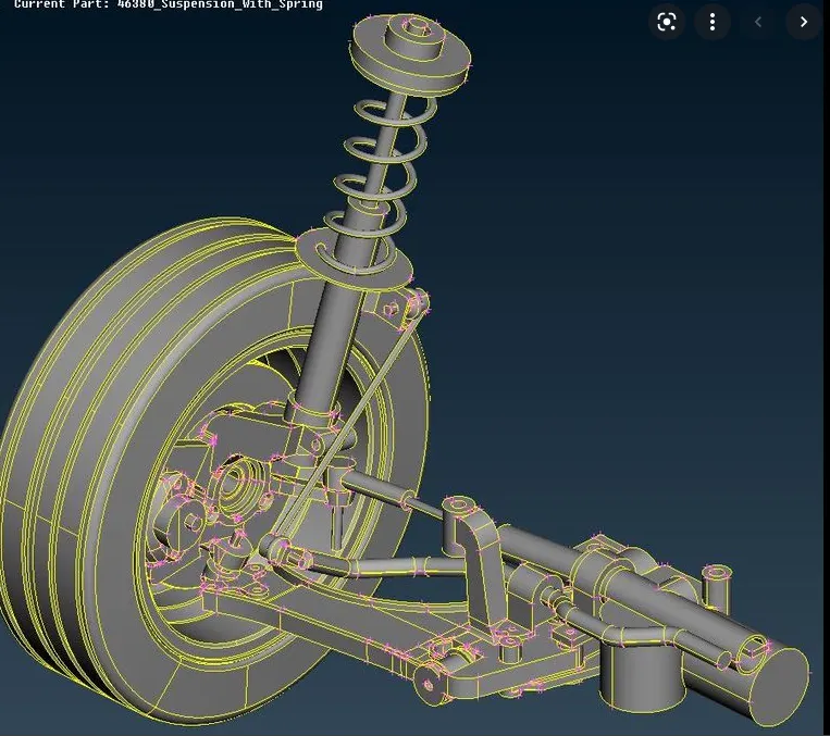
Procedure -
- There are 3 types of meshing involved in this model, we start with the 1D meshing of the spring bar elements :
Generate a middle curve using the middle curve option as shown :
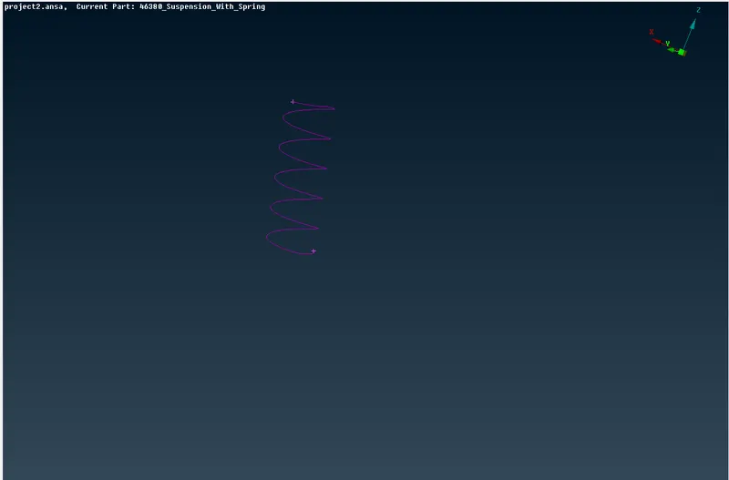
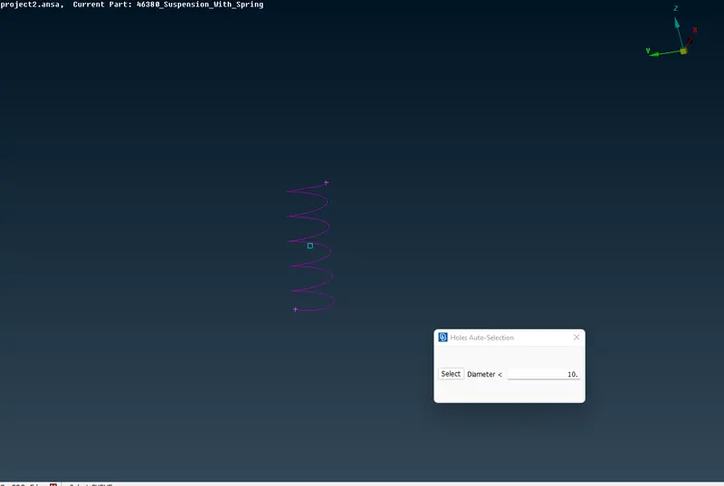
After generating the middle curve give a new point on cog using Points-COG option as shown :
Now, go to the NASTRAN deck and click on CBar, select the curves option and confirm as shown :
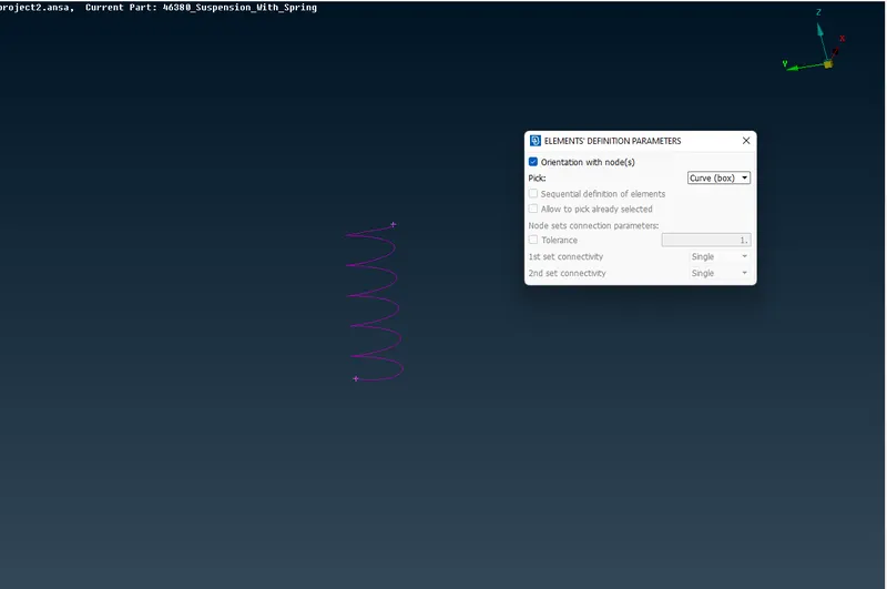
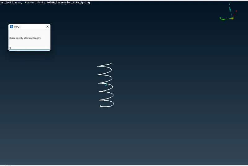
Enter target length as 3mm and radius as 5, we now get the cbar element as shown :
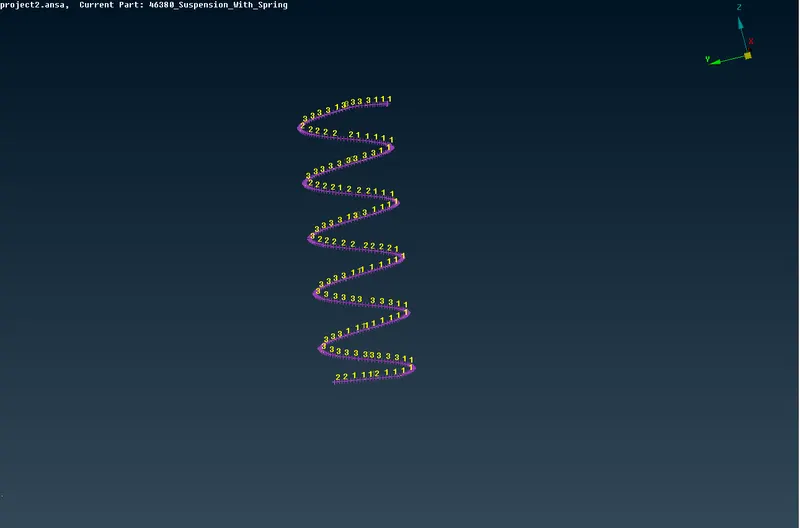
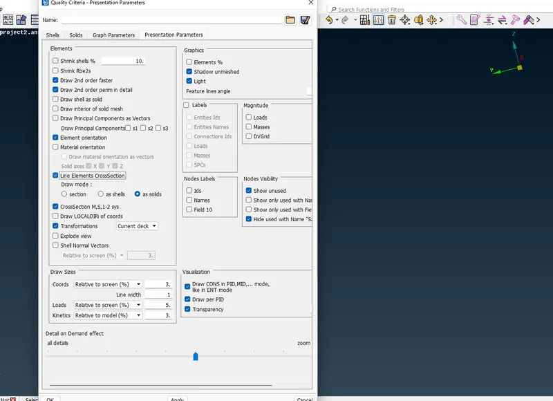
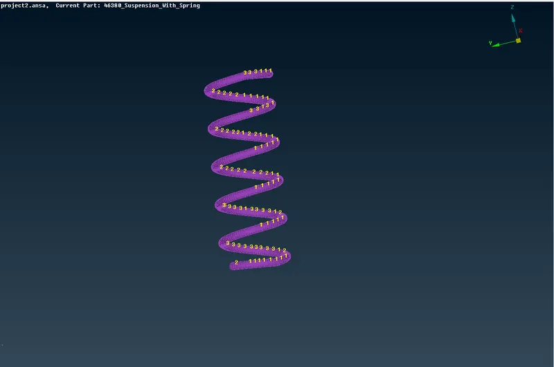
To see the 1d element as solid enable the same option in presentation parameters :
- 2D meshing is done on components whose thickness is found to be less than 5 mm:
Extract the mid surface by manual offset method and assign appropriate PID's to the mid surface :
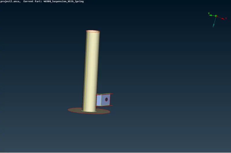
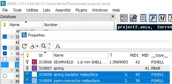
Enter the quality criteria given as shown :
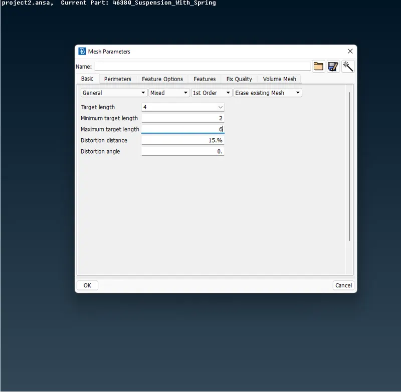
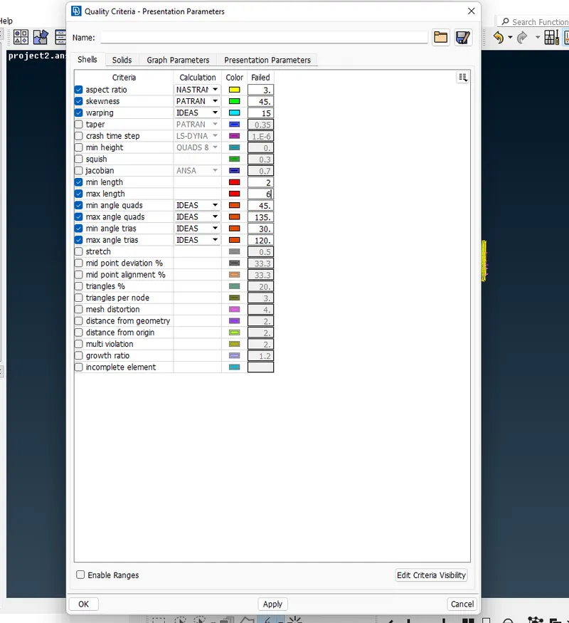
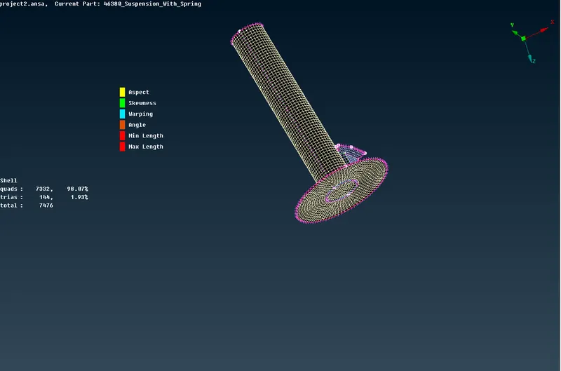
Generate the mesh using the best generate method, reconstruct, and get rid of the off elements. The final mesh is as shown :
- 3D meshing is done on components where there is no uniform thickness :
Thus no mid surfacing of such components is required, Surface meshing is done using the ortho tria & tria elements.
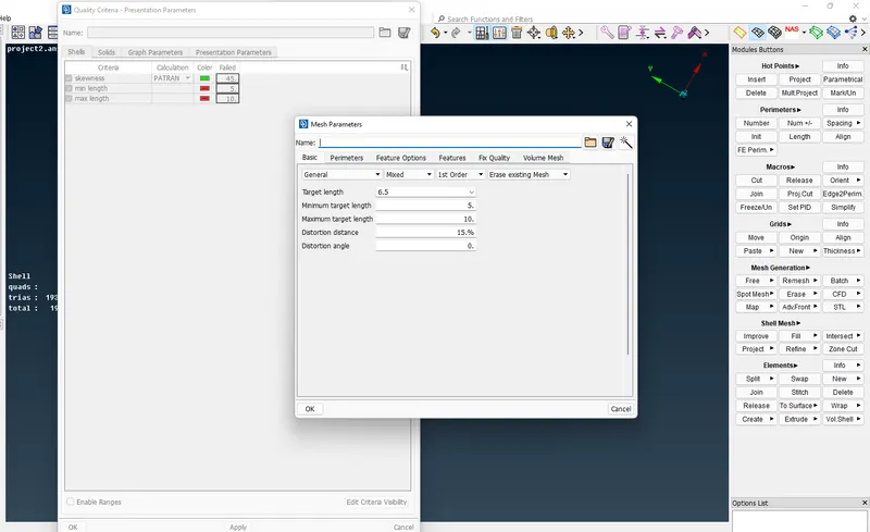
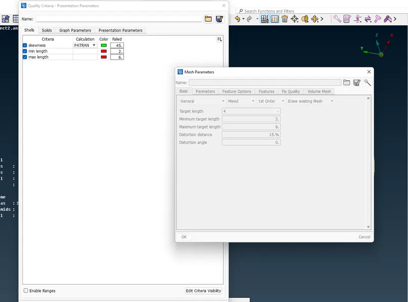
The mesh parameters and quality criteria are enabled as shown :
For Tyre and Rim :
For other non-uniform thickness parts :
We mesh the plane surfaces using tria and the curved surfaces using ortho tria as shown :
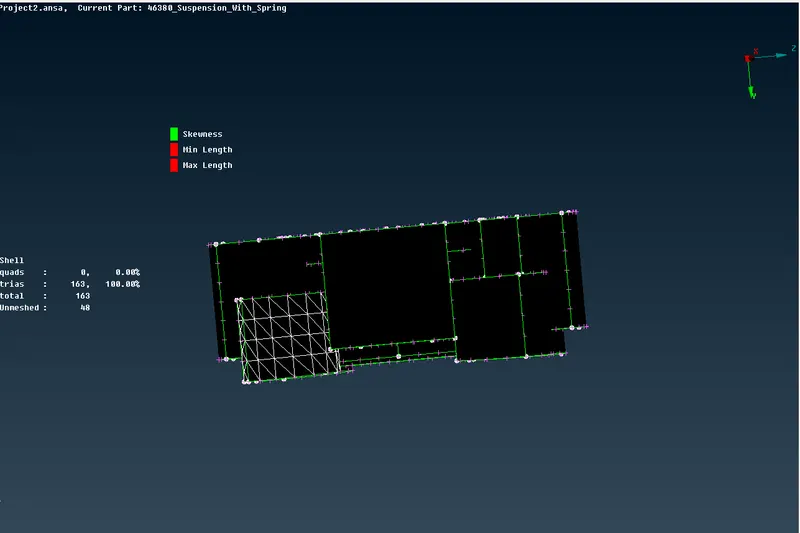
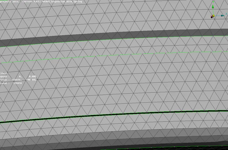
The off elements are cleared using the swap, split, paste, and move commands. The final meshes are shown below :
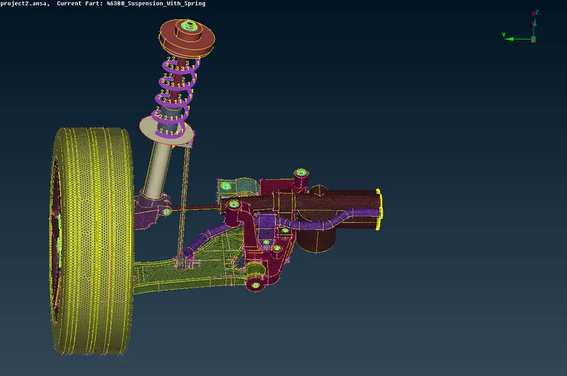
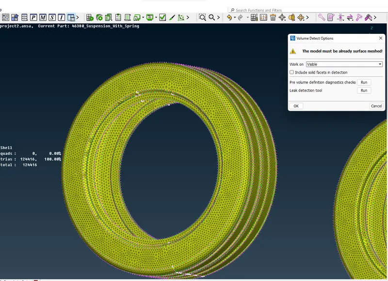
After Surface Meshing we define the volume in the 3d meshing module manually as shown :
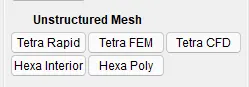
We use the Tetra Fem method for meshing the volume as it is more accurate and follows certain rules for meshing :
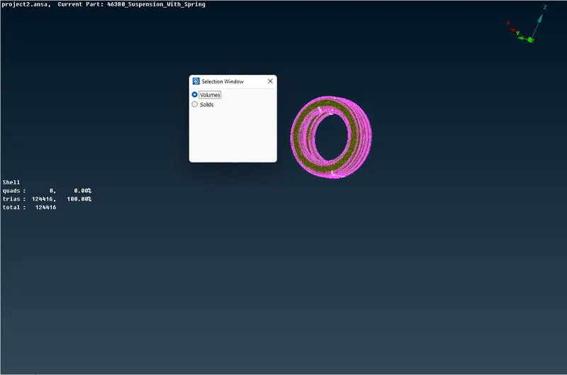
We clear the off elements, the final meshes are as shown below :
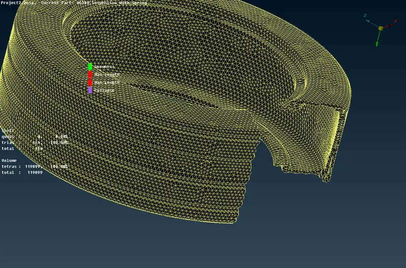
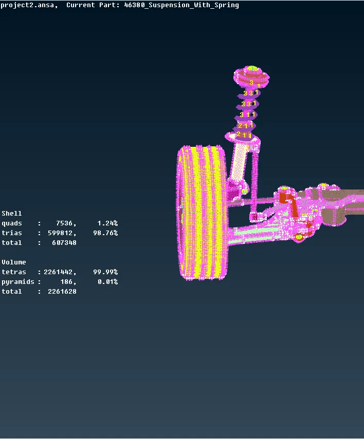
Connections :
Rbe2 Connections - these connections are given when we want to define rigid connections.
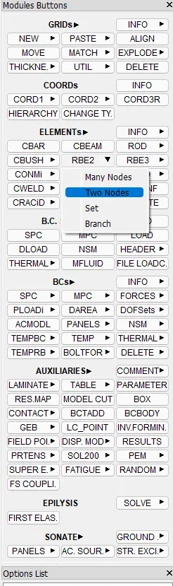
Go to the NASTRAN deck and chose Rbe2-Multi Nodes as shown :
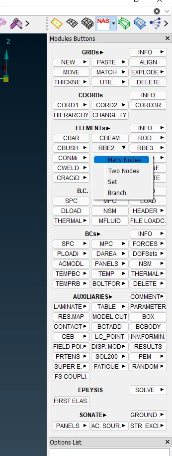
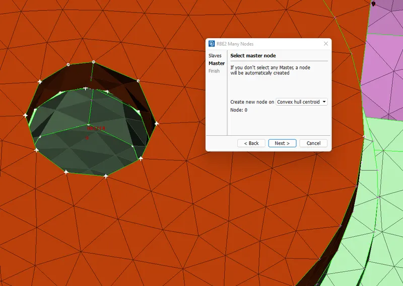
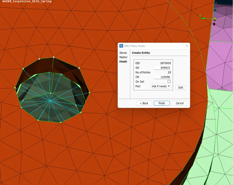
We choose Rbe2-2nodes when we want to define a bolt-stem connection as shown :
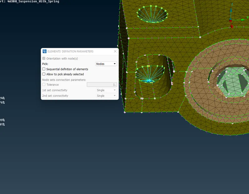
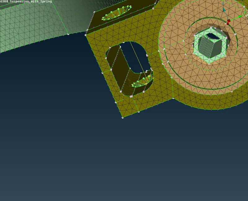
The necessary Rbe2 connections are successfully deployed as shown :
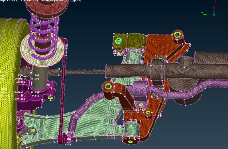
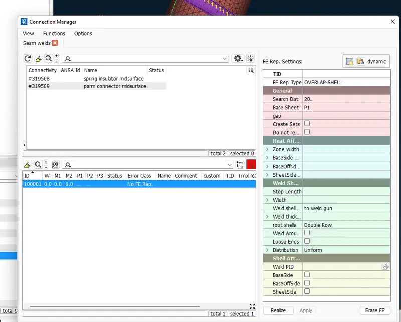
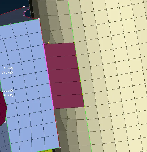
Seam Weld Connection - given to join 2 parts with one having a larger free edge.
Create a curve line using the Feat2Curve option as shown :
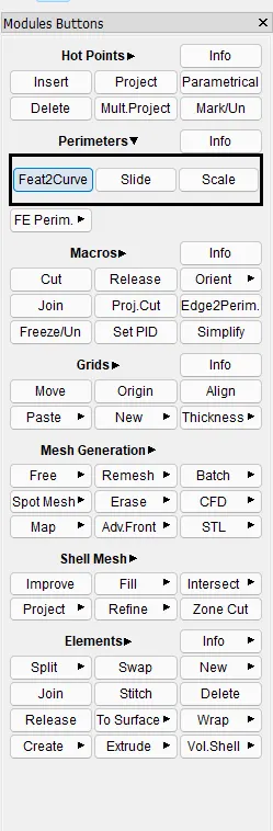
Now make the line, a seam weld line using the curves option as shown :
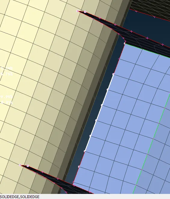
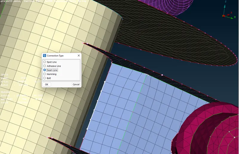
Select the seam weld line, open the connections manager and give the connection details as shown:
Symmetry :
Using the transform copy option select the entity to be copied and mirror it wrt the default symmetry plane as shown :
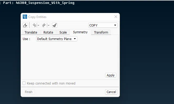
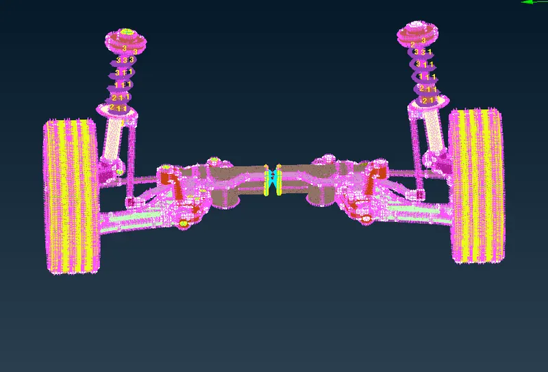
The model is copied as it is and the necessary connections have been deployed.
Learning Outcomes :
Learned different types of meshing and their respective procedures.
Different types of connections and how to give connections in a model.
The symmetry of a model
Conclusion :
The given model was cleared for geometrical errors, all the components were meshed using suitable methods, connections were made accordingly, pre-processing was carried out successfully.