Project-2-Meshing of Door Inner Panel Challenge
Project-2-Meshing of Door Inner Panel Challenge
1. Aim
- To Generate a mesh on a given 'Door Inner Panel' model after a proper geometry cleanup and mid-surface generation using Hypermesh.
- Ensure the generated mesh obeys the mentioned quality criteria and the corresponding thickness of each surface assigned to the mesh.
Objective
- Import and perform a geometry cleanup on the given model using Hypermesh.
- Assign thickness and generate a Proper mid-surface with the proper technique.
- Mesh the generated mid-surface and reconstruct the mesh to satisfy the following quality criteria.
- Model Checks
Quality Criteria
| Sl No: | Quality Criteria | Value |
| 1 | Target Element Length | 4 |
| 2 | Aspect Ratio | 5 |
| 3 | Skewness | 45 |
| 4 | Warping | 15 |
| 5 | Taper | 0.5 |
| 6 | Min. Length | 2 |
| 7 | Max. Length | 6 |
| 8 | Min. Angle Quad | 45 |
| 9 | Max. Angle Quad | 135 |
| 10 | Min. Angle Tria | 20 |
| 11 | Max. Angle Tria | 120 |
| 12 | Tria % | 10 |
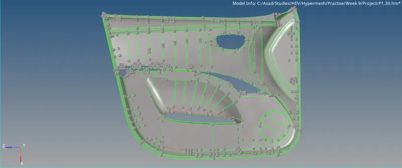
Fig 01: Isometric View Of Model.
3. Procedure
Step 1: Importing the File
First We have to import the file to hyper mesh.
- File >> Import >> Geometry >> Browse the file location >> Select The File >> Import.
Step 2: Geometric Cleanup and Extracting Midsurface.
By inspecting the model, the geometry is complex and has many surfaces, faces and features that should be covered on the mesh. To simplify this model, the geometry is divided into 5 parts using any of the 'Trim' tools and organised into different components. Also, there are some surfaces, that should be avoided during the mesh. those surfaces should be organised and hidden from the geometry.
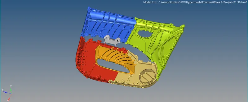
Fig 02: Diving into Small Parts
Because of complexity, The auto cleanup will not give any proper cleaning. So we have to go for manual cleanup. We can clean the geometry manually using tools provided in the quick edit panel or surface edit. The geometry is now cleaned after performing proper operations like Toggle, Washer Splits, Filling and Deleting Surfaces, and other functions. Also, Defeature the feature areas have a radius of 0.1 - 2.0 units.
The model has varying thicknesses, hence auto mid-surface is not efficient for the extraction of the mid-surface. So, we have to rely on the manual methods. By the application of Offset, Extend, Trim, Delete, Ruled, Line Extend, etc. we can generate the mid-surface of those divided parts individually. There are some areas in which we cannot extract the mid-surface (Causes disturbance to the generated mid-surface), in those places, the meshing has to be done without the help of the mid-surface.
It is a 2D meshing, which means that the maximum thickness value will be 6 units. There are some portions that have more than of thickness of 6 units. Those areas are divided into 6mm thicknesses and captured the area.
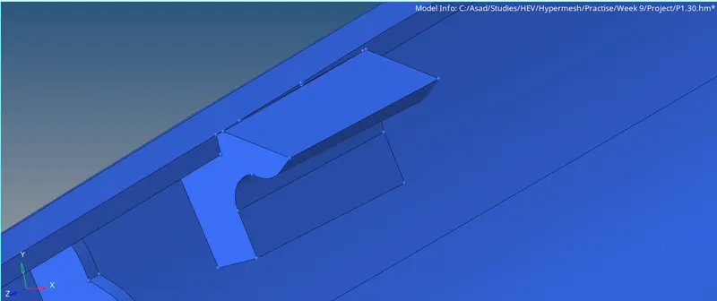
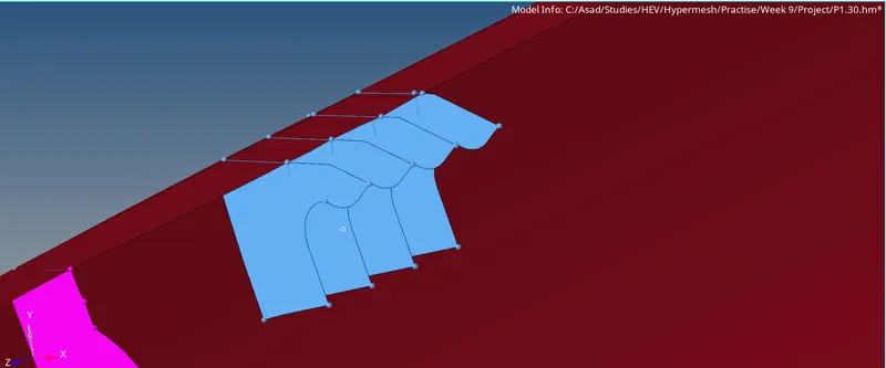
Fig 03: Mid-Surfaces of Areas Which Has More Than 6mm Thickness
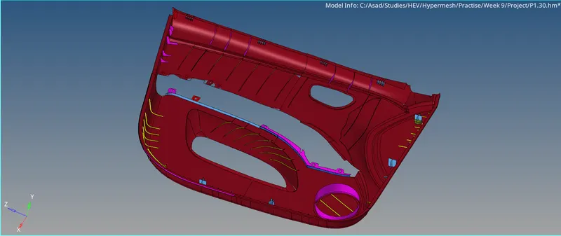
Fig 04: Extracted Mid Surface
Step 3: Property, Material, Measuring Parameters and Quality Criteria
This is a plastic model, which means that there are components with different thicknesses. So organise those components separately and assign properties based on thickness (Average Thickness). Create the property and the material for the mid-surface based on thickness and add to the mid-surface component. Then we have to assign the measuring parameters and quality criteria for the mesh.
There are 7 assemblies, 30 components, 1 material and 8 properties with different thicknesses.
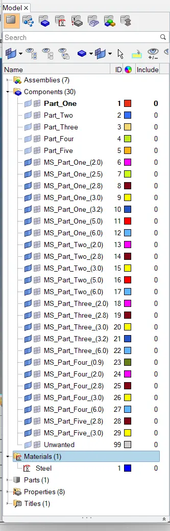
Fig 05: Assemblies, Properties and Material
For adding quality criteria,
- Preferences >> Criteria File Setting >> Input the Mentioned Quality Crieria >> Ok
For Measurement Parameters,
- Preferences >> Parameters File Setting >> Input the Target Element Length >> Ok
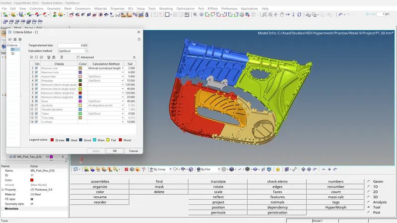
Fig 06: Quality Criteria
Step 4: Meshing the Surface
The meshing is carried out on the surface by surface. Also, adjusting the number of nodes for good mesh flow.
- 2D >> Automesh >> Select Surface >> Ok.
The mesh flow should be improved especially in feature areas. For that, we can use these functions,
- 2D >> Rebuilt >> Select the mesh elements which to be reconstructed.
- 2D >> Edit element >> Create/Combine/Split
There are several areas in which the meshing is done without the help of the mid-surface. we can use either 'Create' or 'Ruled' to create the elements. Using the 'Replace' option we can stitch other nodes of adjusting elements and achieve the equivalence. Use the 'Align' option to align the node in a straight line.
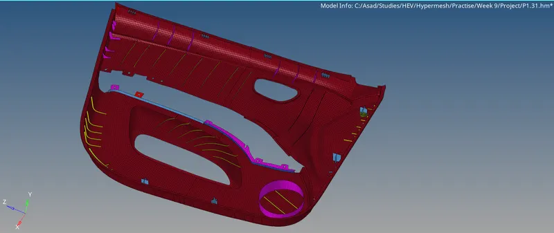
Fig 07: Generated Mesh
After correcting the mesh flow, the element quality should be checked.
- 2D >> Quality Index >> Cleanup Tools
Using the following tools, Place nodes/Smooth/Modify holes and washers/Split and Collapse Edge/Swap edge/Drag tria element/node optimise/element optimise/split quad element/combine tria element, we can simply modify elements to obey element criteria.
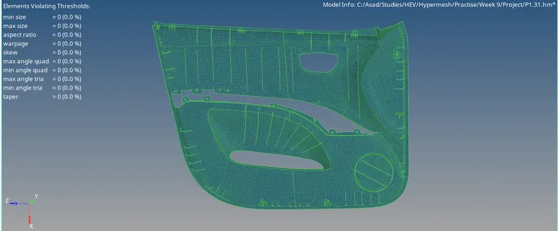
Fig 08: Quality Index
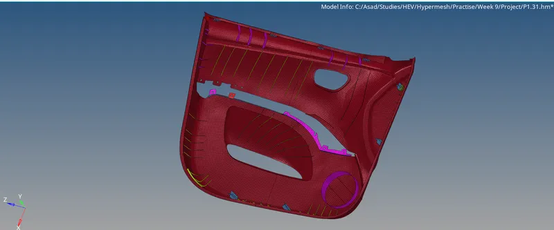
Fig 08: Final Mesh
Step 5: Model Checks
Check For Free Edges And Equivalence
- Tools >> Edges >> Select Elements >> Adjust The Tolerance Value (~0.5) >> Find edges. >> Delete Edges >> Preview Equivalence >> Equivalence.
If the equivalence is not achieved, we can use the 'Replace' option to stitch the adjacent nodes.
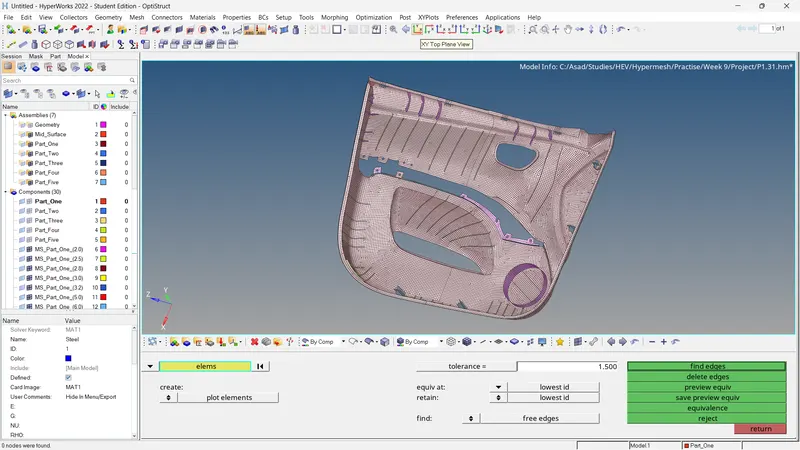
Fig 09: Checking of Equivalence
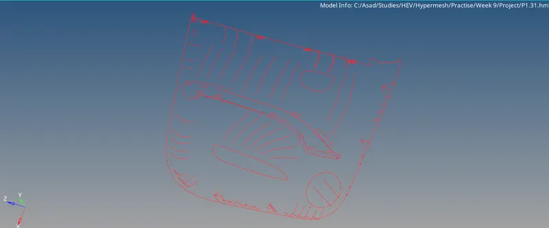
Fig 10: Checking of Free Edges
Check For Connectivity and Duplicates
For Connectivity
- Tools >> Check Elements >> 2D >> Connectivity.
For finding duplicates,
- Tools >> Check Elements >> 2D >> Duplicates.
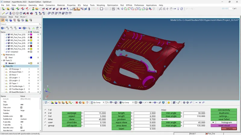
Fig 11: Connectivity and Duplicates
Check For Normals
- Tools >> Normal >> Elements >> Color Display >> Display.
If any of the vectors have opposite directions, it can be corrected by Using the 'Adjust' option.
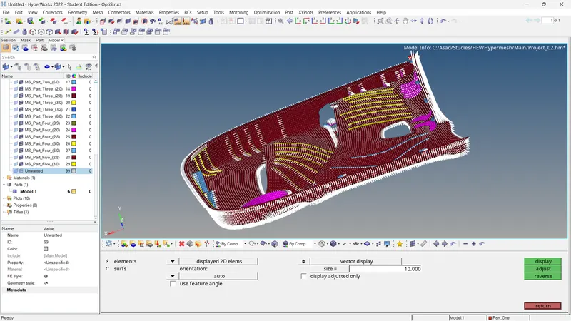
Fig 12: Check For Normals
Check For Penetration and Dependency
For penetration/intersections checks,
- Tools >> Penetration >> Select Elements >> Check
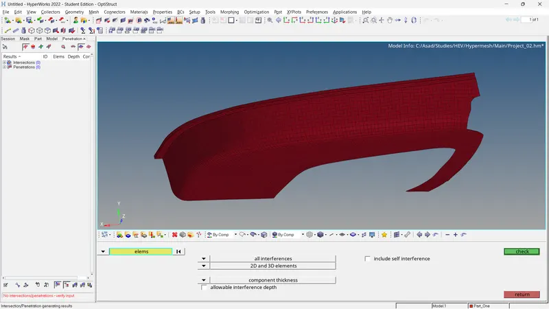
Fig 13: Check For Penetration
For dependency checking,
- Tools >> Dependency >> Select Elements >> Dependency
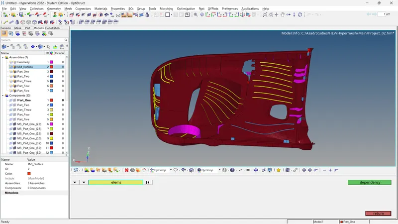
Fig 14: Check For Dependency
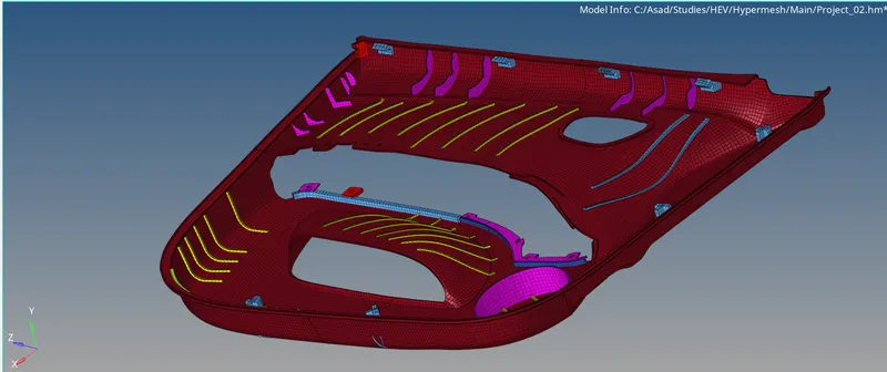
Fig 15: Final Result
4. Conclusion
- The mid surface of the given model is generated, assigned properties based on thicknesses, and materials and adds quality criteria and target element lengths for every one of the components.
- The meshing and reconstruction of a generated mesh of each component are completed.
- Model checking is finished.
5. Results
- For the given Plastic model, the mid-surface is extracted and mesh generated. The generated mesh satisfies the following quality criteria and the model checks are completed.