Project 2 - Measuring distance of an object using ultrasonic sensor (HC-SR04)
Aim: To implement a code for measuring the distance of an object using an ultrasonic distance sensor (HC-SR04).
Theory:
An ultrasonic sensor is an instrument that measures the distance to an object using ultrasonic sound waves. An ultrasonic sensor uses a transducer to send and receive ultrasonic pulses that relay back information about an object's proximity. Ultrasonic waves travel faster than the speed of audible sound (i.e. the sound that humans can hear). Ultrasonic sensors have two main components: the transmitter (which emits the sound using piezoelectric crystals) and the receiver (which encounters the sound after it has traveled to and from the target).
HC-SR04 is an ultrasonic ranging sensor that provides a 2 cm to 400 cm non-contact measurement function. The ranging accuracy can reach 3mm and the effectual angle is < 15°. It can be powered by a 5V power supply.
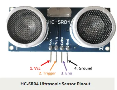
Ultrasonic Sensor Pinout Configuration:
Pin Pin Name Description
1 Vcc The Vcc pin powers the sensor, typically with +5V
2 Trigger The trigger pin is an Input pin. This pin has to be kept high for 10us to initialize measurement by sending a US wave.
3 Echo The echo pin is an Output pin. This pin goes high for a period of time which will be equal to the time taken for the US wave to return back to the sensor.
4 Ground This pin is connected to the Ground of the system.
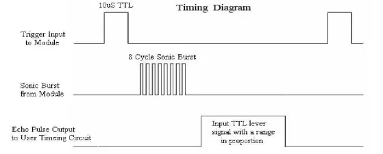
Timing Diagram:
We need to supply a short 10uS pulse to the trigger input to start the ranging, and then the module will send out an 8-cycle burst of ultrasound at 40 kHz and raise its echo. The Echo is a distance object that is pulse width and range in proportion. We can calculate the range through the time interval between sending the trigger signal and receiving the echo signal.
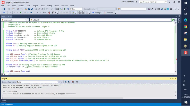
Code:
/* “Measuring distance of an object using ultrasonic distance sensor (HC-SR04)
 * project2_US.c
 * Created: 01-07-2023 01:13:19 Author : Rajni */

#define F_CPU 8000000UL			// defining CPU frequency = 8 MHz
#include <avr/io.h>				// input-output library
#include <avr/interrupt.h>		// Interrupt library
#include <util/delay.h>			// delay library
#include <stdlib.h>				// standard library

#define EN 0 // defining Enable Pin of LCD
#define RS 1// defining Register Select signal pin of LCD

#define lcdport PORTD //making PORTD as LCD port for connecting LCD

void LCD_command (char); //Function Prototype for LCD Command
void LCD_data (char); // Function Prototype for writing data on LCD
void LCD_init (void); // Function Prototype to initialize LCD
void LCD_print (char,char,char*); // Function Prototype for printing data at respective row, column position on LCD

#define TP PA0 // Defining Trigger Pin of Ultrasonic Sensor as PA0
int TimerOverflow =0; //global variable for timer overflow

void LCD_command (char cmd)
{
	lcdport = cmd;
	PORTC &=~(1<<RS); // RS = 0 for command
	PORTC |= (1<<EN); // EN = 1
	_delay_ms(1);
	PORTC &=~(1<<EN);; // EN = 0
}
void LCD_data (char data)
{
	lcdport = data;
	PORTC |= (1<<EN) |(1<<RS); // EN = 1 and RS=1 for data
	_delay_ms(1);
	PORTC &=~(1<<EN);; // EN = 0
}

void LCD_init(void)
{
	DDRC |= (1<<RS)|(1<<EN);
	DDRD = 0xff; //define output port
	LCD_command(0x38); // LCD in 8 bit mode
	_delay_ms(1);
	LCD_command(0x0C); // Display ON cursor OFF
	_delay_ms(1);
	LCD_command(0x06); //Increment Cursor
	_delay_ms(1);
	LCD_command(0x01); // Clear LCD
	_delay_ms(1);
	LCD_command(0x80); // first line/row 0th position/column
	_delay_ms(1);
}

void LCD_print(char row,char col,char *str)
{
	if((row<0 || row>2) && (col<0 || col>16)) //loop when cursor is beyond LCD position
	{
		row = 0;
		col = 0;
	}
	if (row == 1)
	{
		LCD_command(0x80+col); //first row and mentioned column
	}
	else
	{
		LCD_command(0xC0+col); //second row and mentioned column
	}

	while(*str) // for printing data on LCD
	{
		LCD_data(*str);
		++str;
	}
}

int main(void)
{
	char ch[10]; // string to print on LCD
	double count; // variable for Timer Count
	double dist; // Distance Variable
	DDRA = 0x01; // Trigger Pin as output
	PORTA = 0xff; // Activate Pull up Registers
	LCD_init();
	LCD_print(1,0,"AVR PROJECT II");
	sei(); // Enable Global Interrupt
	TIMSK = (1<<TOIE1); // Enable Timer1 Overflow Interrupt
	TCCR1A = 0; // set all bits to zero for normal mode operation

	while (1)  //10 us trigger pulse
	{
		PORTA |= (1<<TP); // PB4 for Trigger Pin
		_delay_us(10);
		PORTA &=~(1<<TP);
		TCNT1 = 0; // clear timer counter
		TCCR1B = 0x41; //capture on rising edge, No prescalar
		TIFR = 1<<ICF1; //clear input capture flag
		TIFR = 1<<TOV1; //clear Timer overflow flag

		//Calculating width of echo by input capture//

		while((TIFR & (1<<ICF1))== 0); // wait for rising edge

		TCNT1 = 0; // clear timer counter
		TCCR1B = 0x01; //capture on falling edge, No prescalar
		TIFR = 1<<ICF1; //clear input capture flag
		TIFR = 1<<TOV1; //clear Timer overflow flag
		TimerOverflow = 0; //clear Timer overflow count

		while((TIFR & (1<<ICF1))== 0); // wait for falling edge

		count = ICR1 + (65535*TimerOverflow) ; // count value wrt Timer1
		dist = count / 466.47;
		dtostrf(dist,2,2,ch); // double to string conversion

		LCD_print(2,1,"Dist=");
		LCD_print(2,6,ch);
		LCD_print(2,12,"cm");
		_delay_ms(100);
	}
	return 0;
}

ISR(TIMER1_OVF_vect)
{
	TimerOverflow++;
}
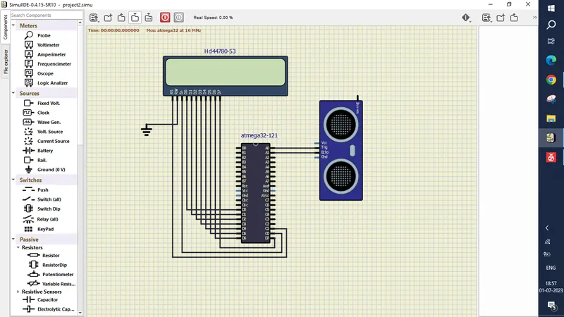
SimulIDE Circuit:
Components used:
- LCD Panel.
- Atmega32
- Ultrasonic Sensor HC-SR04
- Ground
- Connecting Wires
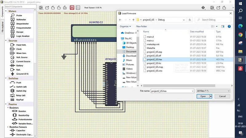
Loading Hex File:
Output:
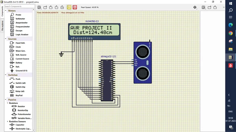
Result:
- The distance traveled by a wave to the object was calculated using Ultrasonic Distance Sensor (HC-SR04).
- The Pulse width was measured using the Input Capture Mode of Timer 1
- Studied an Ultrasonic sensor (HC-SR04), which is used to measure the distance traveled by wave to the object.