Project 1 (Mini Project on Vehicle Direction Detection
AIM OF PROJECT:
To develop a MATLAB Simulink model of Vehicle Direction Determination as per 2 requirement statements.
REQUIREMENTS:
Requirement - 1:
- Steering wheel input as yaw rate (Signal name: SteeringWheel_YawDegreeInput) is the input for this system.
- This is compared against 3 angular values, one each for the left turn, right turn & straight drive (Calibration Values: Right_Turn_AngularLimit, Left_Turn_AngularLimit, Straight_Drive_Steering_Angle) to say which specific direction the steering wheel is turning towards.
- Use switch blocks to compare & develop this requirement. Keep this requirement in a subsystem & the output of this requirement is a local signal (Signal Name: Vehicle_Turn_Status).
Requirement – 2:
- Keep this requirement as a separate subsystem. Inputs to this requirement are local signal from requirement 1 (Signal Name: Vehicle_Turn_Status) & an input signal from the camera (Signal Name: CameraInput_RoadSign), which confirms the occurrence of a road sign.
- Signal Vehicle_Turn_Status is compared against calibration values (Calibration Values: RightTurn_RoadSign, LeftTurn_RoadSign, Straight_RoadSign), if each of them is found equal, then each of the three corresponding outputs is compared against the camera input signal.
- Using a logical operator block, only one among them is finally given as the output signal (Signal Name: Vehicle_Direction_Indicator.
DESCRIPTION:
(After Model Advisor Run & Removing some Warnings)
Simulink Model Name: ‘MP_VDD.slx’
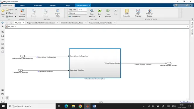
As we can see this is the base root architecture of our model. It has a subsystem named ‘VehicleDirectionDetection_Model’ with two input signals ‘SteeringWheel_YawDegreeInput’ and ‘CameraInput_RoadSign’ and an output signal ‘Vehicle_Direction_Indicator’, coming from the subsystem.
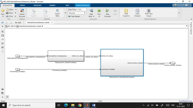
Inside subsystem ‘VehicleDirectionDetection_Model’, we have 2 subsystems named ‘Requirement1_VehicleTurnStatus’ and ‘Requirement2_VehicleDetectionIndicator’.
The subsystem ‘Requirement1_VehicleTurnStatus’ has the input signal ‘SteeringWheel_YawDegreeInput’ coming from the base model and an output signal ‘Vehicle_Turn_Status’.
Whereas the subsystem ‘Requirement2_VehicleDetectionIndicator’ has two input signals Vehicle_Turn_Status, which is the output signal of subsystem ‘Requirement1_VehicleTurnStatus’ and ‘CameraInput_RoadSign’ coming from the base model. The output signal for this subsystem is ‘Vehicle_Direction_Indicator’ which is going to the base model.
These two subsystems are designed according to our Requirement1 & Requirement2, respectively, mentioned in the project.
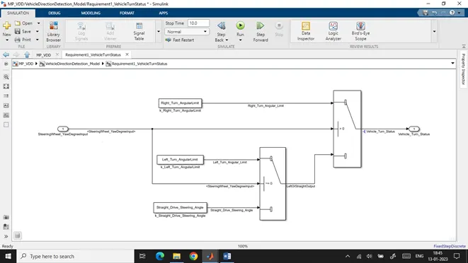
In the ‘Requirement1_VehicleTurnStatus’ subsystem, we have the input signal ‘SteeringWheel_YawDegreeInput’ coming from the base model, three calibration parameters named ‘Right_Turn_AngularLimit’, ‘Left_Turn_AngularLimit’, and ‘Straight_Drive_Steering_Angle’ and ana output signal ‘Vehicle_Turn_Status’.
The switch blocks are used for comparing the input signal, determining the turning movement of the vehicle, and setting the output accordingly with calibration parameters values.
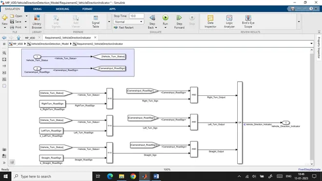
In the ‘Requirement2_VehicleDirectionIndicator’ subsystem, we have two input signals ‘Vehicle_Turn_Status’ and ‘CameraInput_RoadSign’ coming from the base model, three calibration parameters named ‘Right_Turn_RoadSign’, ‘Left_Turn_RoadSign’, and ‘Straight_ RoadSign and an output signal ‘Vehicle_Direction_Indicator.
The relational operators are used for comparing the input signal ‘Vehicle_Turn_Status’ with calibration parameters. Further, the outputs are again compared with ‘CameraInput_RoadSign’ using a logical operator to determine the output ‘Vehicle_Direction_Indicator’.
The logic used here is as per requirement 2 of the project.
REQUIREMENT 1 TAGGING:
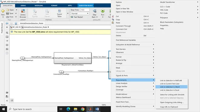
For tagging the requirements to a specific block, first, we need to select the lines in our WordPad, then right-click on the Simulink block, select ‘Requirements’, then ‘Link to Selection in Word’.
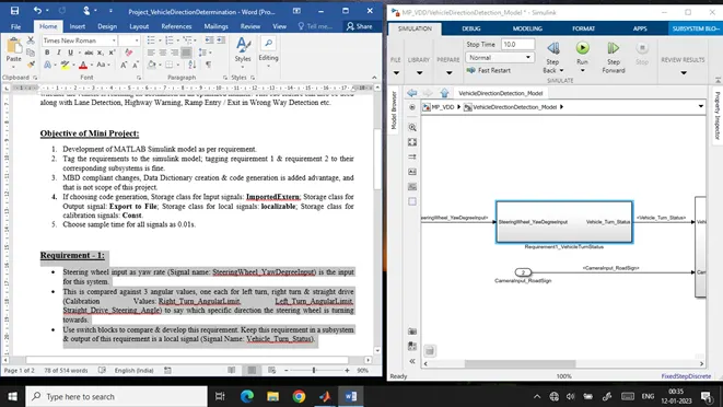
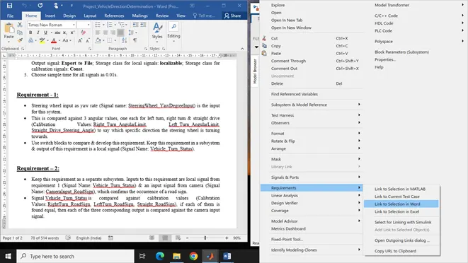
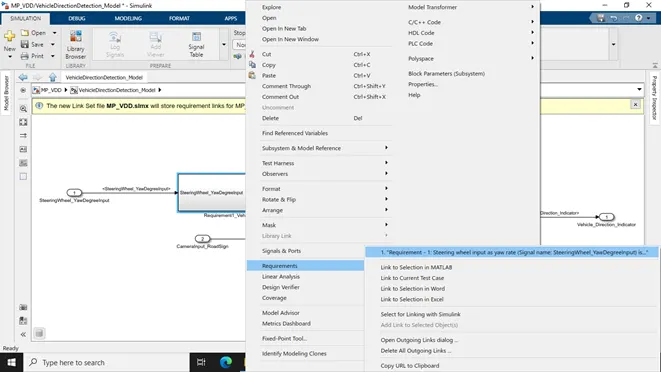
Here we see that the subsystem ‘Requirement1_VehicleTurnStatus’ containing the model of requirement 1 has been tagged.
REQUIREMENT 2 TAGGING:
Similarly, we can do requirement 2 tagging.
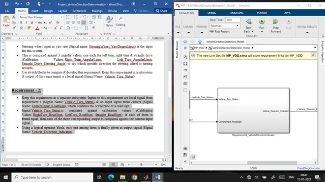
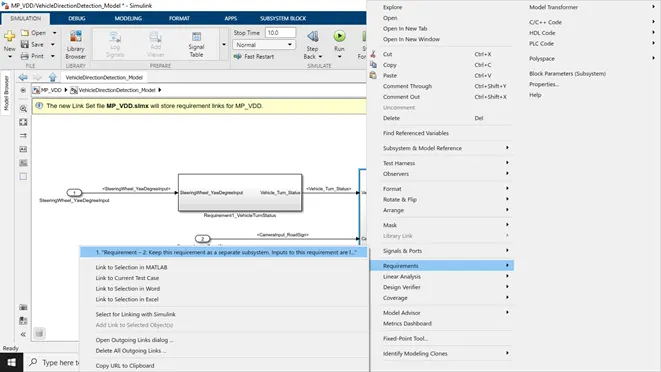
Here we see that the subsystem ‘Requirement2_VehicleDirectionIndicator’ containing the model of requirement 2 gets tagged.
SIMULINK DATA DICTIONARY:
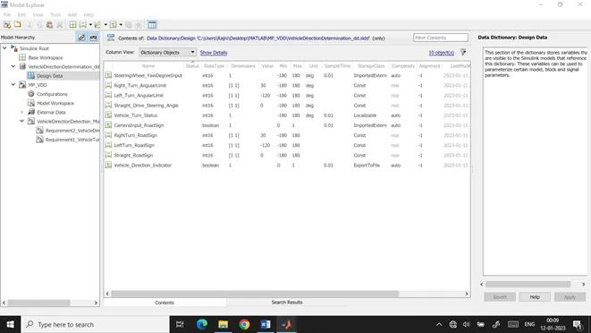
A new simulink data dictionary for this project is created named ‘VehicleDirectionDetermination_dd.sldd’ and is linked to our model ‘MP_VDD.slx’. All the signals and calibration parameters are added according to below table provided to us in requirement document.
Signals & Calibration Data List:
|
Signal / Calibration Name |
Signal Type |
Data Type |
Dimension |
Min |
Max |
Initial Value |
Units |
|
SteeringWheel_YawDegreeInput |
Input |
Int16 |
1 |
-180 |
180 |
- |
Deg |
|
CameraInput_RoadSign |
Input |
Boolean |
1 |
0 |
1 |
- |
- |
|
Vehicle_Turn_Status |
Local |
Int16 |
1 |
-180 |
180 |
- |
Deg |
|
Right_Turn_AngularLimit |
Calibration |
Int16 |
[1 1] |
-180 |
180 |
30 |
Deg |
|
Left_Turn_AngularLimit |
Calibration |
Int16 |
[1 1] |
-180 |
180 |
-120 |
Deg |
|
Straight_Drive_Steering_Angle |
Calibration |
Int16 |
[1 1] |
-180 |
180 |
0 |
Deg |
|
RightTurn_RoadSign |
Calibration |
Int16 |
[1 1] |
-180 |
180 |
30 |
|
|
LeftTurn_RoadSign |
Calibration |
Int16 |
[1 1] |
-180 |
180 |
-120 |
|
|
Straight_RoadSign |
Calibration |
Int16 |
[1 1] |
-180 |
180 |
0 |
|
|
Vehicle_Direction_Indicator |
Output |
Boolean |
1 |
0 |
1 |
- |
- |
Here as given in the project objectives:
The storage class for Input signals is ImportedExtern;
Storage class for Output signal is set as Export to File;
Storage class for local signals is given as localizable;
The storage class for calibration signals is Const.
Also, the sample time for all signals is set to 0.01s.
CONFIGURATION SETTINGS (Ctrl+E)
We need to set and adjust some configuration settings according to different guidelines.
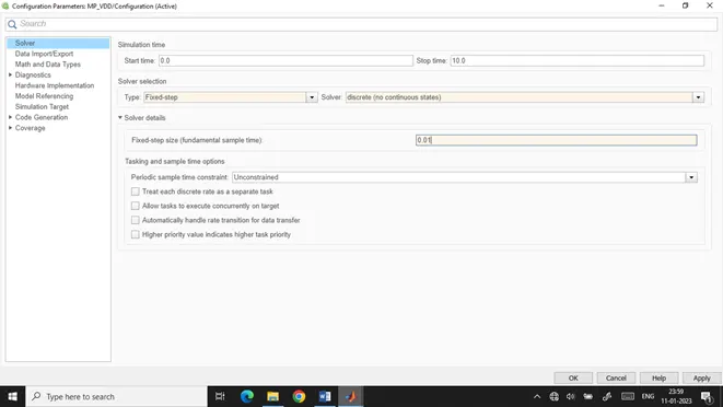
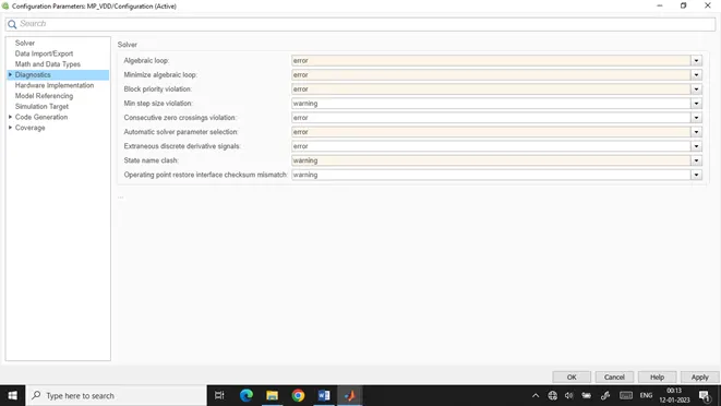
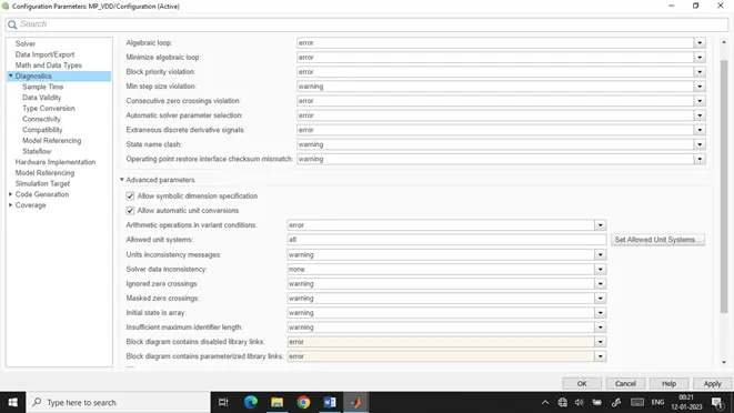
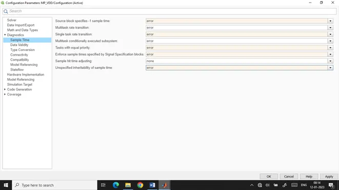
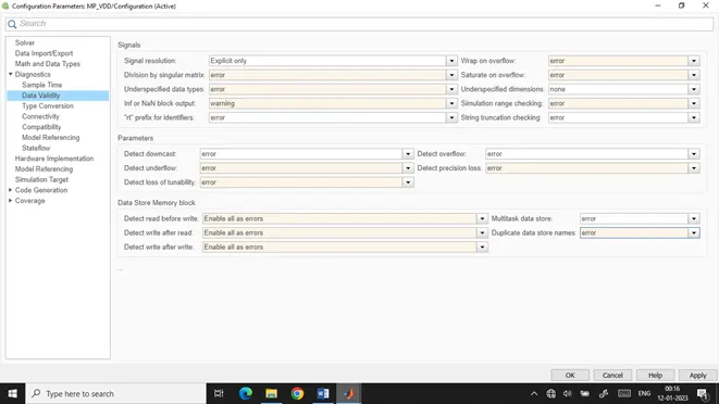
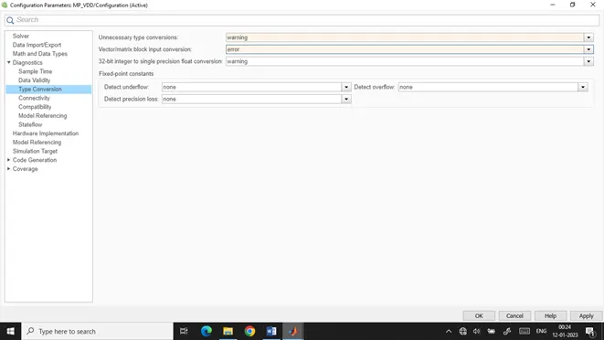
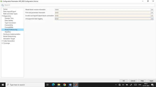
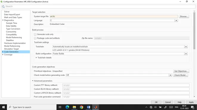
For the code generation, we need to change our target file to ‘ert.tlc’ from ‘grt.tlc’.
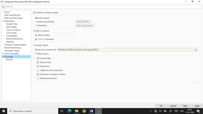
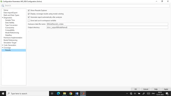
As per Coverage settings, we will check the checkbox saying ‘Enable coverage analysis’ if we are going for MIL testing.
Some of the configuration settings are also adjusted after running model advisor to remove some warnings.
MODEL ADVISOR:
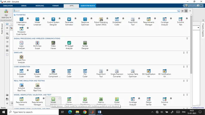
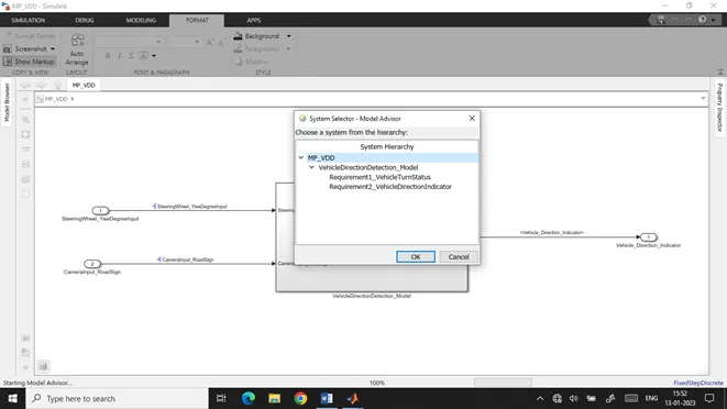
We will go to the model advisor in the APPS tab to check whether the model follows various guidelines.
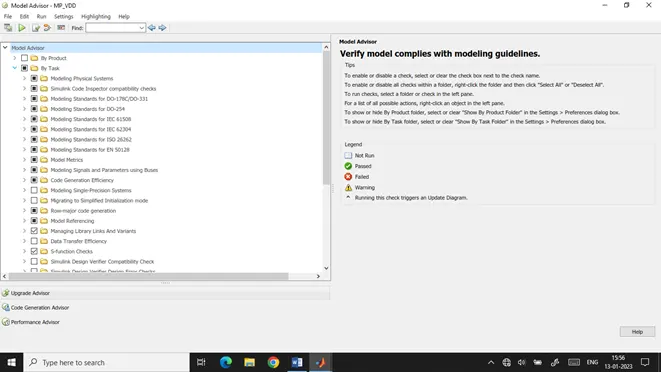
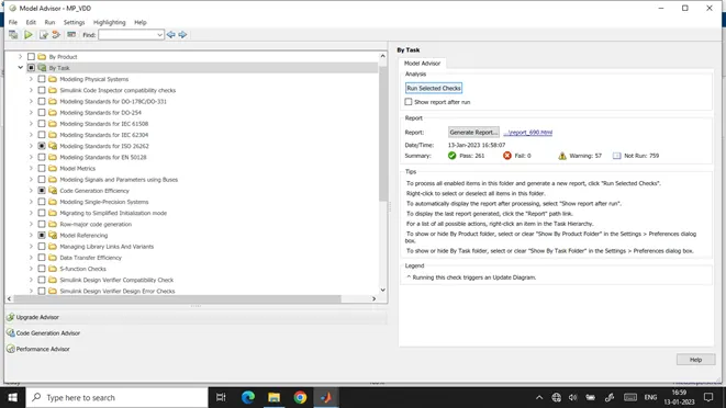
This is when the model advisor opens. By default, some task is checked. We can check or uncheck some tasks according to our model requirements.
So we have selected some of the tasks like Modelling Standards for ISO 26262, MAB Guidelines, JMAB Guidelines, MISRA Guidelines, etc. So when the following are selected for checks, we see that although there are no fails we can see some warnings. These same warnings can be looked into and can be adjusted so that warnings number can be reduced.
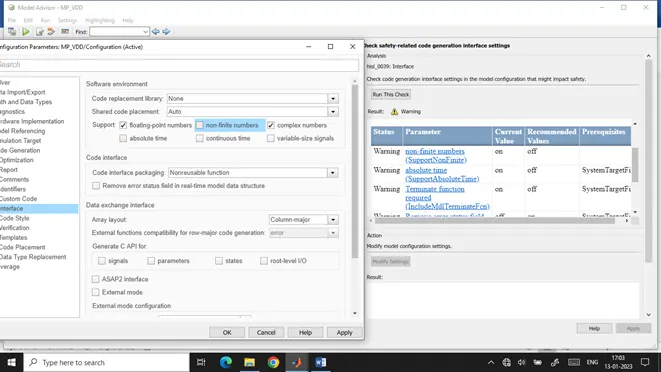
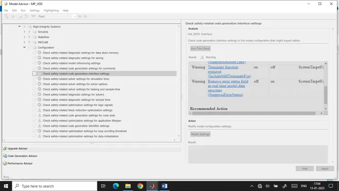
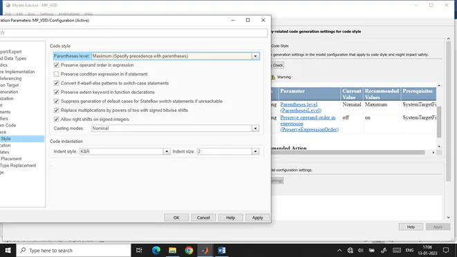
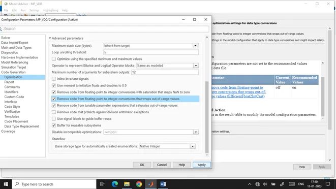
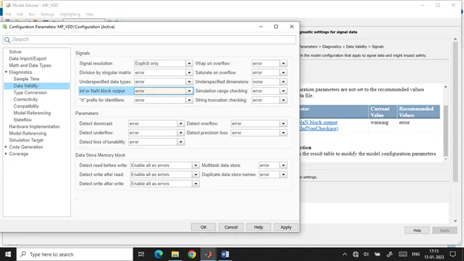
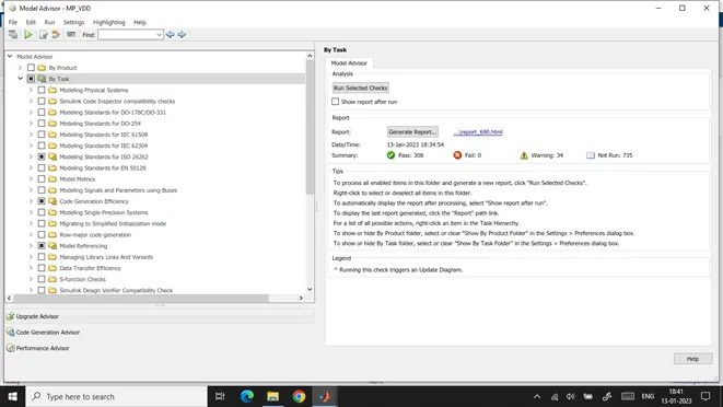
After making proper warning adjustments, again when we run the task, we see that the warnings count decreases.
GENERATE REPORT:
To generate a model advisor report, click on Generate Report option.
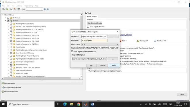
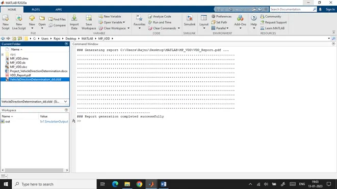
A new dialog box opens where we can name and select the format of our report to be generated.
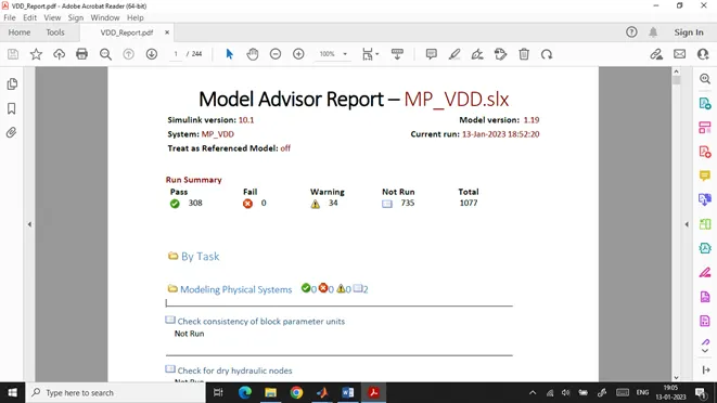
The report generated can be seen above.
BUILDING & CODE GENERATION:
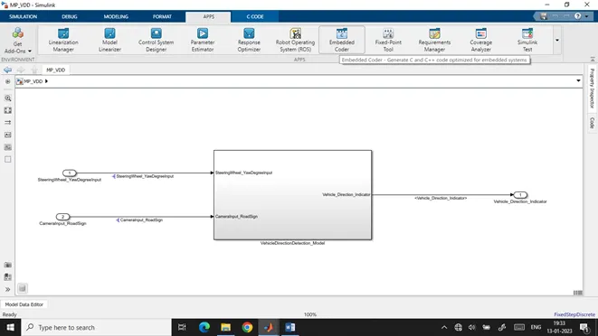
To build and generate code for the project. For the same, we will first select Embedded Coder in the APPS tab.
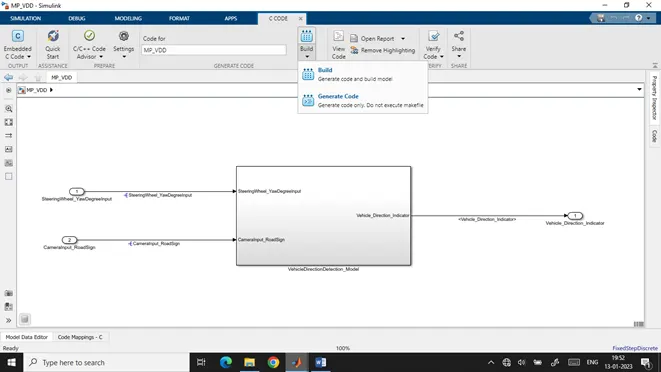
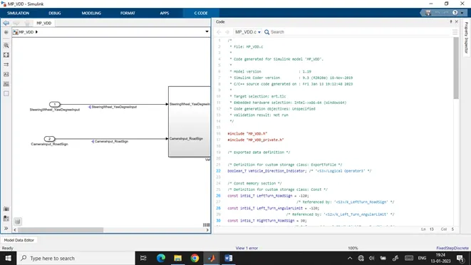
In the C CODE tab, select Build to build the model, and after that Generate Code.
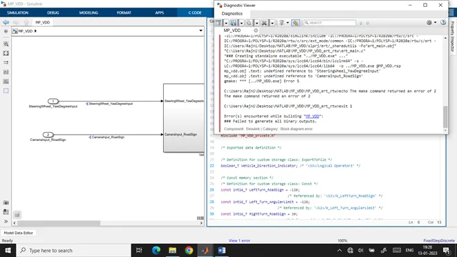
An error will pop up which says ‘Failed to Generate all binary outputs’ can be ignored as we know that the required C file takes some time to generate.
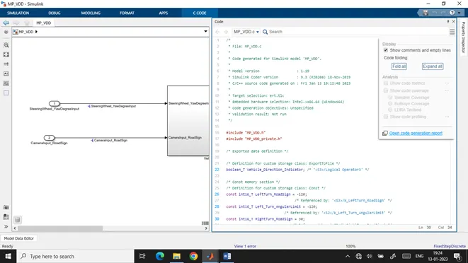
The .c file can be seen here in the above screenshot.
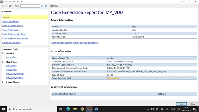
Code Generation Report for our model ‘MP_VDD.slx’