Project 2 - Measuring distance of an object using ultrasonic sensor (HC-SR04)
QUESTION:
Measuring distance of an object using ultrasonic sensor (HC-SR04)
Overview of the Project:
In this project, the implementation of code for “Measuring distance of an object using ultrasonic distance sensor (HC-SR04)
Goals:
- Measuring the distance of an object using Ultrasonic Distance Sensor (HC-SR04)
- Usage of Input Capture Mode
Key Highlights of the Project:
- Measuring the distance travelled by the wave to the object and gets bounced back from the object to sensor.
- Measuring Pulse width using Input Capture Mode
Deliverables of this project:
- The distance travelled by a wave to the object for which we want to measure the distance using Ultrasonic Distance Sensor (HC-SR04).
- Measuring Pulse width using Input Capture Mode of Timer 1
Expected Outcomes:
The students will get the Knowledge on Ultrasonic sensor (HC-SR04) to measure the distance travelled by wave to the object, the hardware connection of Atmega328p and HC-SR04 and how to use input capture mode of Timer1
SOLUTION:
---> HC-SR04 ULTRASONIC SENSOR:
- HC-SR04 is an ultrasonic distance sensor that uses ultrasound to measure the distance of an object with a range of 2cms to 400cms(4 meters).
- It stands out for its small size, good precision, and low power consumption. Light has not effect on the measurements.
- the sensor has 4 pins. 2 pins, Vcc and Gnd, are for powering up the sensor and the other 2 pins, Trig and Echo, are to send and receive the ultrasonic pulses and measure the time taken to reach and get back to the sensor to calculate the distance of an object.
- The sensor sends an ultrasonic sound wave through the trigger or trigger, bounces off the object and the receiver or echo detects the wave. By measuring the time taken for the wave from emission till it gets back we can know the distance.
WORKING PRINCIPLE:
- This sensor has 2 transducers: one is an emitter, and the other one is a receiver.
- To start measuring, the emitter emits 8 ultrasound pulses (40KHz) after receiving the HIGH command on the TRIG pin.
- The emitted sound waves travel in the air and bounce back when they hit an object, and the receiver detects the bounced-back sound waves.
- When a pulse of 10µsec or more is given to the Trig pin, 8 pulses of 40 kHz are generated. After this, the Echo pin is made high by the control circuit in the module.
- The ECHO pin stays on High (5V) from the time when the sound wave is emitted to the time the bounced-back sound wave is detected. The microcontroller measures the time of the ECHO pulse. Thus, the distance can be calculated to the object.
FORMULA:
---> Distance = {(ECHO pulse time) * (Sound speed=0.0347cm/s)}/2
As the ECHO signal time is the time taken by the sound wave to travel from the sensor to the object and the object to the sensor, we need to divide it by 2 to get the distance between the sensor and the object.
Why are we using Input capture mode to measure the distance?
The input capture function is used in many applications such as:
- Pulse width measurement
- Period measurement
- Capturing the time of an event
Timer1 can be used as an input capture to detect and measure events happening outside the microcontroller.
Upon detection of a defined event i.e. rising edge or falling edge on ICP pin , the TCNT1(Timer / Counter register) value is loaded into the ICR1 (input capture) register and the ICF1 flag will get set.
---> CIRCUIT:
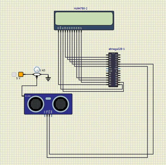
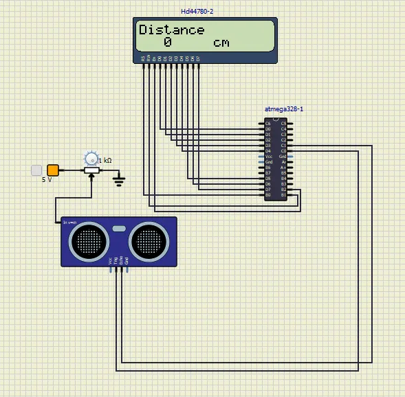
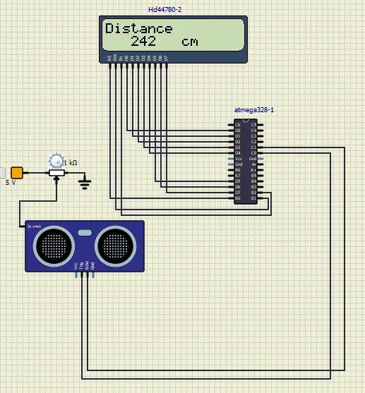
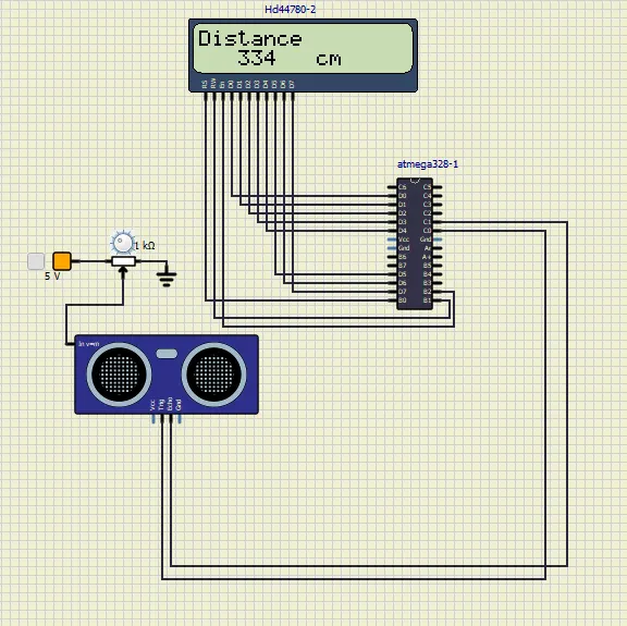
--->CODE:
#include <avr/io.h> //includes appropriate I/O definitions for the device
#define F_CPU 16000000 //tells compiler the CPU frequency to use for various delays
#include <util/delay.h> //Function where actual time values rather than a number of cycles to wait for
#include <stdlib.h> //standard library

#define  LCD_PORT PORTD //defines which PORT of ATmega will be used to interface LCD

//RS bit tells whether we are going to send an Instruction or a piece of data
#define RS_HIGH PORTB |= (1<<0); //for data
#define RS_LOW PORTB &= ~(1<<0); //for instruction

//RW bit used for read and write operation
#define RW_HIGH PORTB |= (1<<1);
#define RW_LOW PORTB &= ~(1<<1);

//EN bit enables writing to the registers if HIGH
#define EN_HIGH PORTB |= (1<<2);
#define EN_LOW PORTB &= ~(1<<2);

//global variables
#define Delay 1500000
int distance = 0;

//commands to run when the LCD RS bit is LOW
void LCD_COMMAND (unsigned char cmd)
{
	LCD_PORT = cmd;
	RS_LOW;
	RW_HIGH;
	EN_HIGH;
	_delay_ms(1);
	EN_LOW;
}

//Commands to process the data of LCD RS bit is HIGH
void LCD_DATA (unsigned char data)
{
	LCD_PORT = data;
	RW_LOW;
	RS_HIGH;
	EN_HIGH;
	_delay_ms(1);
	EN_LOW;
}

//Commands to initialize the LCD display
void LCD_INIT()
{
	RW_HIGH;
	RS_HIGH;
	EN_HIGH;
	LCD_PORT = 0xff;
	LCD_COMMAND(0x38);
	_delay_ms(5);
	LCD_COMMAND(0x02);
	_delay_ms(5);
	LCD_COMMAND(0x01);
	_delay_ms(5);
	LCD_COMMAND(0x0C);
	_delay_ms(5);
	LCD_COMMAND(0x06);
	_delay_ms(5);
	LCD_COMMAND(0x80);
	_delay_ms(5);
}

//function to set LCD Display cursor
void CURSOR_POS(char x, char y)
{
	if((x<1)|(x>2)||(y<1)|(y>16))
	{
		x = 1;
		y = 1;
	}

	if(x == 1)
	{
		LCD_COMMAND(0x7F+y); //to start from 1st line
	}
	else
	{
		LCD_COMMAND(0xBF+y); //to start from 2nd line
	}
}

void LCD_OUT(char x, char y, char* str) //to display the passed string on LCD
{
	CURSOR_POS(x, y);
	while(*str)

	{
		LCD_DATA(*str);
		str++;
	}
}

void LCD_CLEAR()//to clear the LCD display
{
	LCD_COMMAND(0x01);
	_delay_ms(2);
	LCD_COMMAND(0x80);
}

void SENSOR_Init() //setting the trigger pin as output
{
	DDRC |= (1<<0);
}

void SENSOR_Trigger() //making the trigger pin high to low after 15 microseconds
{
	PORTC |= (1<<0);
	_delay_us(15);
	PORTC &= ~(1<<0);
}

uint16_t PULSE_WIDTH() //function definition to calculate the pulse width(timer 1)
{
	uint32_t i, result; //local variables

	//waiting for some random amount of time(value of Delay)
	for(i=0; i<Delay; i++)
	{
		if(!(PINC & (1<<1))) //if less than the given time then break else continue
		continue;
		else
		break;
	}

	//checking if timer value is equal to delay given
	if(i==Delay)

		return 0;
		TCCR1A = 0x00;
		TCCR1B = (1<<CS11);
		TCNT1 = 0x00;
		for(i=0; i<Delay;i++)
		{
			if(PINC & (1<<1))
			{
				if(TCNT1 > Delay)
				break;
				else
				continue;
			}
			else
			break;
		}
		if(i==Delay)
		return 0;
		result = TCNT1;
		TCCR1B = 0x00;

		//if timer value  is greater than the given delay then result value is returned
		if(result > Delay)
		return 0;
		else
		return (result>>1);
}


//main function
int main()
{
	LCD_INIT();//LCD_INIT function call
	char numberstring[4]; //character string
	while(1)
	{
		uint16_t r;
		_delay_ms(100);
		SENSOR_Init(); //SENSOR_Init function call
		while(1)
		{
			SENSOR_Trigger(); //SENSOR_Trigger function call
			r = PULSE_WIDTH(); //storing the result value of function call in variable r
			if(r==0)//if no value is returned print error
			{
				CURSOR_POS(1,1);
				LCD_OUT(1,1,"ERROR!");
			}
			else //if value is returned calculate the distance and print
			{
				distance = (r*0.034/2.0);
				LCD_OUT(1,0,"Distance");
				itoa(distance, numberstring, 10); //converts integer into string
				LCD_OUT(2,4,numberstring);
				LCD_OUT(2,10,"cm");
				_delay_ms(30);
			}
		}
	}
}
---> SNAPSHOTS: