Project 2 - Lane National Highway Roadway Design in Civil 3D
1. Creation of Surface
Surface creation is one of the most essential aspects for road design, and Civil 3D offers several methods to create surfaces. Here are two methods by which we can create surface-
- Creation of surface by using LAND XML file -
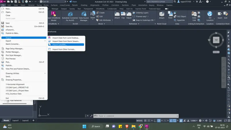
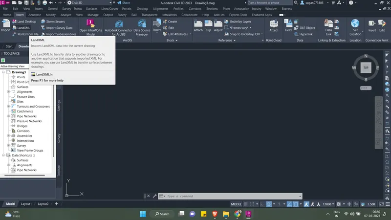
1. One can import the LAND XML file in two ways, either by going to Files --> then import --> Import LAND XML, or by going to Insert tab in ribbon --> Click on Import LAND XML. You can also go to Insert and then import LAND XML file.
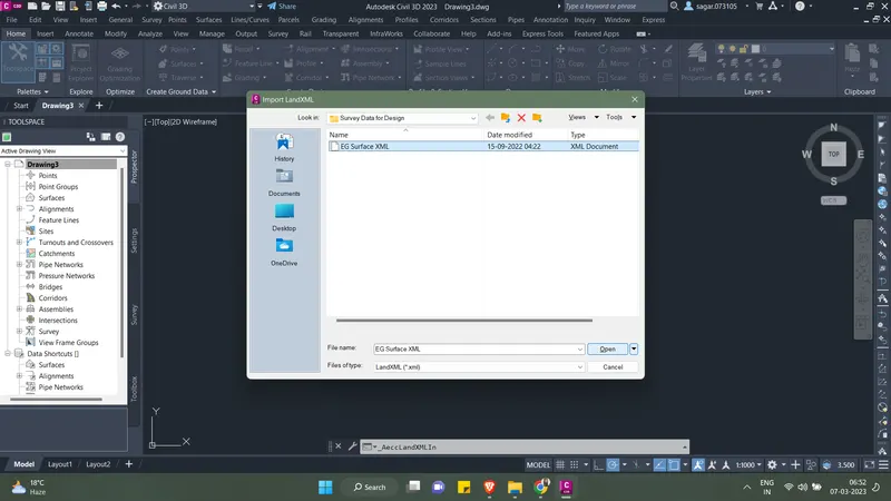
2. Select the desired XML file from the menu that appears.
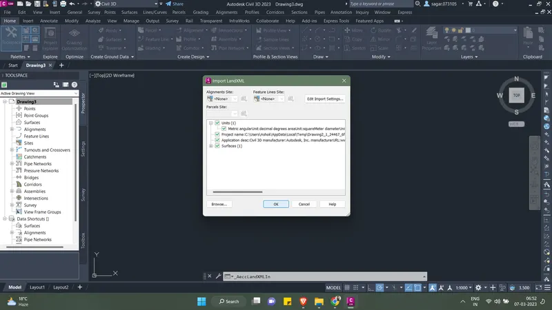
3. Keep all the options selected from the pop-up menu that appears after selecting the file. Click OK.
4. Once you click Ok, the Surface is created. You can check it in the prospector tab in Tool Space.
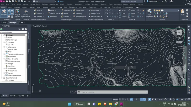
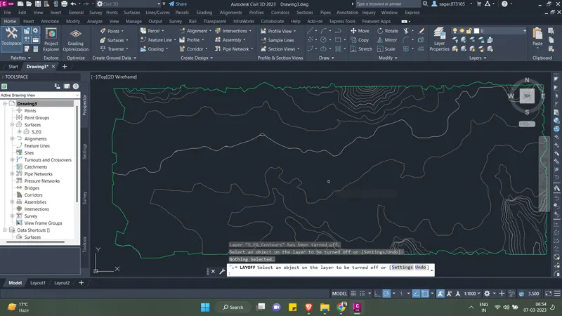
5. You can further type layoff command and turn off the contour surface layer by clicking any contour lines.
- Creation of surface by using Contour Data -
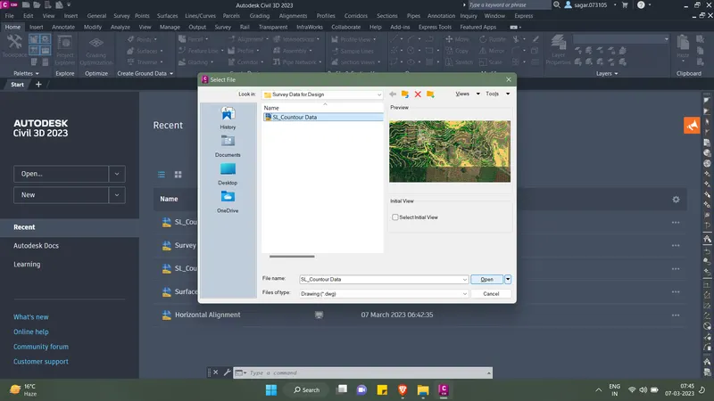
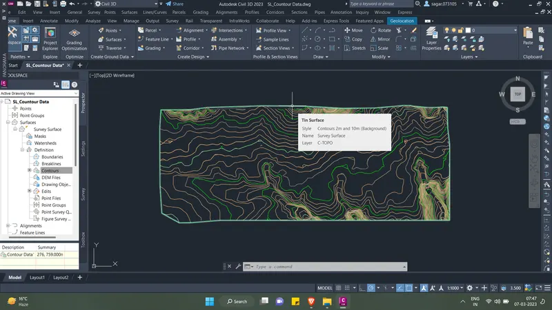
1. Go to File and click Open. Select the desired contour data file from the pop-up menu that appears and click OK. The contour data will be displayed.
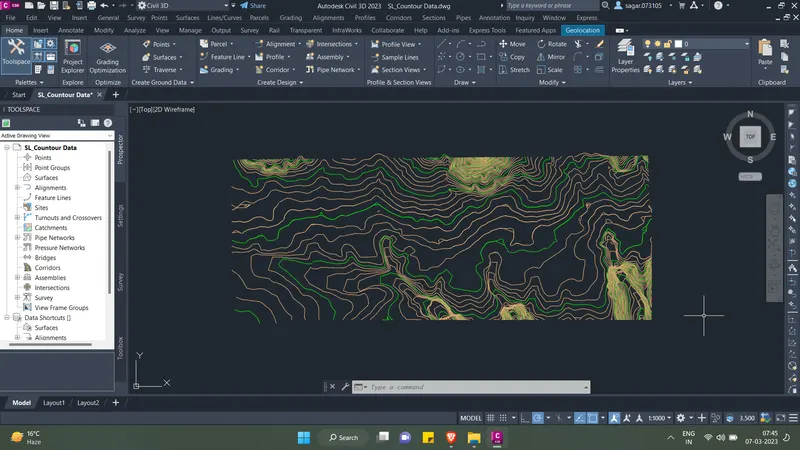
2. Now, in the Tool space, under prospector tab, right click on Surfaces option and create new surface.
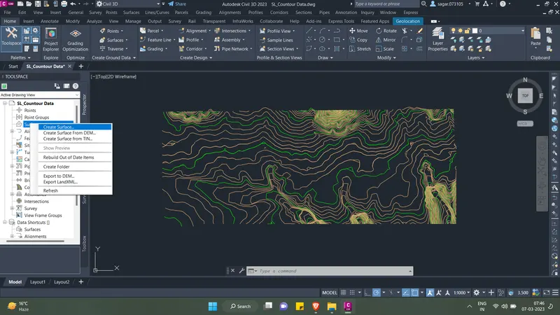
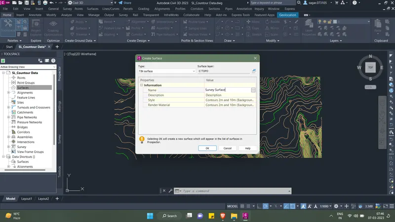
3.Once the new surface is created, then in the prospector tab under surfaces, go to the newly created surface, then click on definition, under that you can see contour option, right click on that and click add.
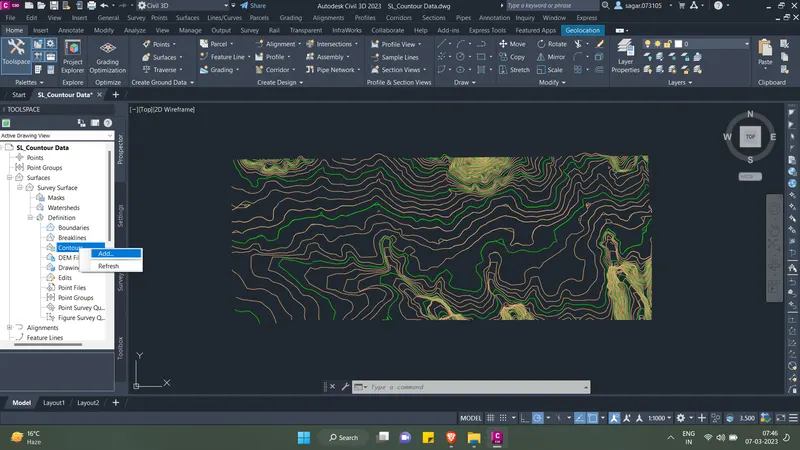
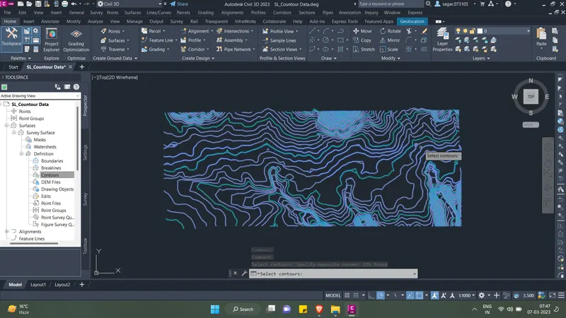
4. Add description in the pop-up menu and click OK. Now select all the contour lines on the screen and click Enter. You can see that the surface is created.
2. Alignment and Profile Design
- Alignment Design in Civil 3D
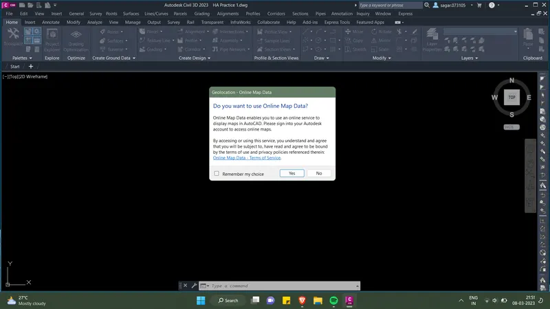
1. Now after the creation of surface, you need to add the geo location of the surface in civil 3d. You can use the template in which the geolocation is already added. If your drawing template does not contain the geolocation then in that case you can add the geolocation by adding the coordinate system code which is provided by the surveyor. If the template contains the geolocation then the following message appears on the screen, Click Yes.
2. If the above message doesn't appears the to enter the code, go to settings option in the Tool space. Then right click on your drawing and go to edit drawing settings.
3. In drawing settings, under units and zone, enter the coordinate system code provided by the surveyor. For this project the code is UTM84-43N.
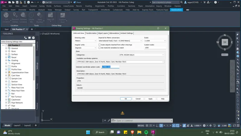
4. Once you enter the code, all the other required parameters will be set. Then Click OK. After following this process the geolocation option will be visible in the ribbon.
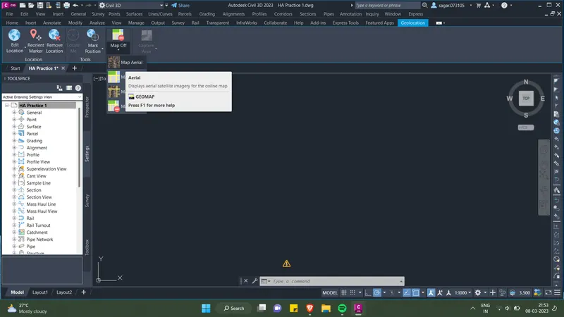
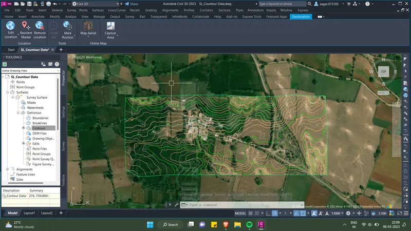
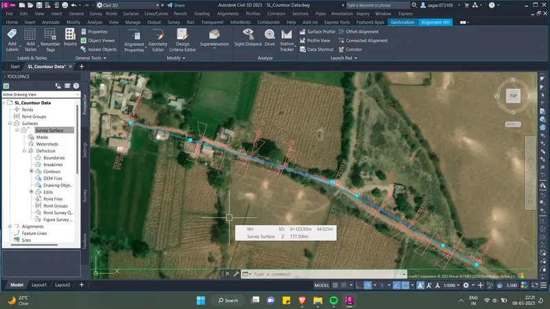
5. Then go to geolocation and under online map select aerial map. After selecting aerial map the screen will look something like this.
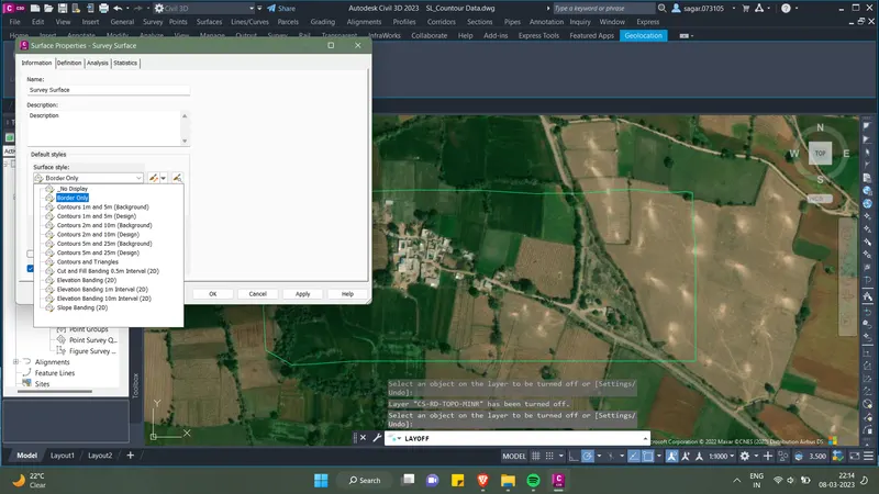
6. Then, you need to change the surface style to border only so that you can draw the horizontal alignment with ease. For this, go to the surface you created in the prospector tab, right click and select surface properties. A pop-up menu appears. There select the surface style as border only.
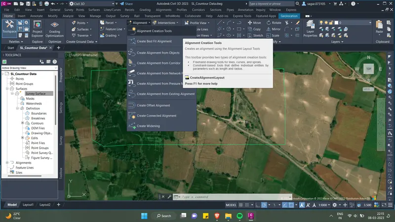
7. Now, taking the geo image as the reference, you can create the alignment. For this, go to Home tab in ribbon, under create design panel, select alignment option. Then select alignment creation tool.
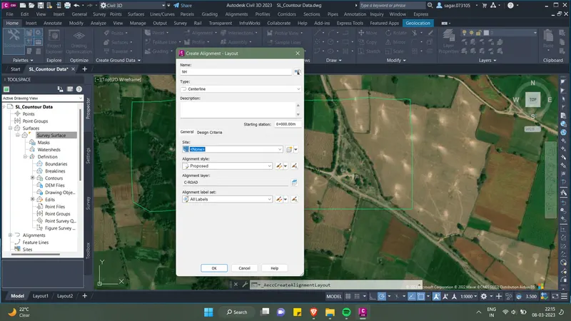
8. From the pop-up menu that appears, rename the alignment, select the alignment style as proposed and select all labels. Click OK. After this another tool panel will appear on the screen.
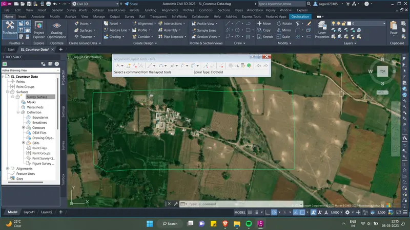
9. From the above tool panel, you can create the alignment by two methods i.e. point of intersection method and element method. For this project I have considered the point of intersection method. In that I have taken tangent-tangent (no curves) in consideration.
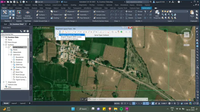
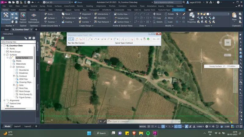
10. Now taking the geo image as reference, draw 1st and then 2nd tangent.
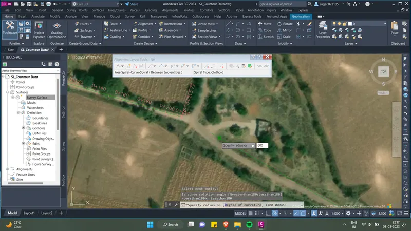
11. Now to provide the transition curve, select free spiral-curve-spiral (between two entities) option as shown in the image below. You have to try for different radius of curve and transition length values to find the best fit alignment for that location. From IRC 38, I have taken the radius value as 600 as transition length value as 35 for 80 kmph speed.
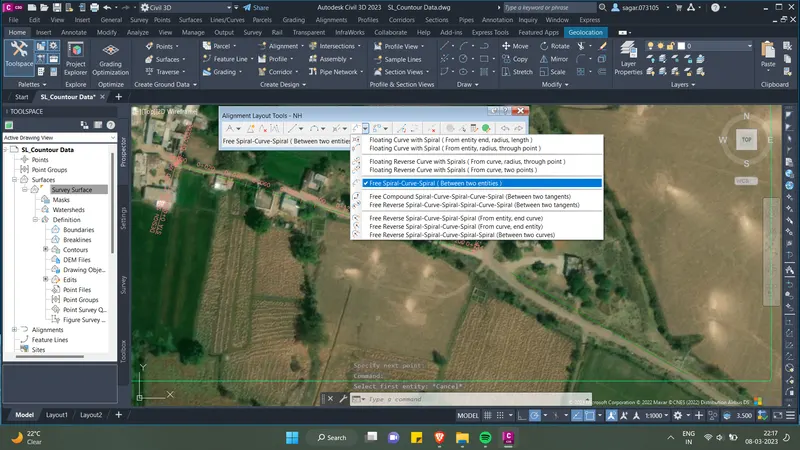
12. After selecting free spiral-curve-spiral (between two entities) option, you need to select the tangents in the same order in which you have drawn them. Then select less than 180 option. After this it will ask the value of radius and transition length, enter that. After this press esc to see the alignment with the curve.
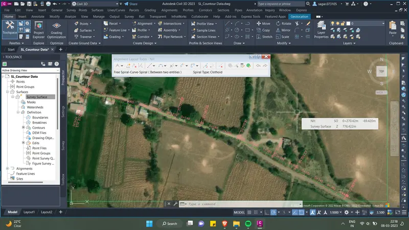
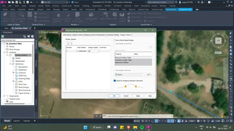
13. Now you need to provide super elevation values. For this, select the alignment, and first go to alignment properties under modify panel in the ribbon. In the pop-up menu go to design criteria and change the design speed to 80 kmph and click OK.
14. Now, in the same modify panel, go to superelevation and click calculate superelevation. Then follow the procedure as shown in the images below.
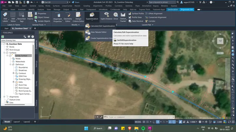
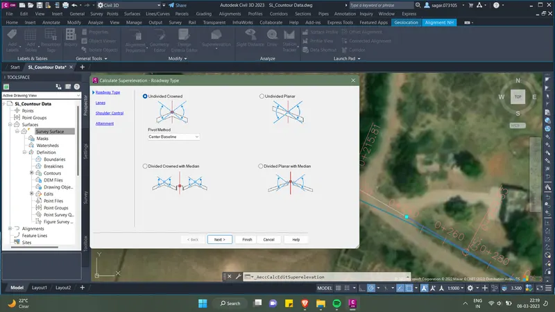
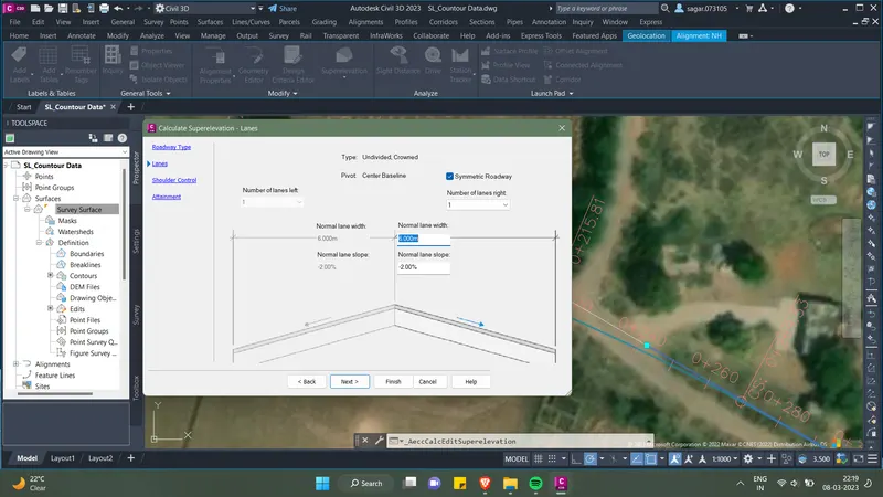
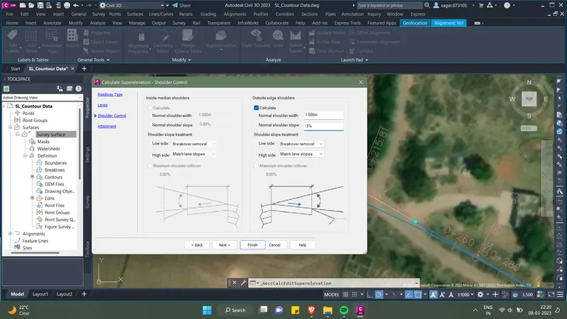
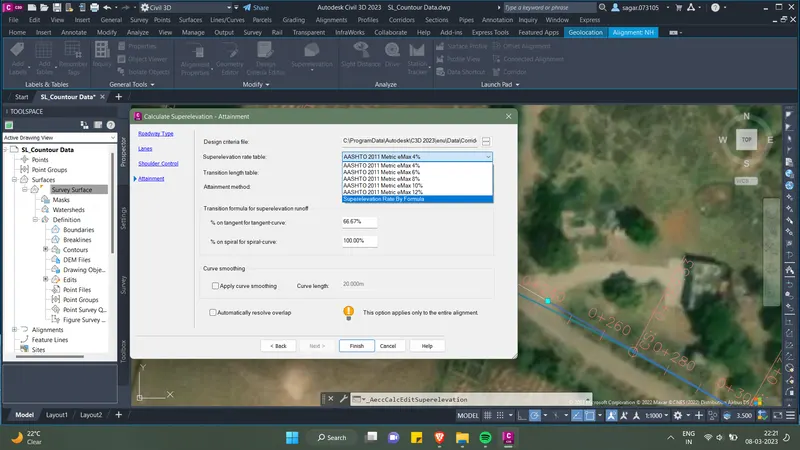
15. From the above images, as you can see that I have considered the values as per the problem statement. At last select superelevation rate by formula. Once everything is done, the alignment will look as shown in the image below. Since the radius of curve is greater than 300, there is no need for extra widening.
- Profile Design in Civil 3D
1. After creating the alignment, to design the vertical profile of the road, go to Home tab in the ribbon, under create design panel, select Profile option. then select create profile by surface. First your have to generate the existing profile details, then you have to give the proposed profile. For this you can go to the menu bar --> Go to profiles --> Click on create profile by layout. I have tried to explain the process by the images attached below-
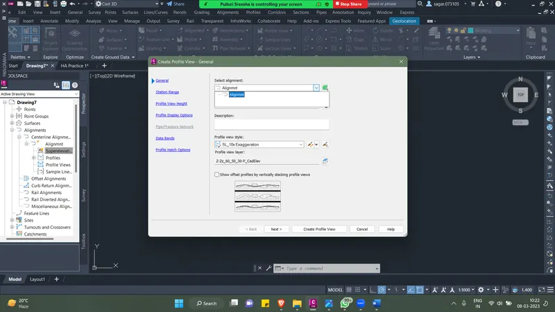
2. A profile creation wizard will appear on the screen. Set the created alignment. Set the profile view style to 10x exaggeration so that all the values can be seen clearly. Then click on Next.
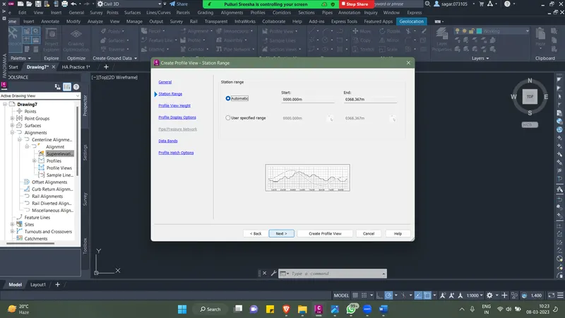
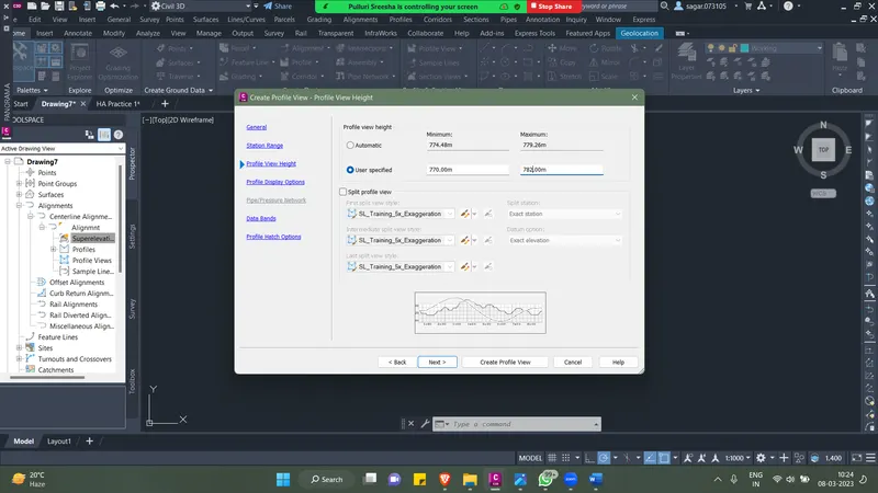
3. Set the station range as per the start and end station points of the alignment. Then set the profile view height.
4. Now set the band style in a manner in which all the profile data is visible in a proper manner.

5. The profile for the existing surface will look something like this. It may be possible that the bands below do not show the proper values at first. But you can set those values by right clicking on the created profile and go to Profile view properties. There you can set the correct values.
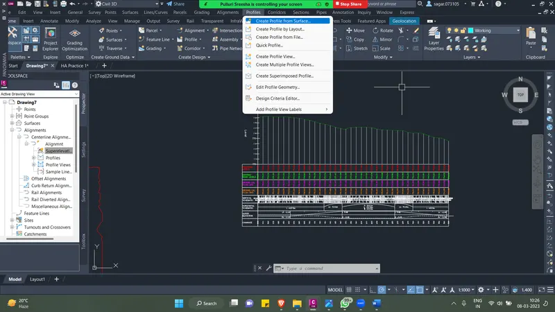
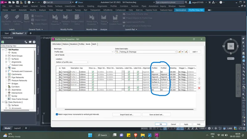
6. Now to set the proposed profile go to Profiles in the Menu bar --> Click on Create profile by layout. A pop-up menu will appear which consists tools to create the profile layout. You can follow the steps as shown below.
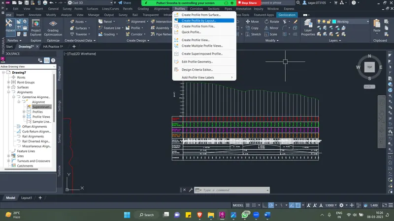
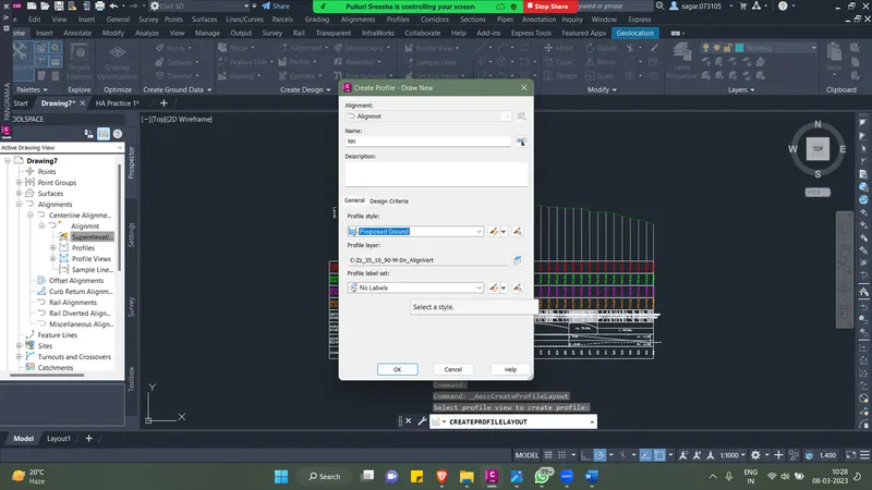
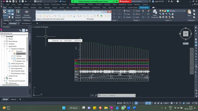
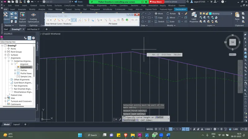
7. Now as you can see that the proposed profile layout is not smooth. So for that right click on the profile layout line and go to profile grid view option, a table will appear as shown in the image below. Here you have to set the K value as per the design speed. Refer to IRC SP 23 for vertical curve for highway. In this refer to table 6. As per our question the design speed is 80 kmph. We always provide the intermediate sight distance. Hence, the K value should be grater than 60.
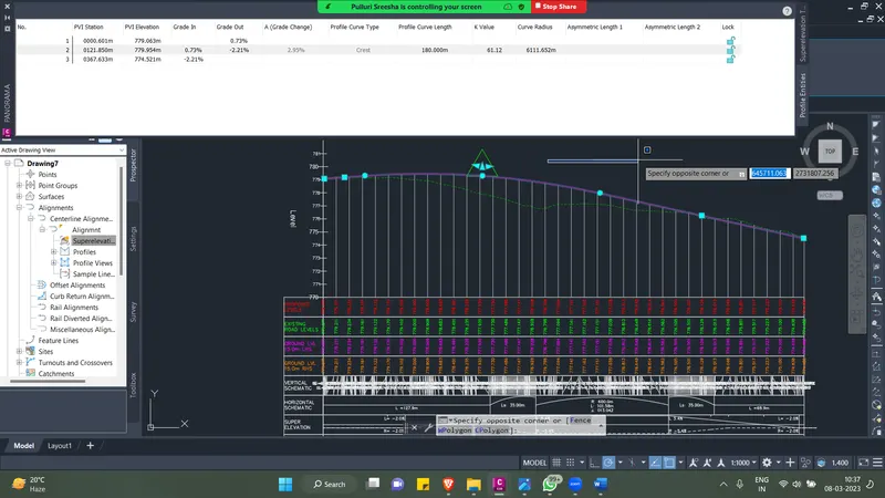
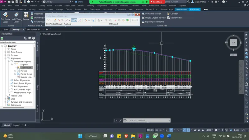
8. Once you achieve the desired profile curve length, you will get the proposed layout.
3. Creation of assembly & subassembly
1. For creating assembly, go to corridor tab in the Menu bar and click on create assembly. From the pop-up menu rename the assembly name, change style and click OK. Then it will ask to specify the baseline point. So give the base point.
2. Now select the base point. The ribbon will show some options, from there Click on tool palette. This will show all the sub assemblies that are required to create the final assembly. Here you can go to lane, shoulder, median etc. options and give their respective properties. Refer to the image below.
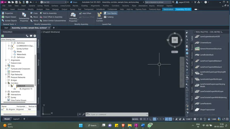
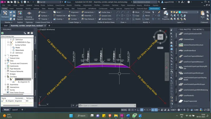
For example, select lane option. Then it will ask to enter the lane properties. Here you can enter the carriage way width and the slope which is to be provided. As per our requirement the CW is 3.5m and the slope is 2% for the concrete pavement. Enter all the required properties an click OK. The lane will be created. Similarly enter the shoulder values. Once all the properties of sections are entered then the assembly will look as shown in the image below.
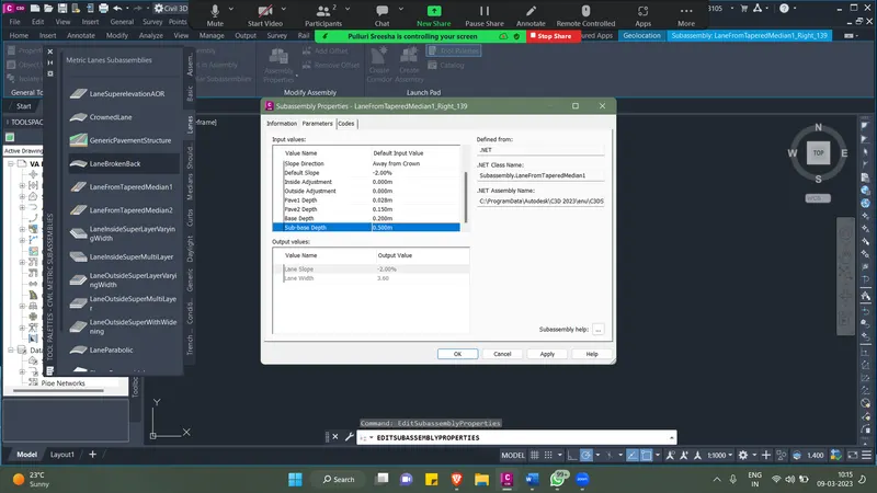
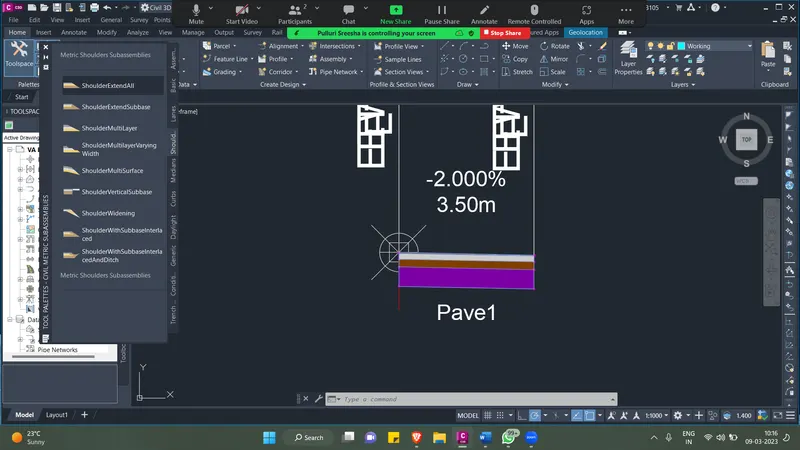
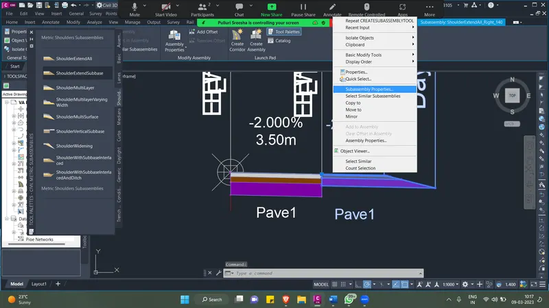
Once the assembly of one side is created, select them, click on mirror, select the baseline point and mirror the assembly to the opposite side.
4. Corridor development
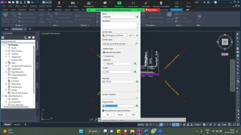
1. For the development of the corridor, again go to corridor tab in the Menu bar and click on Create Corridor. A pop-up menu will appear. Make the following changes in the name, style, alignment, profile, assembly and target surface as shown below. Click OK.
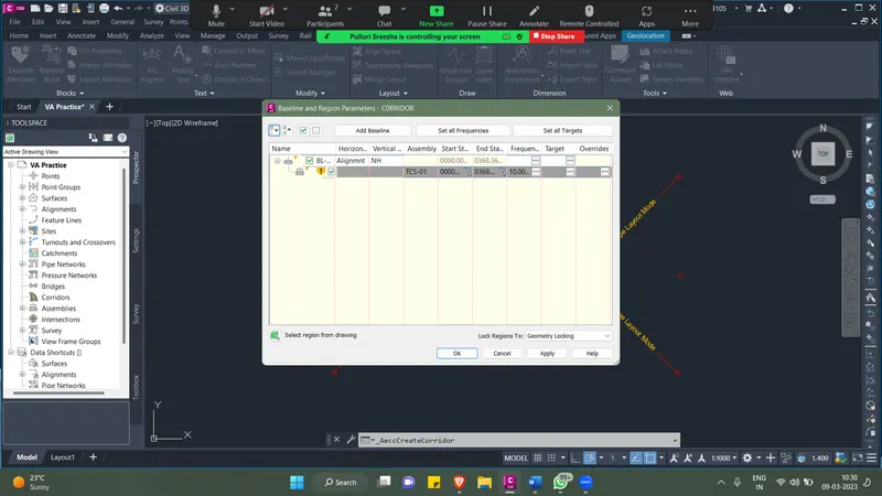
2. The following menu will appear. Apply and click OK.
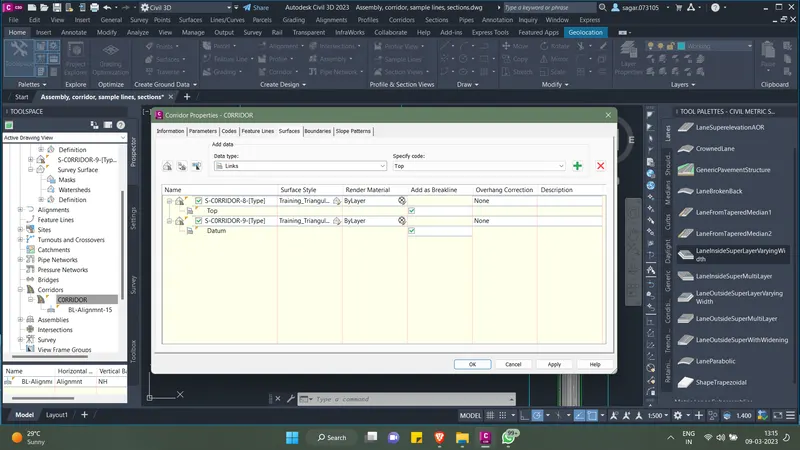
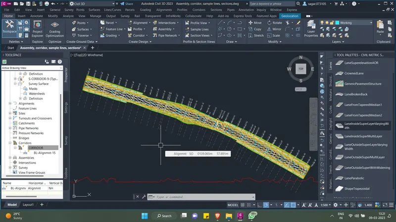
3. Now, in the tool space, under the prospector tab right click on corridor and click on corridor properties. Here you have to create the corridor surface. So, specify surface code as top and datum and check options in "add as breakline" column. Apply and Click OK. After this the corridor will be created as shown in the images.
5. Section lines and detailed cross-sections-
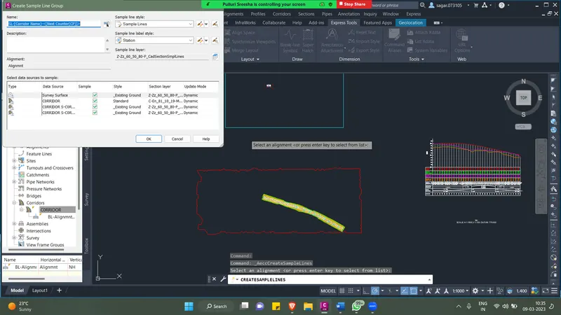
1. To create sample lines, go to Sections tab in Menu bar and click on Create Sample Lines option. Select the alignment for which you want to draw the sample lines. Then a pop-up menu will appear on the screen. Click OK. Then a tool panel will appear on the screen.
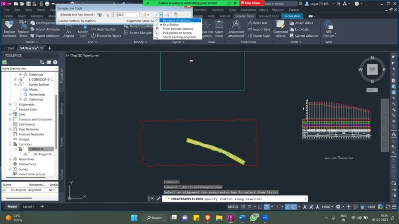
2. From here, click on the sample line creation methods option, select "by range of stations" options. You can use other options too for the creation of the sample lines.
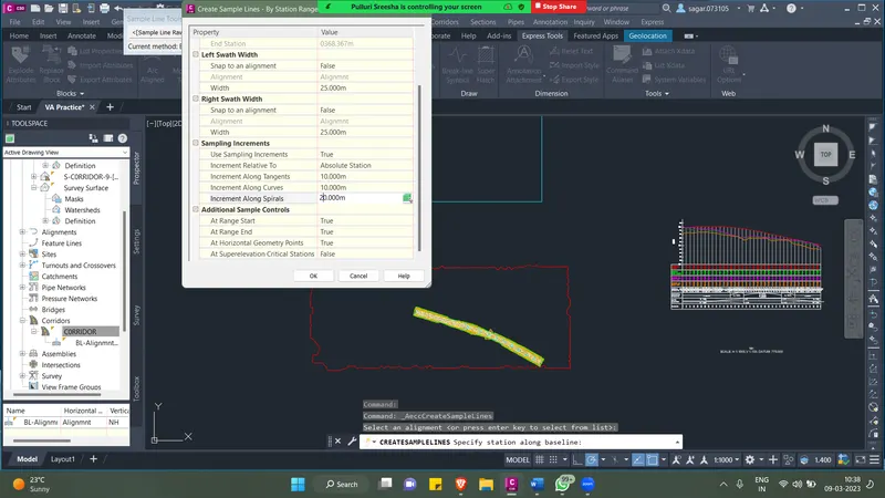
3. Then a menu for creating sample lines "by range of stations method" will appear as shown in the image above. Specify the interval at which you want to give the sample lines, the swath width etc. and click OK. Then the sample lines will be created.
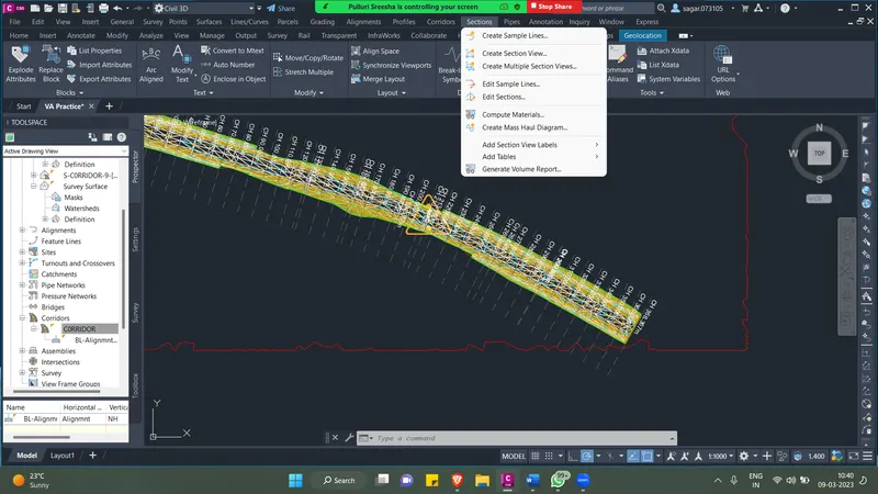
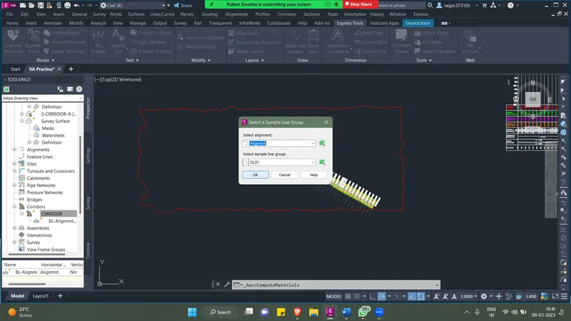
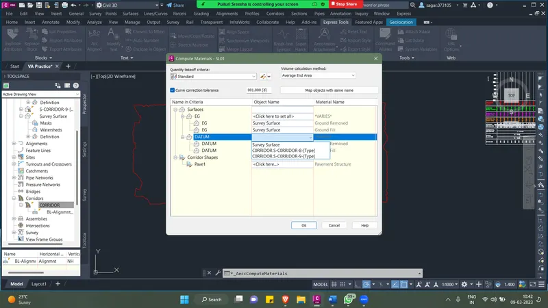
4. Now, before creating the detailed cross sections, you need to compute materials quantities first. So for this, go to Sections tab in the Menu bar, and click on compute materials options. After this you can generate the quantity report.
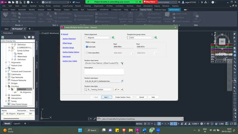
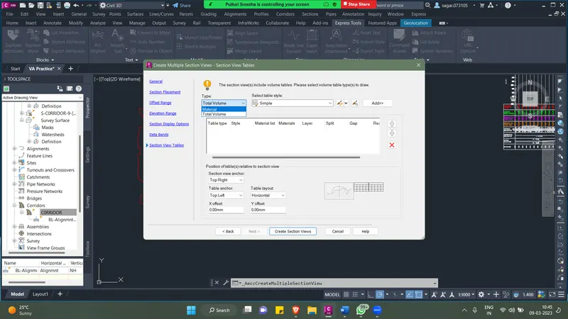
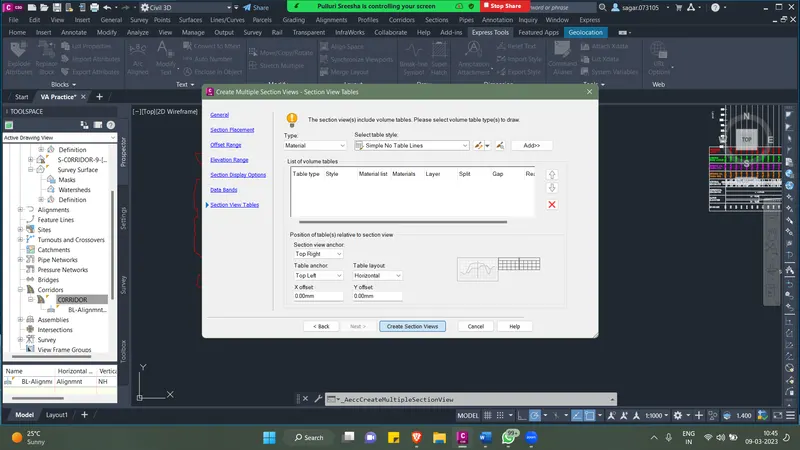
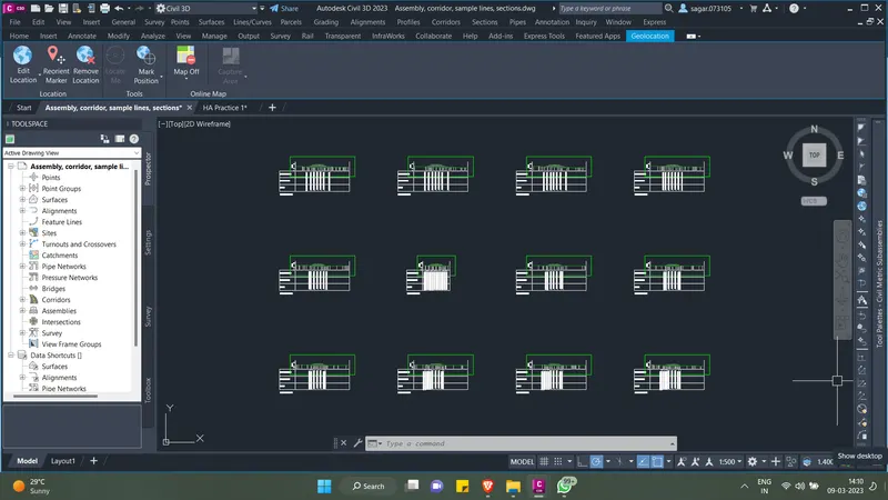
5. Now, go to Sections tab in the Menu bar, and click on "create multiple section views". A section creation wizard will appear. Select the alignment, sample line group that you created. Follow all the steps by clicking next and click OK. The detailed cross- sections for all the sample lines will be created.