Project 1
Answer 1: Create Civil 3D Design File.
Here we have to create all the design file that are required in a roadway design project. The naming of the file will be as follows.
- GDTMRD01 - File which contains surface data.
- ALGNRD01 - File which contains the proposed alignment.
- CLIPRD01- This file will consist of view frames which are required for the creation of sheet sets.
- PLANRD01 - In this file we will create the layout sheet of the complete alignment.
- QTDSRD - This file consist of quantity calculations for this project.
Answer 2: Create surface File & Create Surface by using given Survey Data
- For creating the surface, I have taken the triangles file from week 7 as reference survey data. Now, first we have to create a design file by the name GDTMRD01 which consist of created surface.
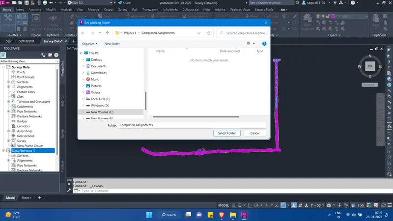
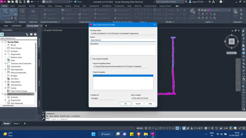
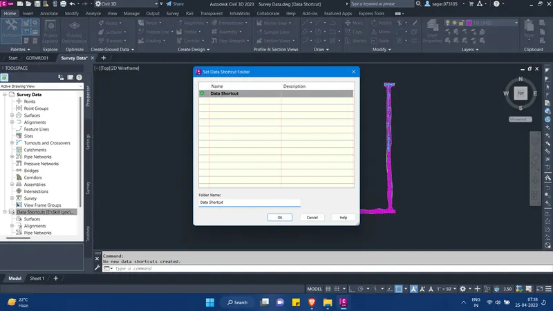
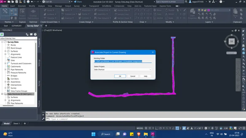
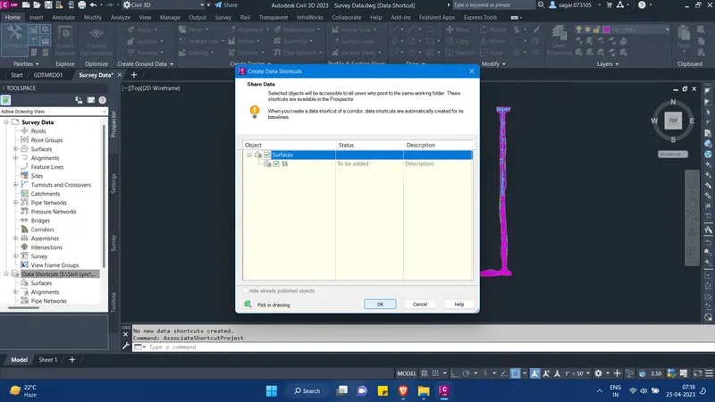
- Now, open the triangles file and create data shortcut in this file. First set the working folder, then create new data shortcut project folder. Then set the new data shortcut project folder. Then associate project to current drawing and then finally create the data shortcut.
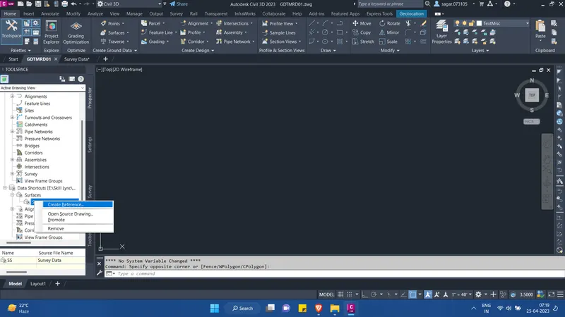
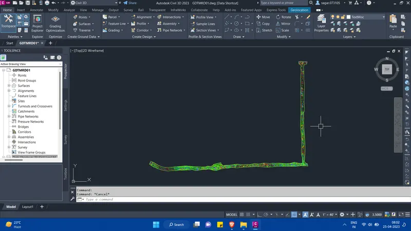
- Now, open the GDTMRD01 file and create reference of the survey surface. Then the surface will be created.
Answer 3: Create Alignment by Using Proper Geometry Standard & apply Superelevation.
- For creating the alignment, create a design file by the name ALGNRD01 using the company's template.
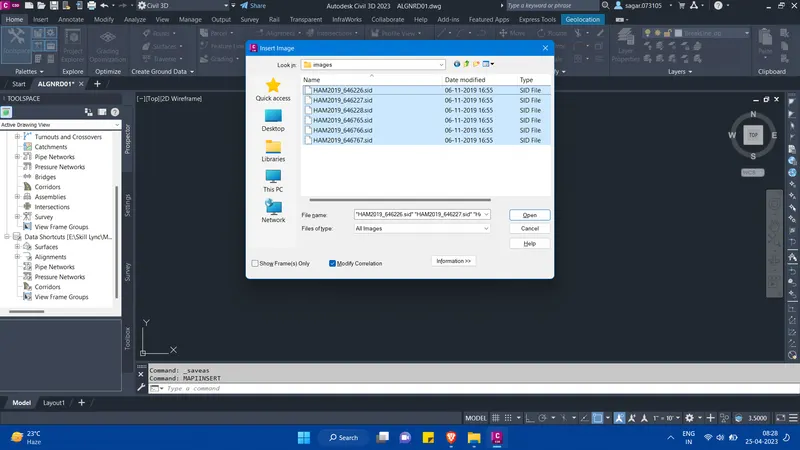
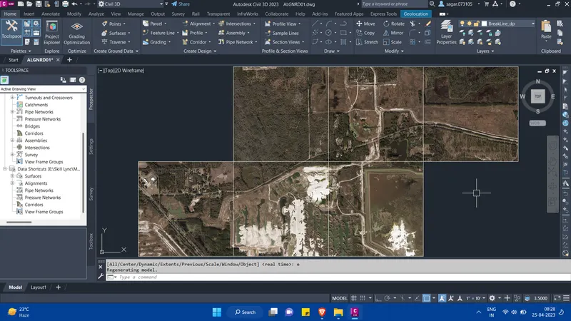
- Then type MAPIINSERT in the command line, select all the images and import the image files. We will use these image file as a reference to create our alignment.
- Type TFRAMES to remove the borders from the images such that all the images act as one single image.
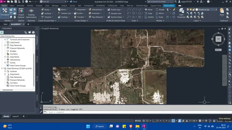
- Now to create an alignment, in the ribbon, go to Home Tab and under create design palette click on the alignment option. There select alignment creation tool option.
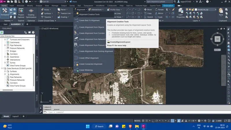
- From the po-up menu that appears, rename the alignment, provide alignment style, set starting station points, set design speed and click OK.
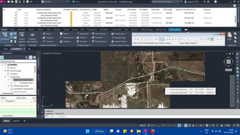
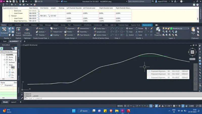
- After this a alignment creation tool palette will appear on the screen. Use these tools to create the alignment as per the images. After the completion the alignment will look like this-
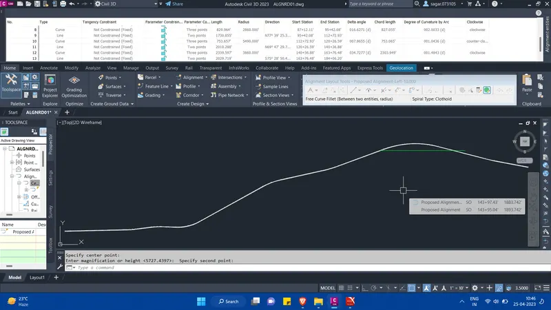
- Now select the created alignment, and go to superelevation option in the ribbon. Here you can calculate the superelevation values for the alignment.
- A superelevation creation wizard will appear on the screen. Follow all the steps and provide the value of crown slope, shoulder slope, pavement type etc as per the standard and click on finish. The desired superelevation will be calculated.
Answer 4: Create View frames & sheet & create separate .dst file for the same.
- Now, before creating view frames and sheets we need to create .dst file which consist of sheet sets and subsets. So, for this open a new file with the company's template. After the file opens press Ctrl+4. A sheet set manager dialogue box will appear.
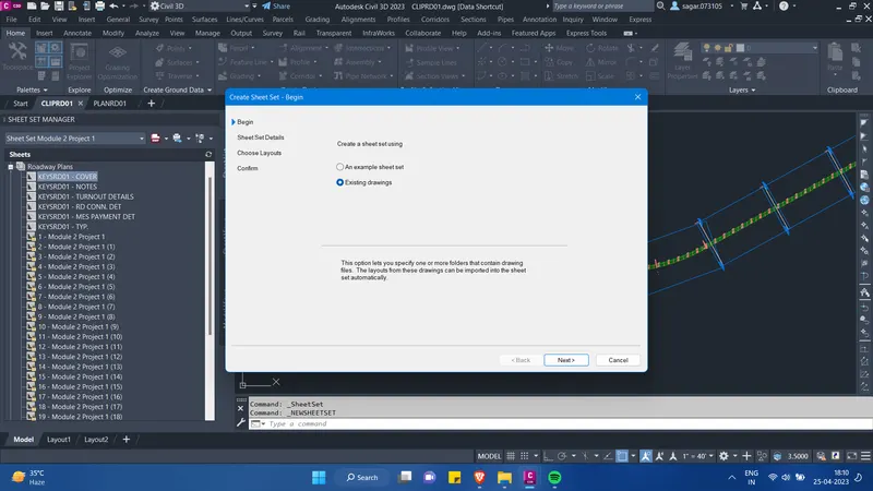
- In the dialogue box, click on new sheet set. A create sheet set dialogue box will appear. Follow all the steps. Under Begin, select existing drawings option and click on next.
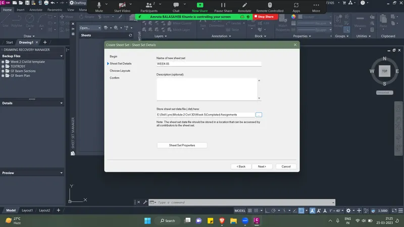
- Then under next step, which is sheet set details, set the desired name and path where you want to save the file and click on sheet set properties.
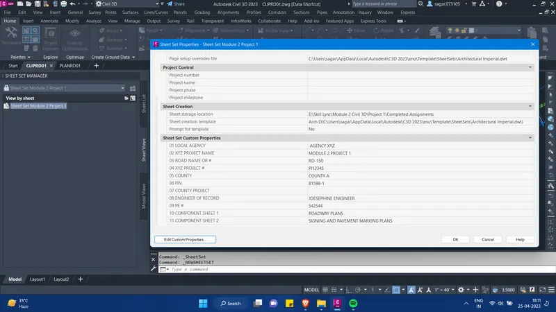
- Now, click on custom sheet set properties option and from the pop-up menu click on "edit custom properties". There edit all the custom sheet set properties as per the company's standards.
- After completing all the process click on finish to complete the sheet set manager. The .dst file by the name Sheet Set Module 2 Project 1 is created.
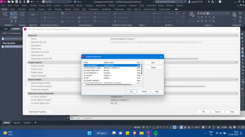
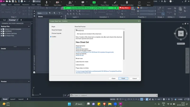
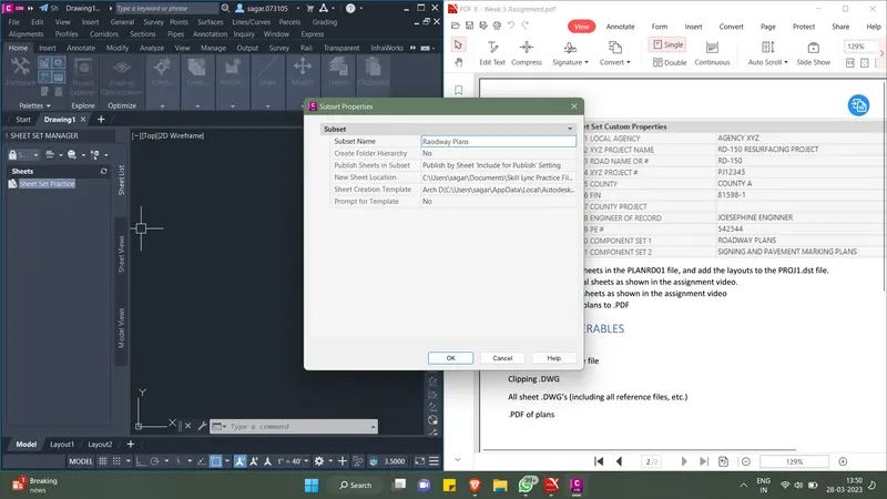
- After creating the sheet set right click on it and click on "New Subset". Then create subsets by the name Roadway Plans and Signing and Pavement Marking Plans.
- Open a new file with the company's template. Click Ctrl+shift+S to save the file by the name Plan Sheet Module 2 Project 1.dwt. Select the file type as dwt and save it.
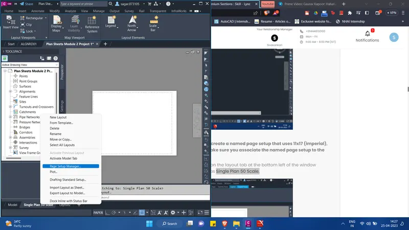
- Now we will rename the layout by the name Single Plan 50 Scale, for this right click on the layout tab at the bottom left of the window besides model and click on Rename. Here name the file as Single Plan 50 Scale.
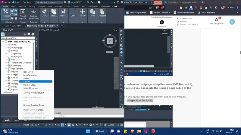
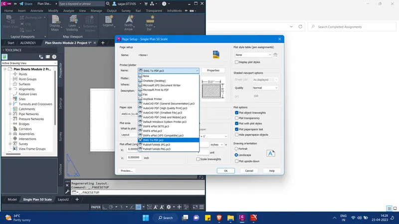
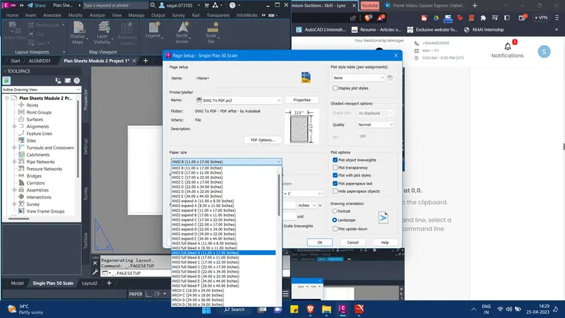
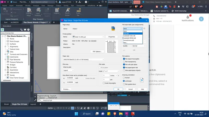
- Then again right click on the layout tab at the bottom left of the window besides model and click on Page Setup Manager. A dialogue box will appear, click on modify. Another dialogue box will appear, here under plotter select dwg to pdf. Set the plot style table to acad.ctb and paper size as 11x17 inches. Click OK, then you can see that the desired page setting has been implemented.
- Open the title block. dwg file which is downloaded from the dashboard. Select and copy the title block to the clipboard. Now come to the plan sheets file and paste it beside your sheet.
- Now since we need to find the center of the sheet first, so type VPORTS command in the command line, select a single view port, type fit and enter. The view port will be fitted as per the sheet. Type LINE in the command line and draw diagonals in the viewport as well as in the title block.
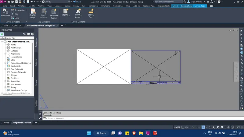
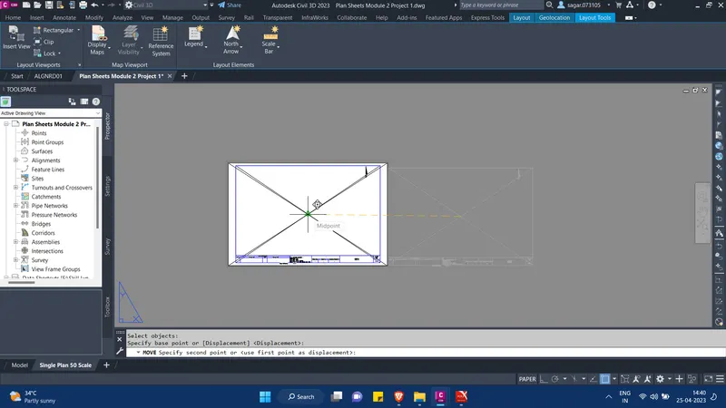
- Now type move in the command line, snap to the center of the title block and drag and drop it at the center of the viewport. Now delete the viewport as well as the diagonals. The title block is perfectly placed at the center of the sheet.
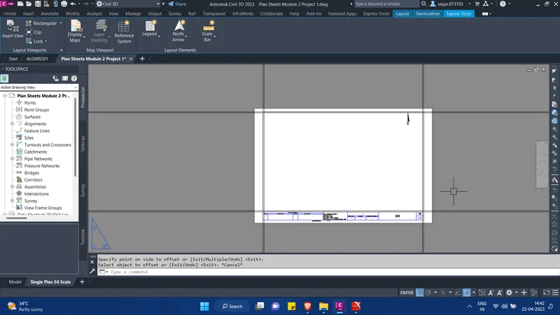
- Now, type XL in the command line and draw construction lines at all the edges of the title block. Then type offset in the command line and give the offset value of 0.1. Offset all the four lines in the inward direction.
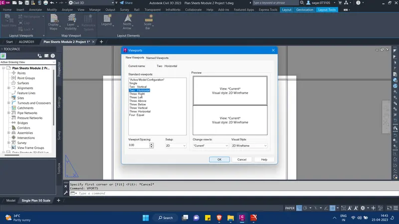
- Then type VPORTS in the command line and from the pop-up menu select two-horizontal viewports and click on OK. Then snap to the opposite corners of the title to place the viewport. After placing the viewport, delete all the construction lines.
- Select each viewport and set the scale as 1"=50' by clicking at the bottom right of the screen as shown in the image below. Also lock the viewport by clicking at the lock sign beside the set scale option.
- Now create a new design file with company's template. Then save the file by the name CLIPRD01. We need to create data shortcut in ALGNRD01 file and then reference it to the CLIPRD01 file.
- So open ALGNRD01 file. Since we have already set and created a data shortcut folder hence we will right click on the data shortcut and select "associate project on current drawing". Click OK.
- Then again right click on the data shortcut and select "create data shortcut". From the dialogue box that appears, check the alignment options and click OK.
- Now come to the CLIPRD01 file and click on alignment option under the data shortcut. There right click on the proposed alignment and click on create reference.
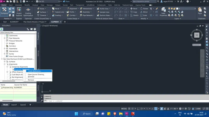
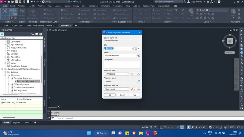
- Then a reference of the proposed alignment will be created in the CLIPRD01 file.
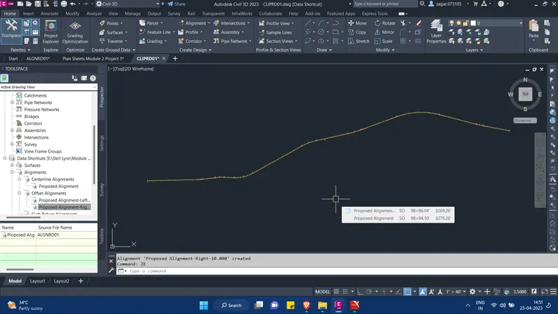
- Now click on "view frame groups" present in the prospector tab in tool space panel. Right click on it and click on "create view frames". Then a dialogue box will appear.
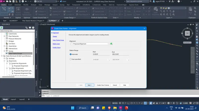
- In sheet settings under sheets option in the dialogue box, select plans only and under view frame placement select along alignment option.
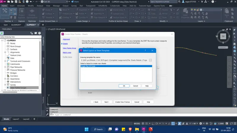
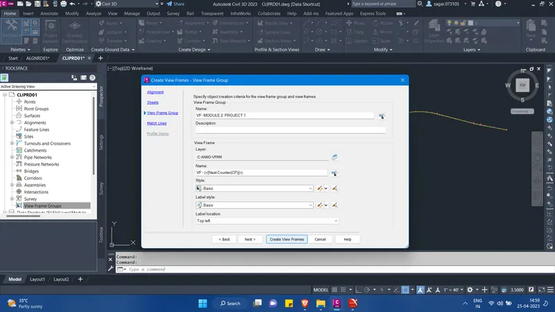
- Follow the steps as shown in the above images. Select the plan only option and select the "plan sheet template" that you created as per the previous steps. Select dual plan 50 scale layout that you created in the previous step. Click OK. Also select the "plan sheet module 2 project 1.dwt" that you created as per the previous steps. Than click next.
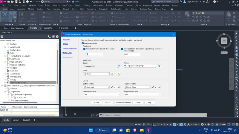
- In allow additional overlapping of view frames under insert match lines, enter 50' and then click on create view frames. Then the view frames will be created along the alignment.
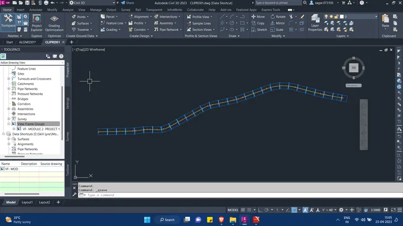
- Then we need to create the data shortcut of the view frame group. For this right click on data shortcut option in the prospector tab and select "associate project on current drawing". Click OK. Again right click on the data shortcut and select "create data shortcut". From the dialogue box that appears, check the view port option and click OK.
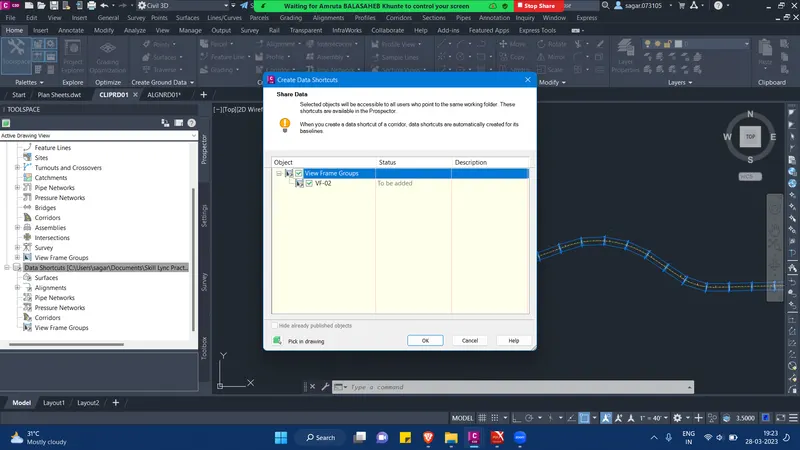
- Now create a new file using the company's template. Name the file as PLANRD01. Then under data shortcut option in the prospector tab, create reference for alignment and view frame groups in the PLANRD01 file.
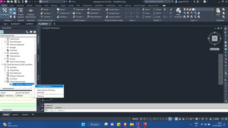
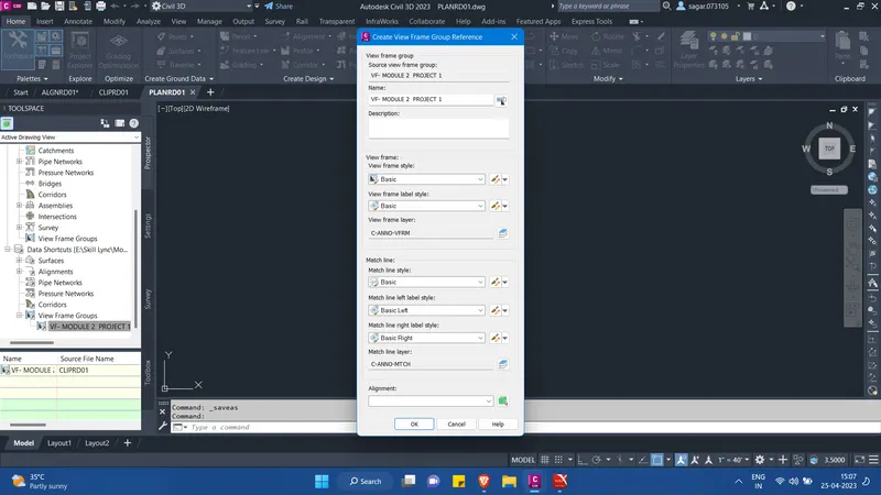
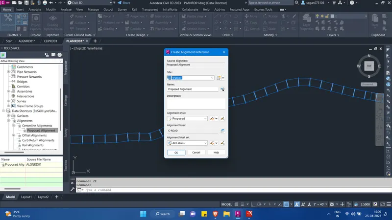
- Now, we need to import the aerial imagery to this file, so for this go to ALGNRD01 file select the aerial images and press Ctrl+C. Then come to the PLANRD01 file, click on Edit option in the menu bar and select paste to original coordinates.
- Set the aerial imagery to the back of the alignment. Hence all the important data shortcut and file are used as reference in PLANRD01 file.
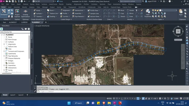
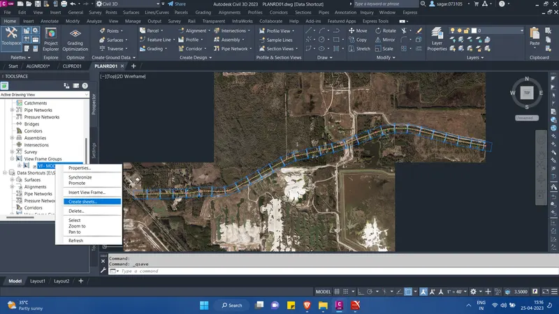
- Now we have to create plan sheets, so for that right click on the view frame group that we created in the previous steps. Click on create sheets. A sheet creation wizard will appear on the screen. Follow the steps as shown in the images below-
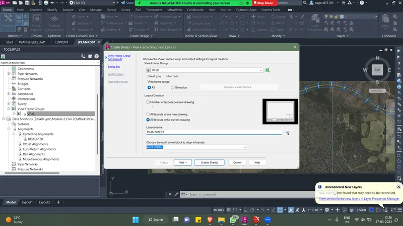
- In the create sheet wizard, under layout creation in view frame group and layouts, select all layouts in current drawing option.
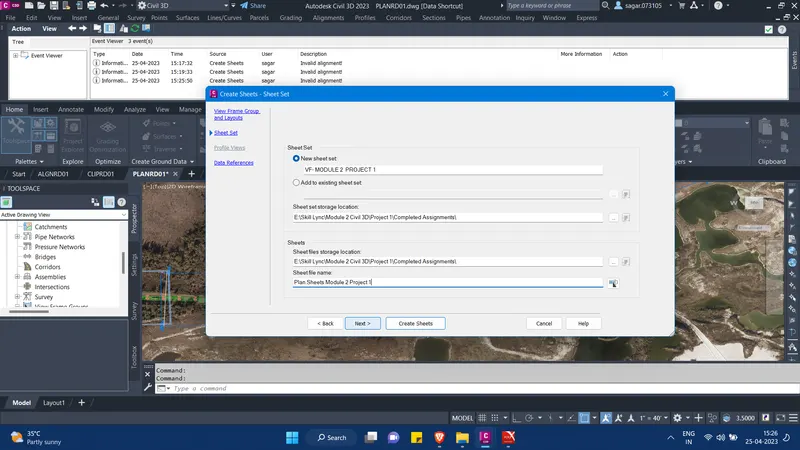
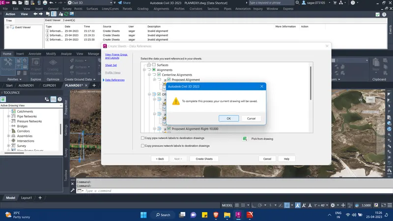
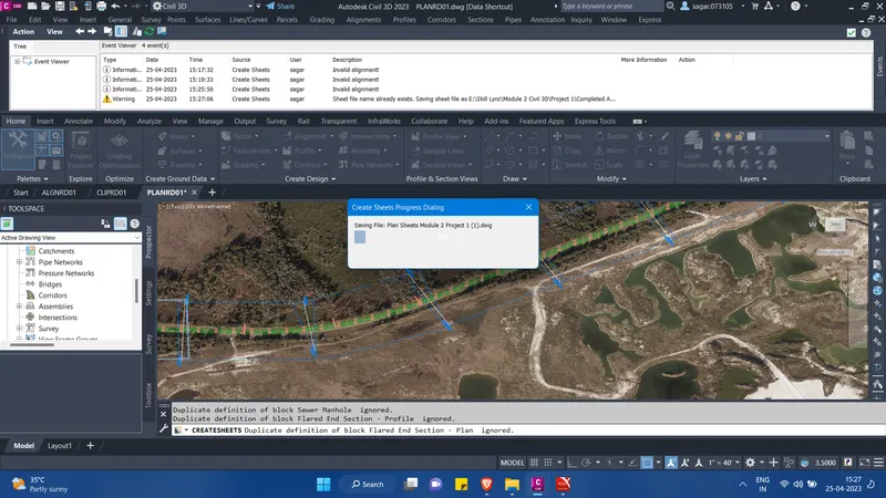
- Hence all the sheets will be generated as per the view frames. After the creation of all the sheets you can place them under the Roadway plan subset. For this, select the first layout sheet, then press Shift and select the last layout sheet. When all the layouts sheets gets selection then drag all of them and drop into Roadway plan subset.
- Now, we also need the key plan, drawing notes attached to our sheet set. So for this, select roadway plan subset, right click and click on "import layout as sheet".
- Then from the pop-up menu, browse and select the KEYSRD01 file. Then check on all the layouts present in that file and click OK.
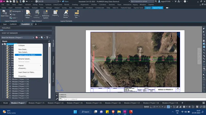
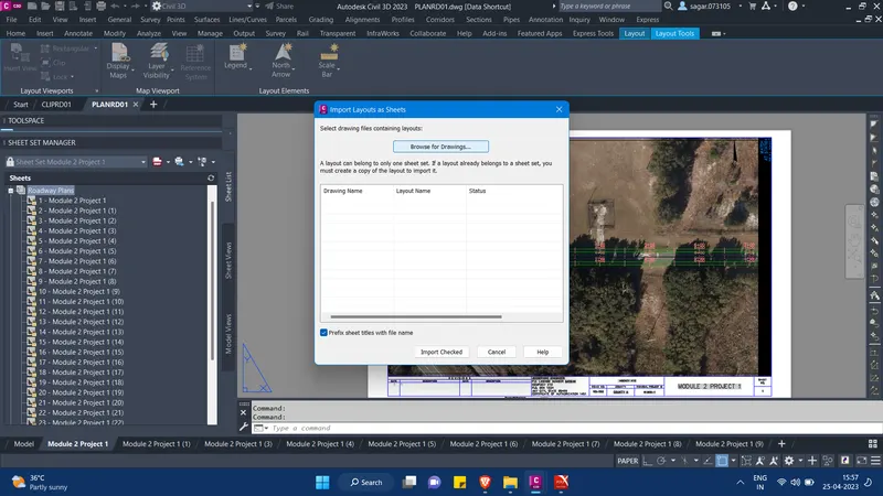
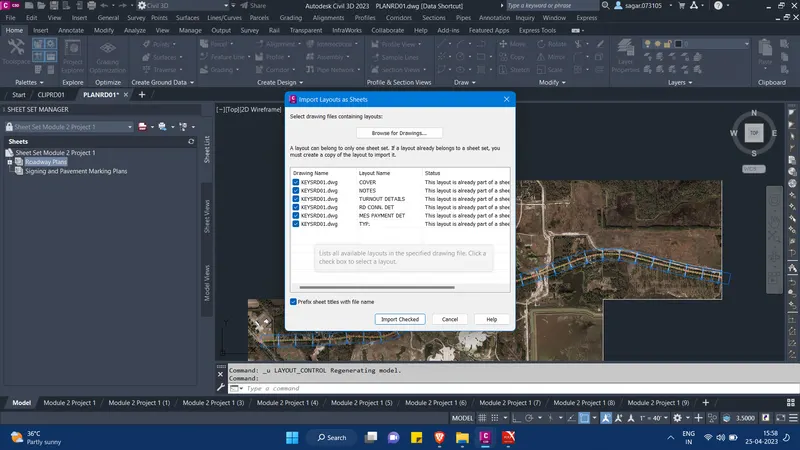
- Then select all the key plan and drawing notes layout sheet and drag it to the top in the sequence in roadway plan subset.
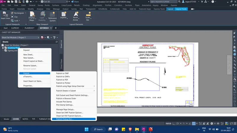
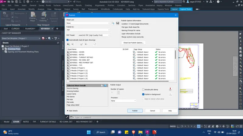
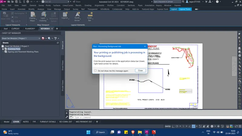
- Now right click on Roadway Plan subset, then go to publish and click on publish dialogue box. A pop-up menu will appear. There set to publish pdf. Set the pdf quality to high and then click on publish. The pdf containing all the drawing sheets will be generated. All the file are attached for the reference.
Answer 5: Workout quantity by using civil 3d.
- Create a quantity file using the company's template. Name the file as QTDSRD file.
- Now, in order to calculate the quantity we need to refer to the total cross-section and edit our QTDSRD file as per the TCS. We need to create the guardrails, guardrails end terminal, shoulders in our file.
- For this, create reference of the alignment in QTDSRD file.
- Select the aerial imagery in ALGNRD01 file, hit Ctrl+C, come to the QTDSRD file. Here go to Edit tab in the menu bar and select paste to original coordinates.
- Now as per the TCS, offset the alignment 10' on both side to create existing pavement width. Then offset 12'on both sides from the centerline to show widening. The effective width of widening is 2'. Then offset 18' on both sides from the centerline to show soil stabilization area. The effective width of soil stabilization is 6'.
- Then we have to hatch the area of widening, soil stabilization, pavement surface with their respective layers.
- We can refer to the aerial imagery and find out the location for guardrails and guardrail end terminals.
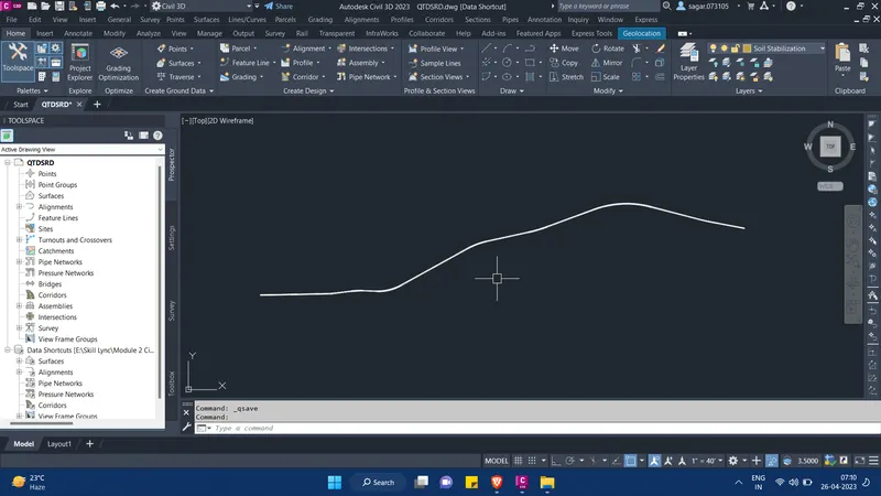
- Now we need to fix the pay items. The pay items .xml file has been provided with the deliverables. The location of the .xml file is - E:\Skill Lync\Module 2 Civil 3D\Project 1\Downloaded from dashboard\Skill-Lync\Designing a Roadway Project Using InfraWorks, Civil 3D, and Map 3D\PROJECT_01\CADD\Roadway\eng_data\AGENCY.
- Now, in Civil 3d, go to Analyse tab in the ribbon and click on "QTO manager". Then a pay item manager dialogue box will appear.
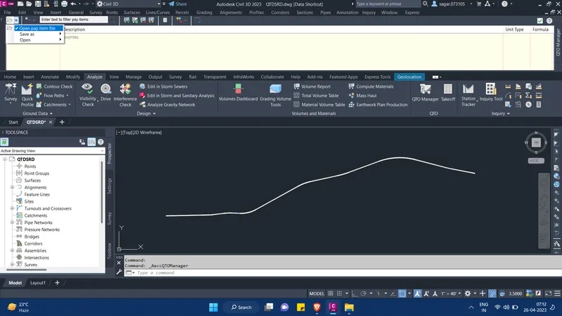
- In the dialogue box, click on open pay item file option as shown in the image above and select the xml file. Select the pay item file and the pay item category file. Select the file format as xml.
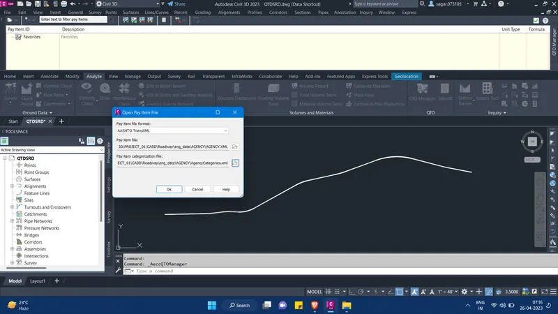
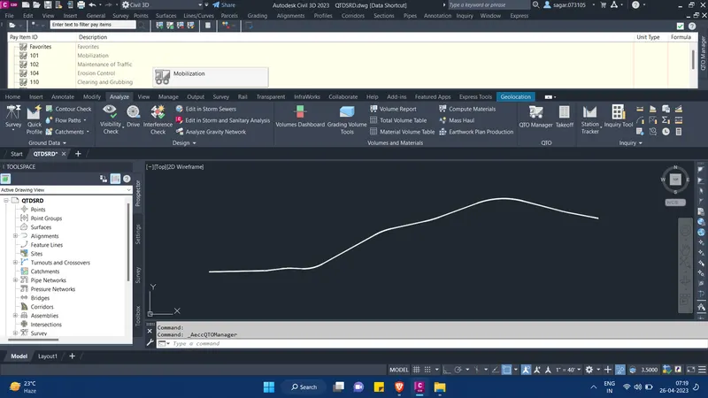
- Now to assign appropriate pay items to the AutoCAD objects, we again need to refer the total cross-section of the road and understand how many items are there based on their units i.e. m3, m2 etc.
- Each item has a unique item ID, and we have to link these items to the objects present in the alignment. By using the search bar at the top, we can find any item in the list by typing the name or the ID.
- We can also search for the pay item ID in our excel sheets for ease. For eg- for soil stabilization, the pay item ID is 0160 4.
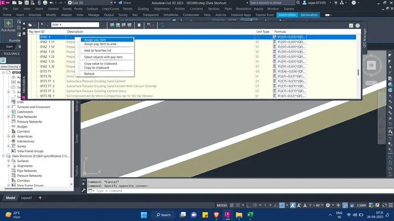
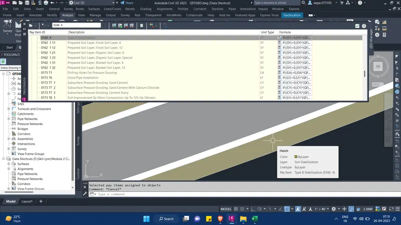
- So we will select the hatch of soil stabilization, then right click on the respective item and select "assign pay item". Then the pay item will be added to the selected area.
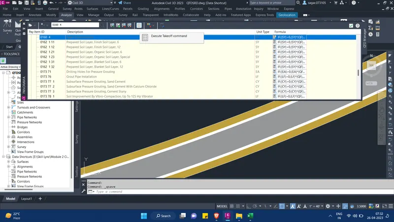
- Now select the pay item 0160 4 and click on "execute takeoff command" to find the quantity.
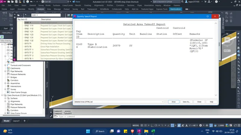
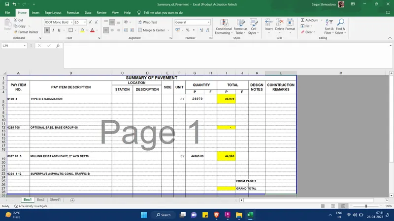
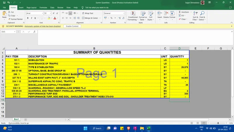
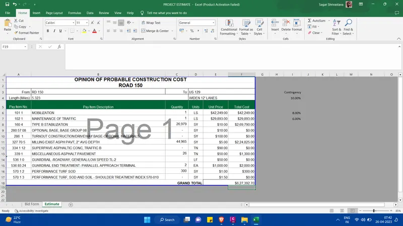
- Then we need to bring this report to out respective excel sheet. We also have to link all the excel sheets simultaneously. Different pay items have separate excel sheets which should be linked to the summary of quantities. And the summary of quantity sheet should be linked to Project Estimate sheet. Then finally the project estimate sheet should be linked to the Bid Form.
- Once all of this is done then then we only need to update the values of the pay items in those separate sheets. It will automatically be updated in all the other sheets.
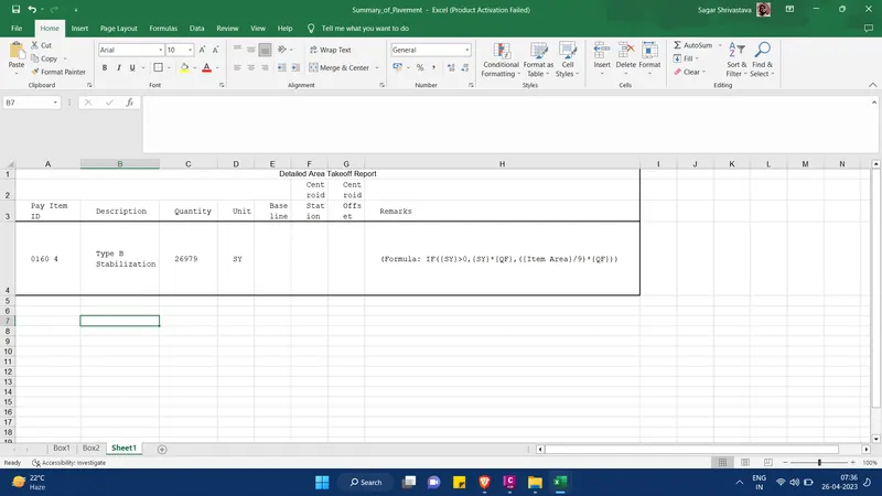
- Similarly, we need to follow the same steps for all the pay items. We need to calculate the quantities and bring them to the respective pay item's excel sheets so that our summary of quantities sheet, project estimate sheet and bid forms will be updated.