Project 2
PROJECT 02 ASSIGNMENT
- We will start the project by creating the surface. So, for this we will open the triangles file which is present in the survey folder.
- After the file opens we will first check the drawing object type. In this case the drawing objects are 3d faces.
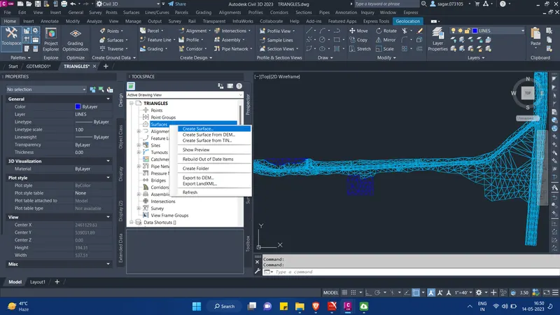
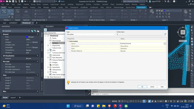
- Now, in Tool Space under Prospector Tab, right click on the surfaces option and click on "Create surface". Then in the pop-up menu give the surface name as existing ground.
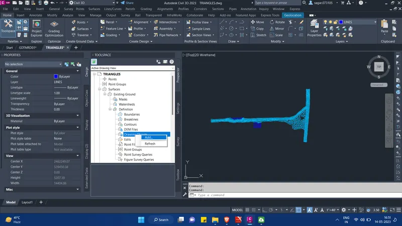
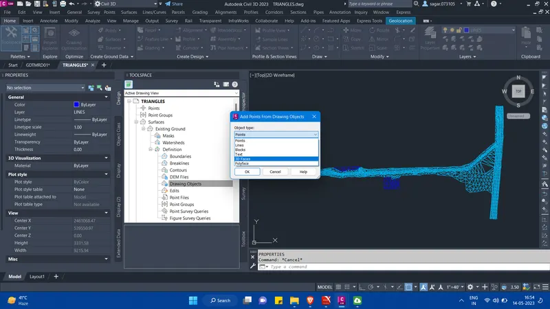
- Then in the prospector tab, expand the created surface under which expand the definations options and then right click on drawing objects option. Then click on add. Then from the pop-up menu, under object type select 3d faces and click OK.
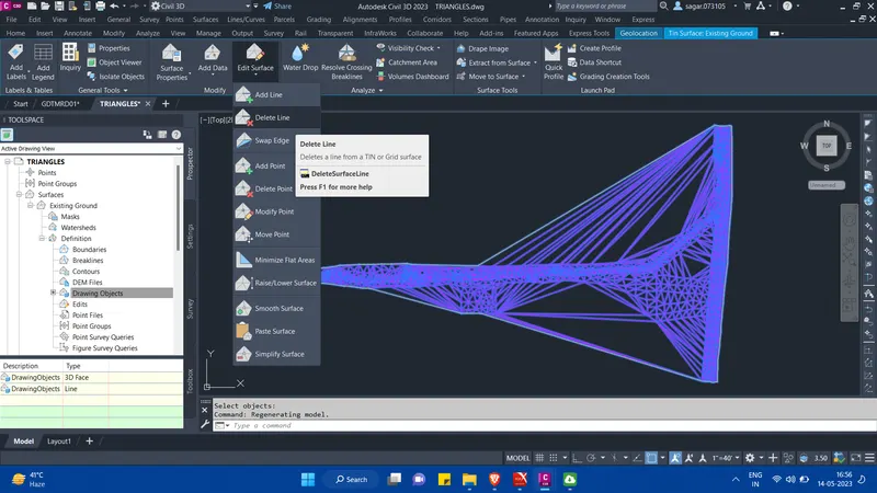
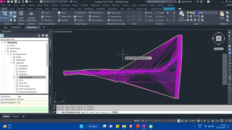
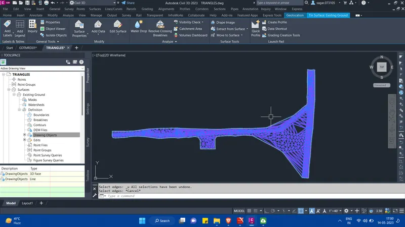
- Then we can further edit the extra lines in the surface. For this, first we need to select the surface. Then from the ribbon go to edit surface and click on delete line. Then press f on the keyboard and start selecting near the outer region of the surface as shown in the image below.
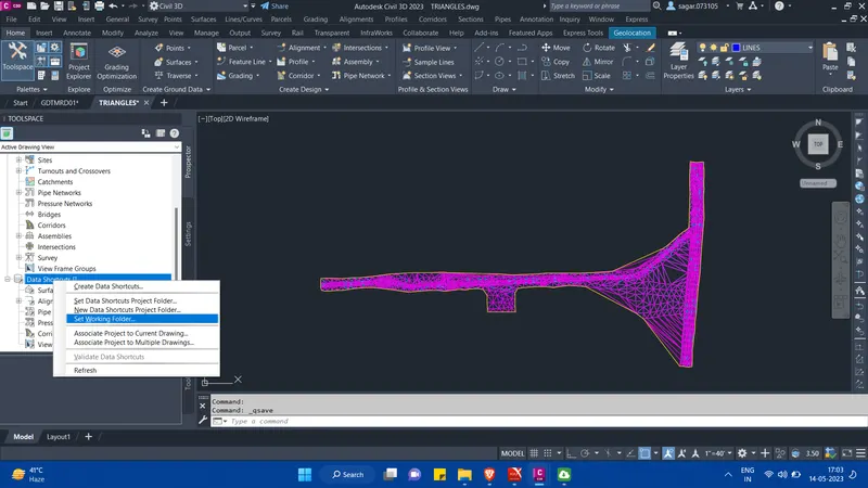
- Then we need to create data shortcut of the surface that we just created. So for this, we need to go to data shortcut option under the prospector tab. There we need to select "set working folder otion" as shown in the image below.
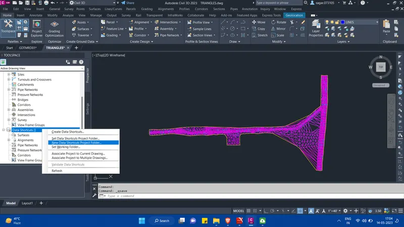
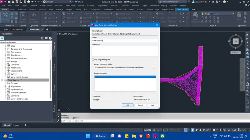
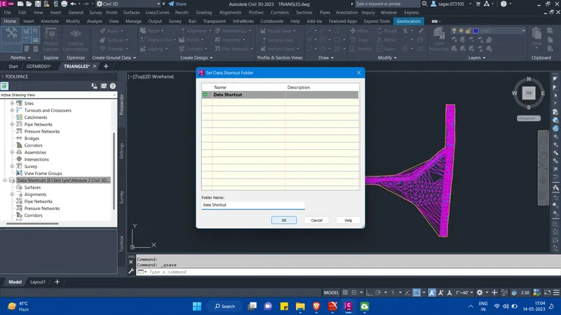
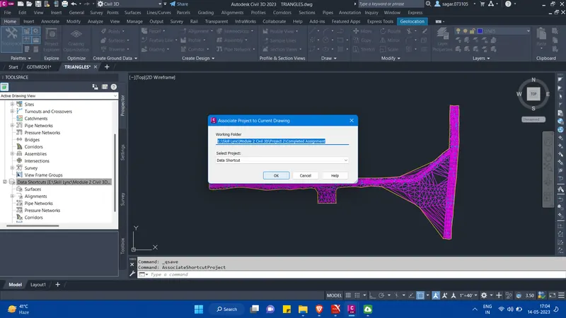
- Then we will select "new data shortcut project folder" and from the pop-up give the name of the folder as data shortcut. Then set the new data shortcut project folder. Then associate project to current drawing and then finally create the data shortcut.
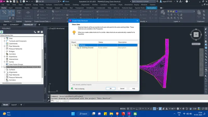
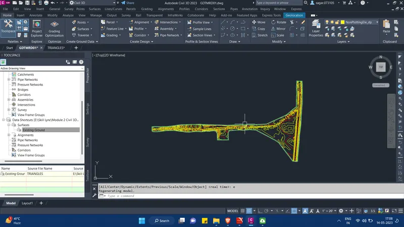
- Now, create new file by the name GDTMRD01 and create reference of the survey surface. Then the surface will be created.
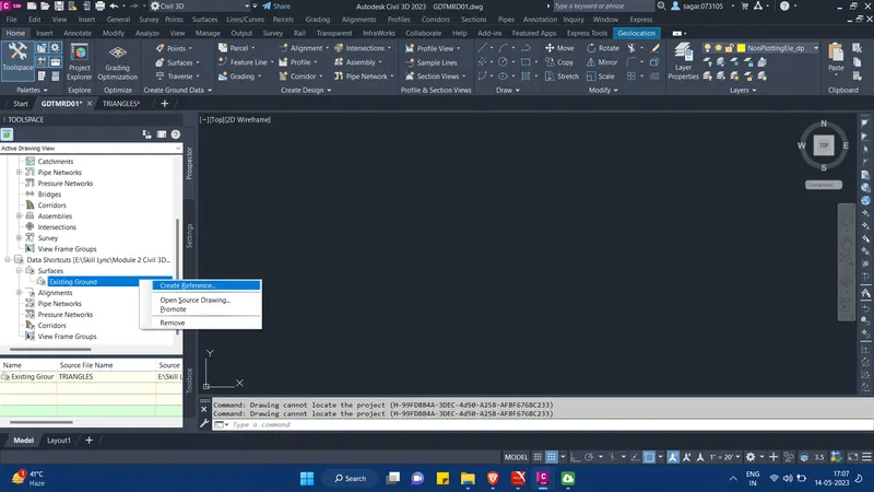
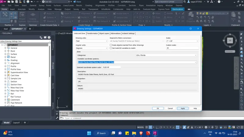
- Also set the co-ordinate system to FL83-NF. Click OK.
- Now, after the creation of surface, we will create the alignment and profile of the road. For this create new file by the name ALGNRD01 and create reference of the survey surface. Set the co-ordinate system. We also need to create XREF of the TOPORD01 file in our ALGNRD01 file. We will use the data from TOPORD01 file while creating the alignment.
- Now for the creation of alignment, click on alignment option under create design palete in Home tab. Then click on alignment creation tools option. In the pop-up menu give the name of the alignment and set the desired alignment styles. Set alignment style for centerline as well as offset aligements.
- Then go to design criteria option and set the design speed to 45 mi/hr. Then click OK.
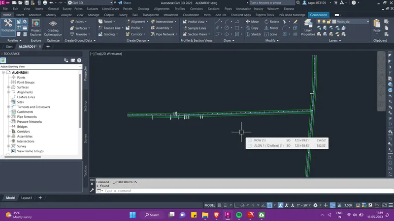
- A tool palete will appear on the screen. Use these tools to create the desried alignment. After creating the alignments for both the roads it will look like this.
- After the creation of the alignment, we need to provide superelevation to it. So for this, select the alignment for which you want to provide the superelevation.
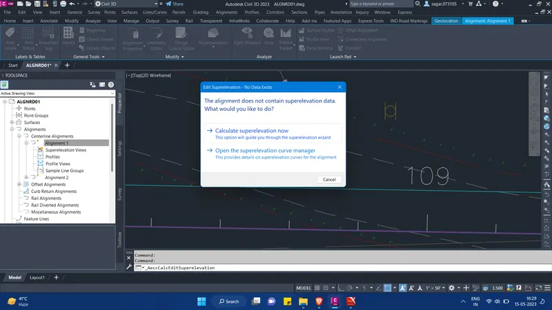
- Then from the contextual ribbion click on the superelevation option and then click on calculate superelevation now. Then follow the steps as shown below.
- Then as per the TCS, select the pavement type. Then click on Next and provide the lane width and lane slope. Then click on Next and provide the shoulder width and shoulder slope.
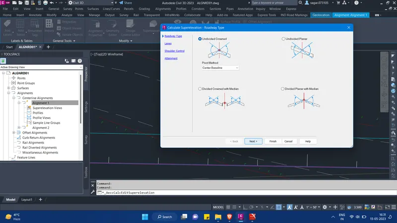
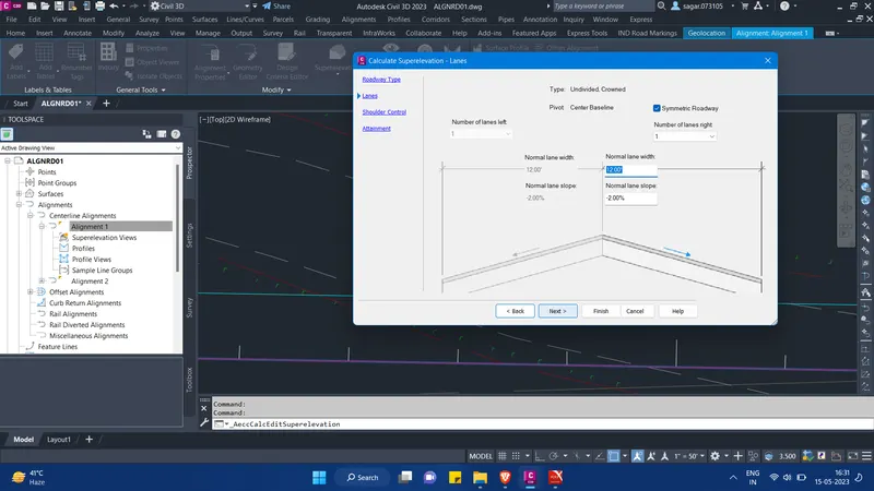
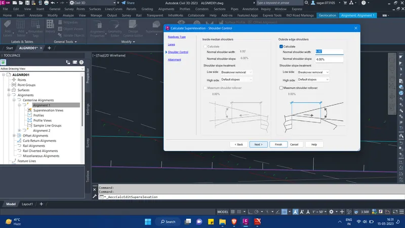
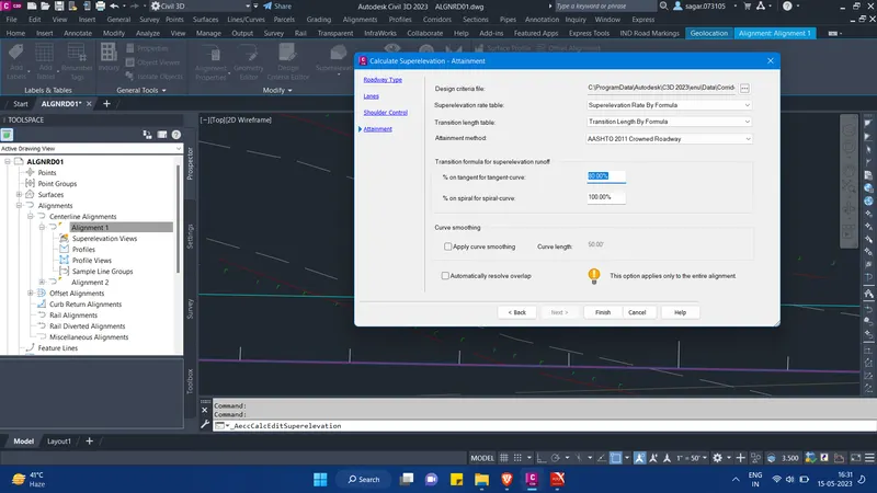
- Then finally select the standards for superelevation design and click on finish. Then the superelevation will be provided to our pavement. Similarly we have to provide superelevation to alignment 2 also.
- Now further we need to draw the profile for both pavements. So for this, under create design palette in the ribbion, go to profile and select "create surface profile".
- From the pop-up menu select the alignment 1 and the existing surface. Click on add to link the existing surface. Then click on "Draw in profile view".
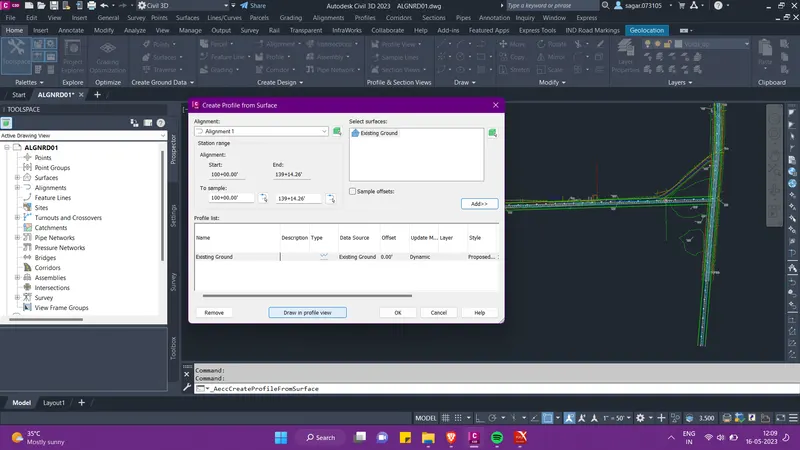
- Then a profile creation wizard will appear. Follow the steps as shown in the image below.
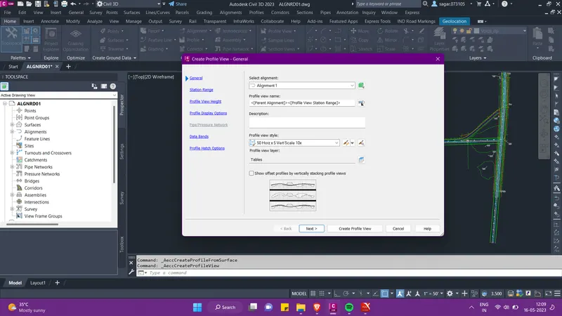
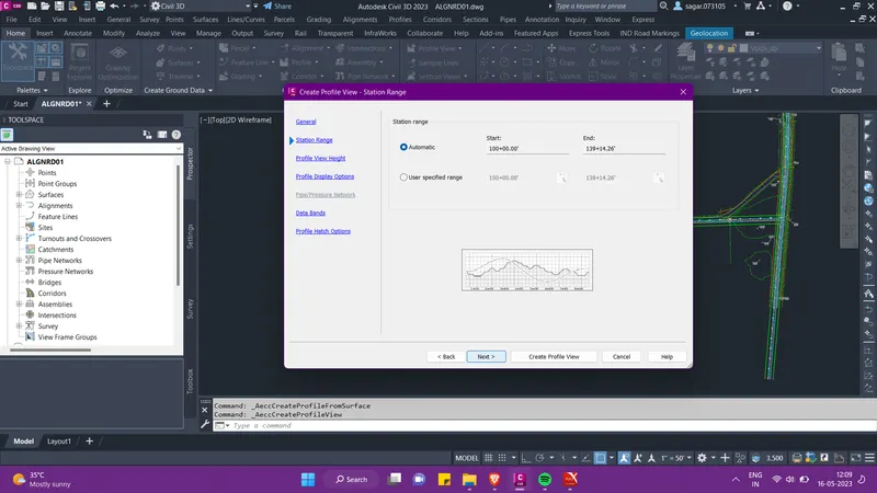
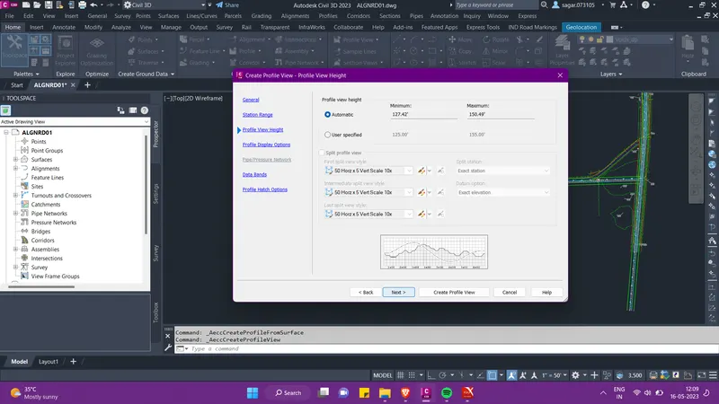
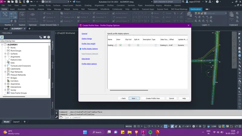
- After setting the profile view height, station range, band styles and display options click on create profile view. Then click on the screen to place the created profile view.
- Similarly we have to created surface profile for the alignment 2 as well. It is suggested that before we create the surface profiles, we should create a frame with the help of XL command so that we can place the profile views systematically at their juctions.
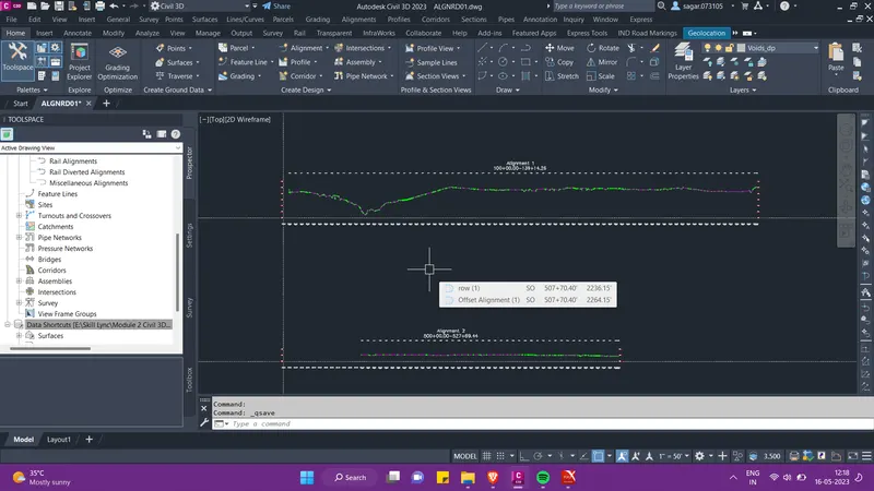
- After the creation of surface profile we need to create the design profile for both the roads. So for this, under create design palette in the ribbion, go to profile and select "profile creation tools".
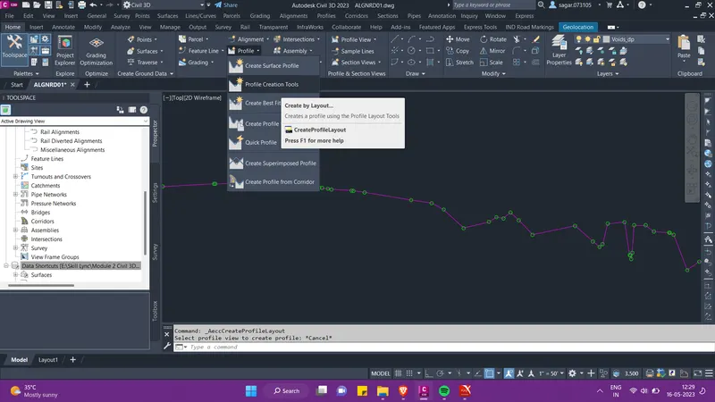
- Then we need to select the profile view to create design profile. We will first slect the profile view for alignment 1.
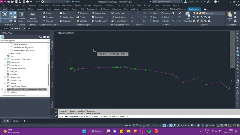
- Then a pop-up menu will appear as shown in the image below. Here set the profile style and click on OK.
- Then a profile creation tool palette will appear on the sreen. Here select the tangents option. Now select the starting point of the existing ground, draw a tangent uptill the end point of the existing ground.
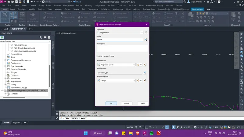
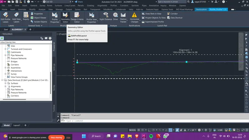
- Then we have to provide PI points to the tangent that we just created. So provide the PI in such a way that it is sufficiently above the existing ground.
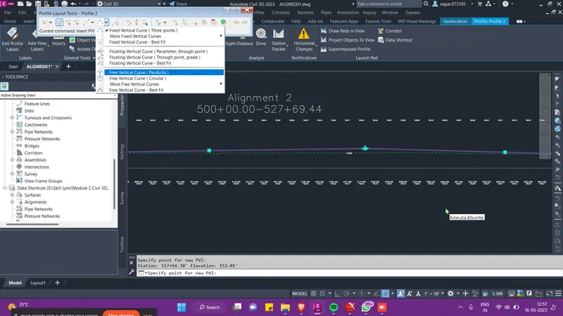
- Then follow the image below, go to the option as shown and select free vertical curve (parabola) option. Then select the tangents one by one and provide the desired curve value.
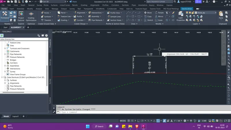
- Then you can see that the profile view with the desired vertical curve has been created. We have to follow the same procedure and create the design profile for the alignment 2.
- Other than the profile view for centerline alignment, we also need to create the profile views for offset alignments of alignments 1 and 2. The software will use all these to create proper corridor.
- Then we will create data shortcut of ALGNRD01 file, which we will use as reference in our MODLRD01 file.
- Then after the creation of alignment and profiles, we will now create assemblies and sub-assemblies and then further we will create the corridor with the help of that.
- So first we will create the MODLRD01 file, then we will create reference of all the centerline and offset alignments, existing ground along with the profiles. We will also check if the co-ordinate system is set properly in this file.
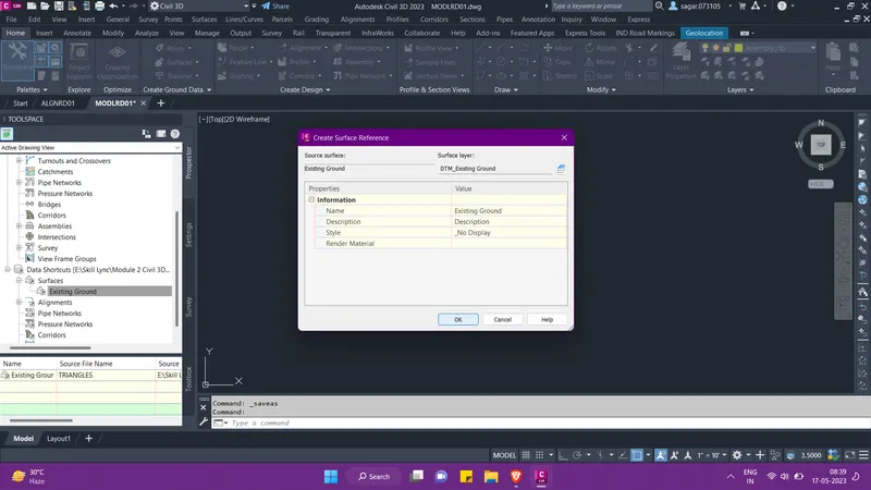
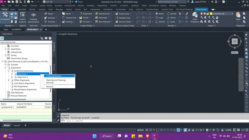
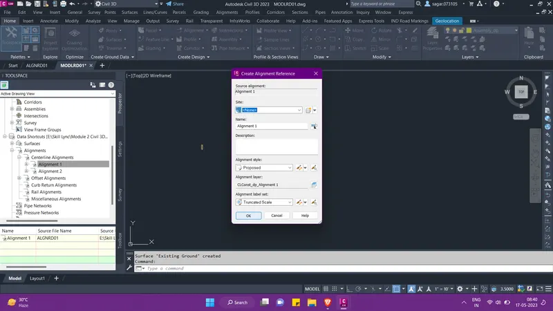
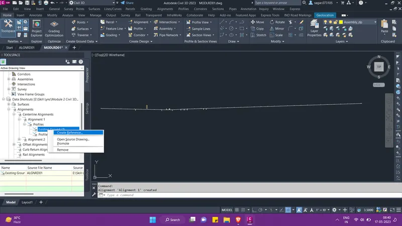
- We can create a rectangle so that we can keep all our assemblies and sub-assemblies in one place. Then go to ribbion and under the create deisgn palette, click on assembly option and select "create assembly".
- Give the name TCS-01 to the created assembly. Set the assembly style. Then click on OK.
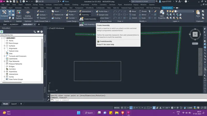
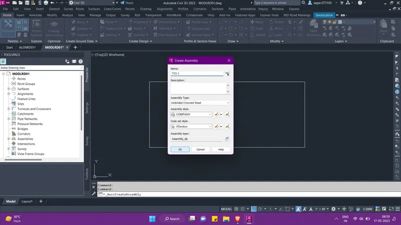
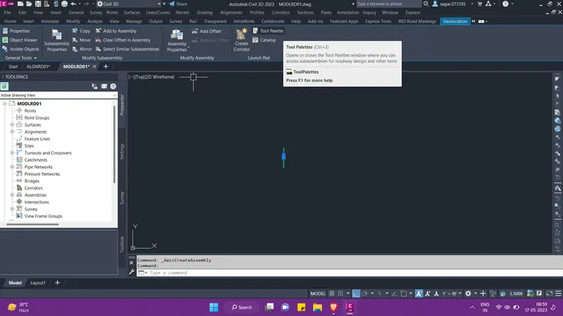
- Then the assembly will look something like this. Select it and then form the contextual ribbion select tool palette option to add sub-assemblies to this assembly.
- We have to refer to the assignment.PDF to get an idea on how the TCS will look.
- For this project I have taken the TCS -01 for alignment 1 and TCS-02 for alignment 2.
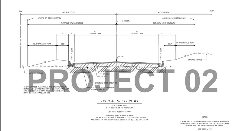
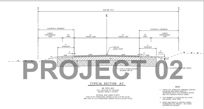
- Then select the desired sub-assemblies as per the images above and edit there properties from the properties window as shown below.
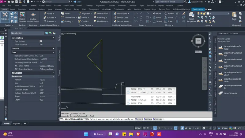
- Then the TCS-01 and TCS-02 assemblies will look something like this.
- During the creation of intersection in the corridor, we will require some variation of both TCS 01 and 02. So i have also created them as per the condition at the junction. Refer to the images below.
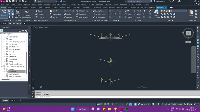
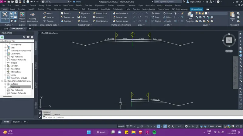
- Now we will proceed to create the corridor for both the alignments. We will create one corridor for both of them and we will use the centerline alignment to create the connected alignments for inersection modelling.
- So for creating the corridor, go to ribbion and under the create deisgn palette, click on corridor option and select "create corridor".
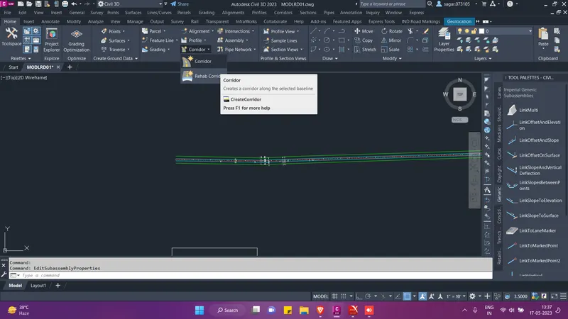
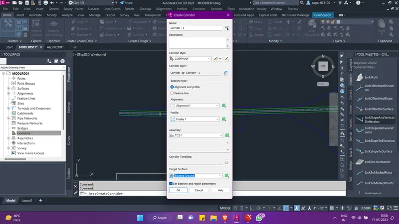
- Give the name as Corridor-01. Then select the alignment, profile, assembly and target surface. Then click on OK.
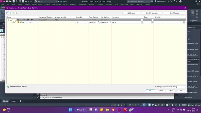
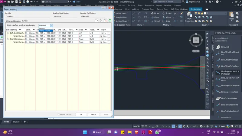
- Then again a pop-up menu will appear. Here go to the target column and under surface tab set the target as existing ground and click OK.
- The corridor for alignment 1 has been created. Refer the image below. Now we will add the other alignment too in the same model. For this, select the created corridor and from the contextual ribbion select corridor properties. The corridor property dialogue box will appear.
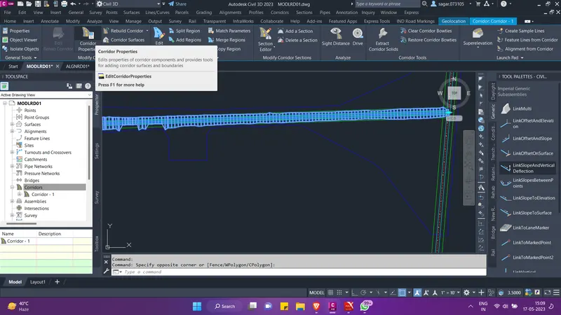
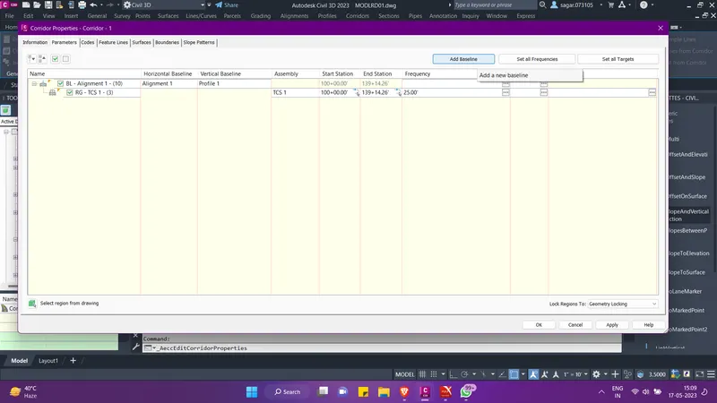
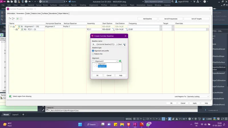
- There under the parameter tab, select "add baseline" option from the top. Then add alignment 2 as the new baseline. Click OK.
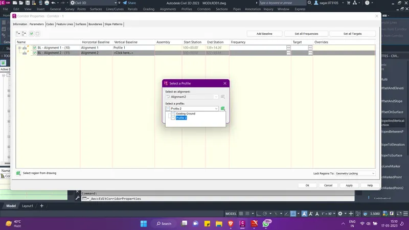
- Then under the vertical baseline column, select the respective profile for alignment 2.
- Then right click on the alignment 2 baseline and select the "add region". From the pop-up menu set the desired TCS for alignment 2 and click OK.
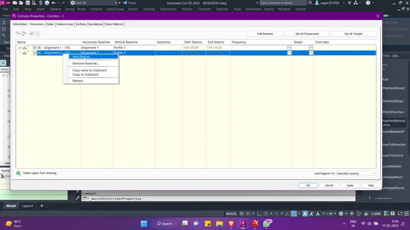
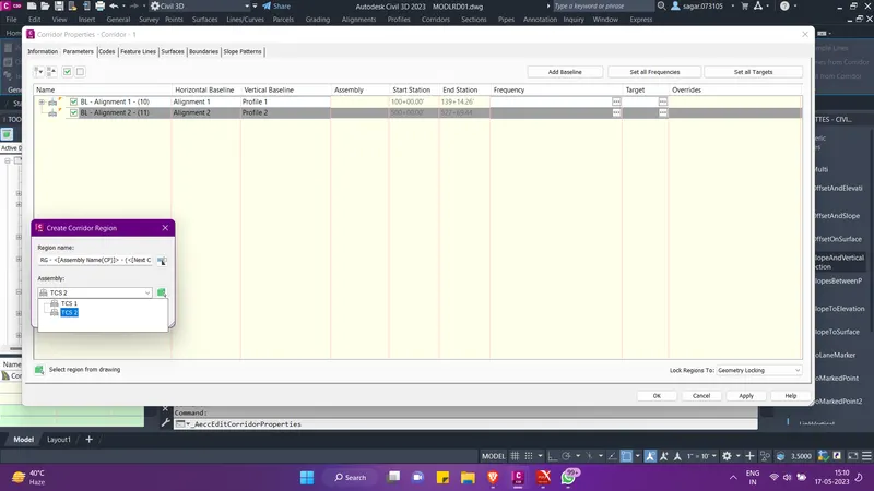
- Then go to target column and there under the surface tab, set the target as existing surface. Click OK. Then click on Apply and build the corridor.
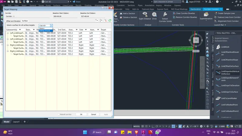
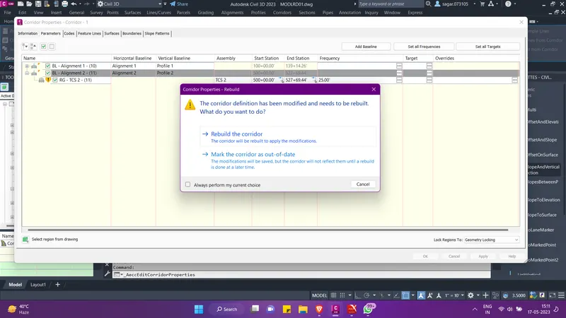
- Then select the entire corridor and hide it for sometime. Now we have to create the connected alignments and then split the corridor at appropriate station points for intersection modelling.
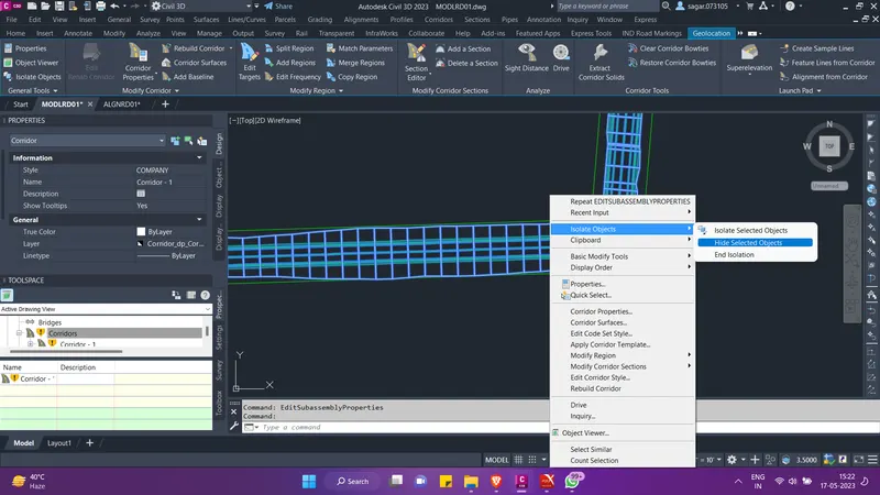
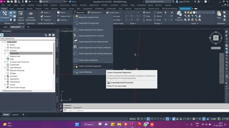
- To create the connected alignment, go to ribbion and under the create deisgn palette, click on alignment option and select "create connected alignment".
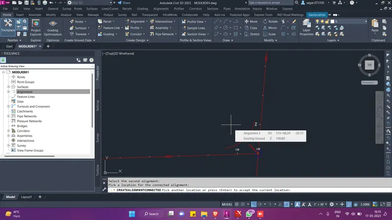
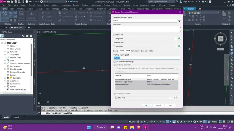
- Then to set the direction of the connected alignment, select the first aligment and then the second one. Press enter, then a pop-up menu will appear. Here give the name for the connected alignment CN-01.
- Then in the same menu, go to general tab and set the style for connected alignment.
- Then come to the design criteria tab and uncheck the criteria based design. Set the design speed as 45 mi/hr.
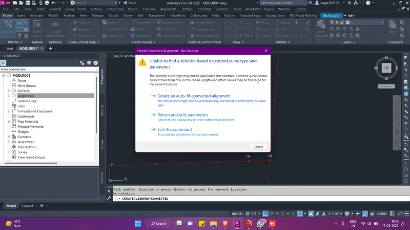
- Then come to the parameters tab and set the curve group type as circular fillet. Give curve radius as 30' , in and out offset at 12'.
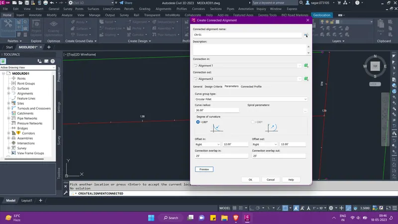
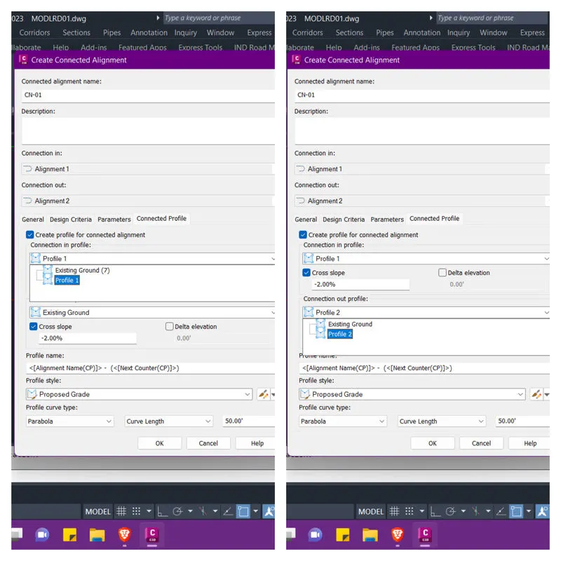
- Then come to the connected profile tab and set the connection in and connection out profiles as shown below and click OK. Follow the same process to create connected alignment on the other side too.
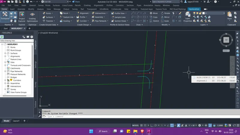
- The connected alignments will look something like this. Now we will end the isolation and split the corridor at three locations.
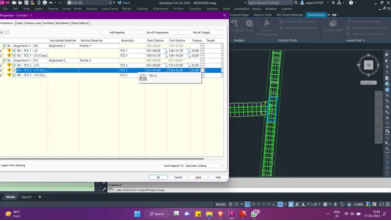
- After spliting the corridor properly, select the corridor, go to corridor properties and under baseline for alignment 2 select the second region. You can simultaneously observe that as you select the region in the dialogue box it refelets in the model also. So change this selected region with the variation of TCS-02 that we perviously created. Refer to the images below.
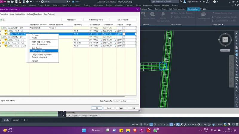
- Then we need to delete the selected region as shown below from the alignment 1.
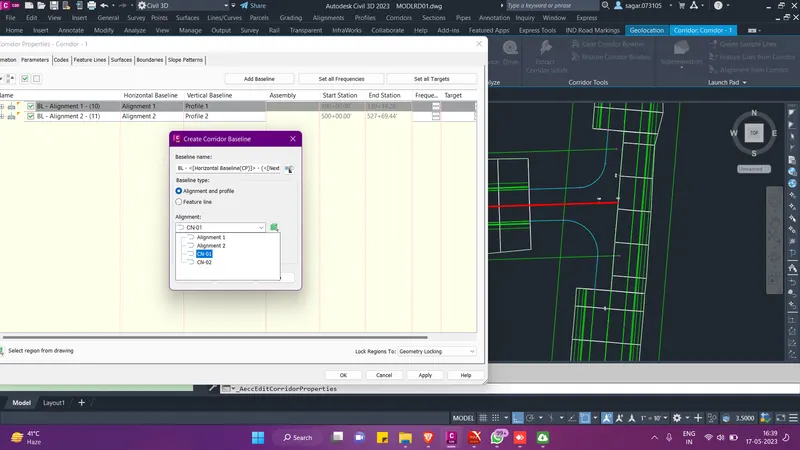
- Now, we will create new baselines for CN-01 and CN-02 alignment. So for this, select the corridor and go to corridor properties. There click on add baseline at the top.Then from the pop-up menu first select the CN-01 alignment.
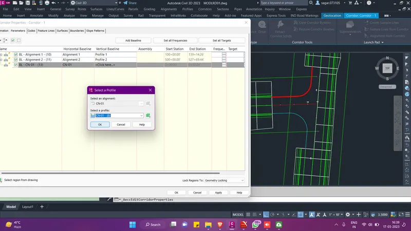
- Then select the respective profile for CN-01 alignment. Now, right click on this baseline and click on add region. Here we have to add a variation of TCS-01 which we created previously. Refer to the images below and follow the same procedure for CN-02 alignment.
- We also need to target the created baselines to the existing surface. For this go to target column. We also need to change the frequency for both of them.
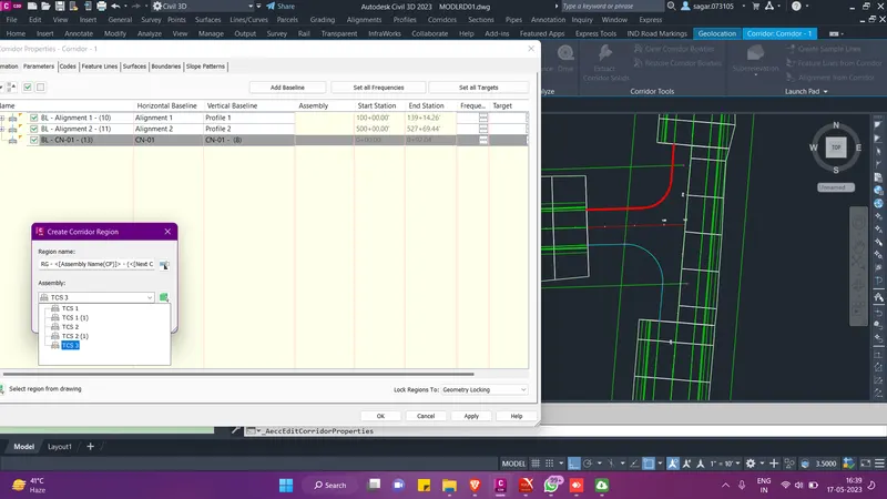
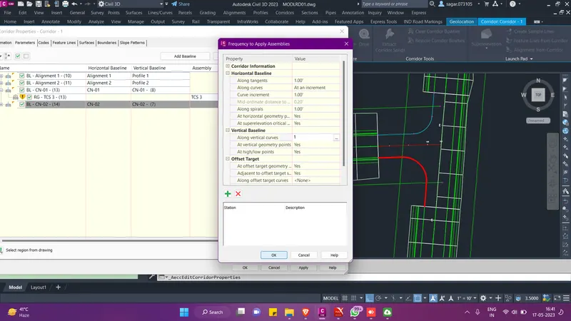
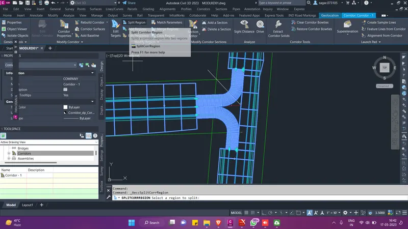
- After the completion of all the above steps, the corridor model for both the connected alignment will appear like this. Now we will draw a line as shown below on both the sides to further split these regions. After spliting, the CN-01 and CN-02 corridor model will be divided in two parts.
- We will then target the regions on the alignment 2 to its centerline and the regions on the alignment 1 to its centerline. Refer to the images below for better understanding.
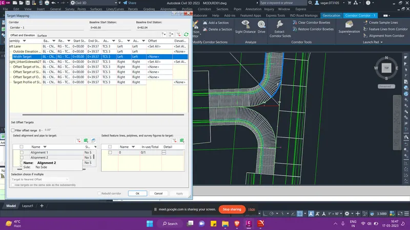
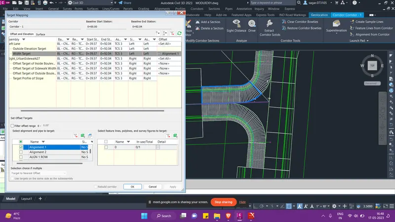
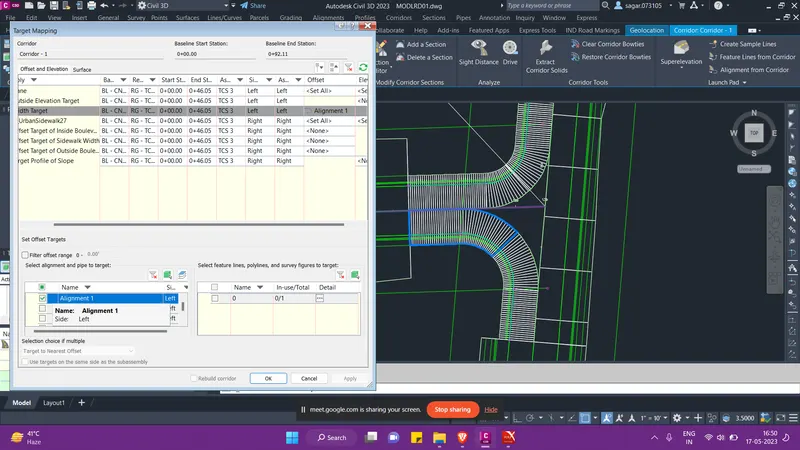
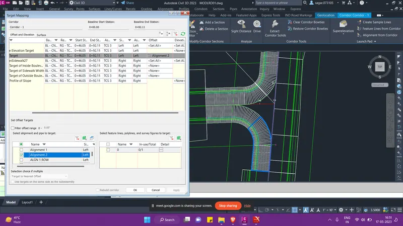
- We also have to keep in mind that along with the offset target, we also need to target the elevation. Beside the offset column in the above image there is the elevation column. So target profile of the respective alignment.
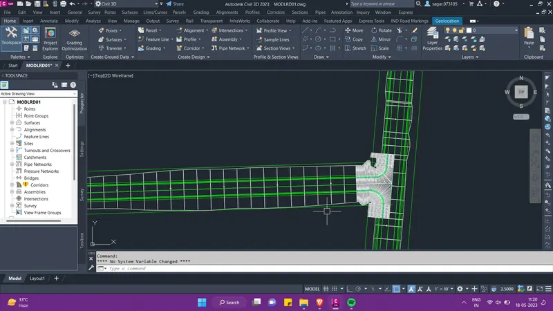
- Then after the completion of all the above steps the corridor model will look something like this. Then save this file and crete a data shortcut of this file.
- Now we will work out the Quantity for the designed alignment. For this, we will use the existing QTDSRD01 file.
- To work out the quantity for different items we need to know the count, running length, area or the volume of the respective item. So for this, we will refer to the TCS and then we will create the hatched area in our QTDSRD01 file. For example, we want to know the area of the shoulder region since we want to provide Type B stabilization below that. So on refering to the TCS we came to know that the shoulder width in 6'. Now we will create offset of 6' from the edge of lane and we will create a closed region. Then we will just hatch the entire region along the alignment.
- Then we will go to Analyse option in the ribbion and then we will select the QTO manager option. And there we will load our pay items list.
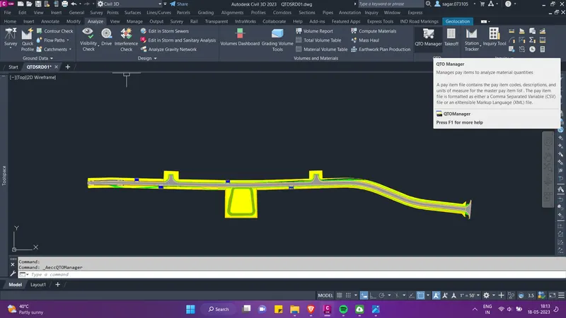
- Once the pay item list is loaded, we will find the type B stabilization by using its pay item ID, then we will select the hatched region and assign it to the respective pay item.
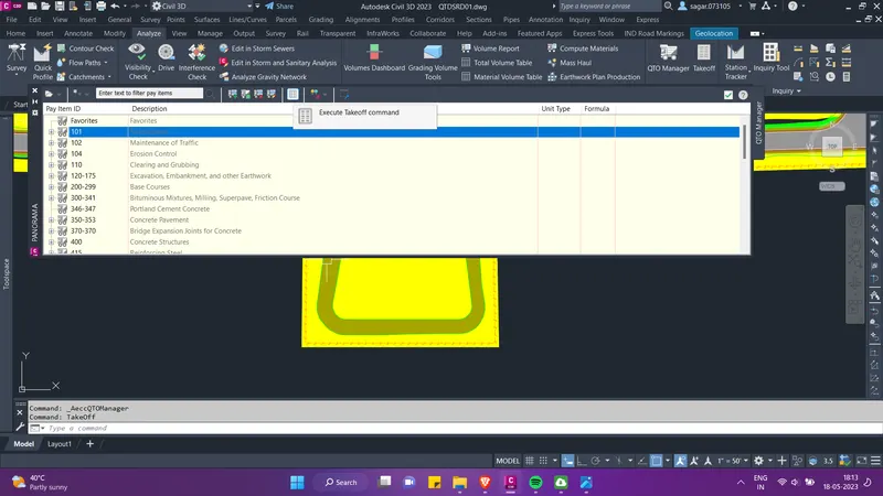
- Then we can go to "execute takeoff command" as shown below and we can find the quantity of the type B stabilization. Similarly we can work out the quantity of different item by using the QTO manager.
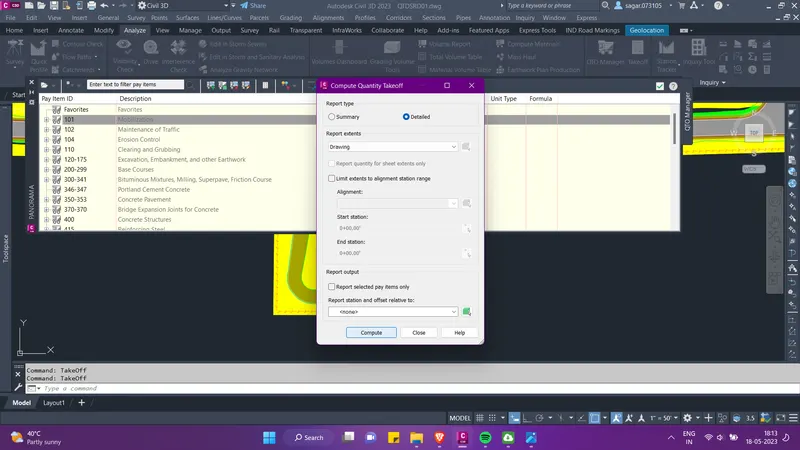
- The pay items for different regions is already added in the existing QTDSRD01 file. So we can just go to Analyze option in the ribbon and select Takeoff option which is present beside QTO manager. In the pop-up menu select report type as detailed and click on Compute. The quantities for all the item will be generated. The excel file containing all the quantities have been attached.
- Now we will create pipe network and pond file. We will name this file as PDPLRD01. In this file we will create the reference of all our centerline and offset alignments for both the roads. We will also create the reference of our existing ground in this file. We will also set the geolocation in this file.
- Then we will turn on the geo location and find the location of pond in the site area. Once we find a pond then we will create ployline around its boundry and and further create a feature line on the basis of the polyline.
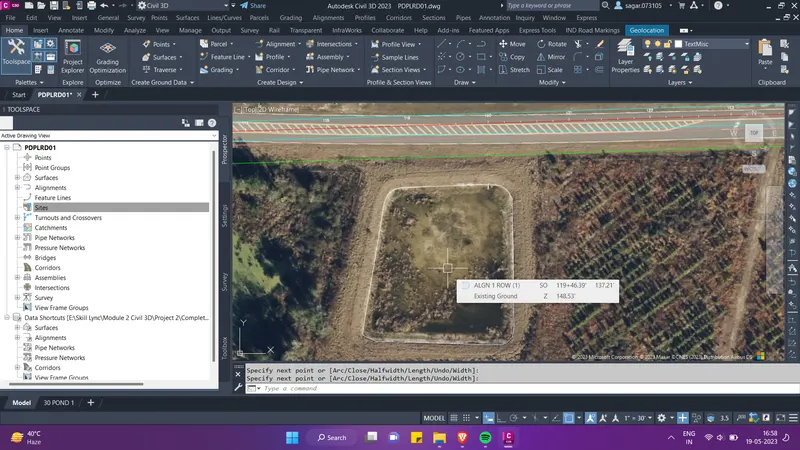
- For creating the freature line, go to create design palette in the ribbion, select feature line and then further select "create feature line from objects". A pop-up menu will appear, there give the site name and click on OK.
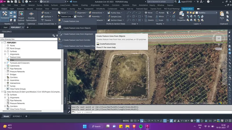
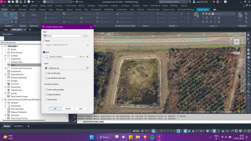
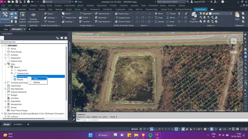
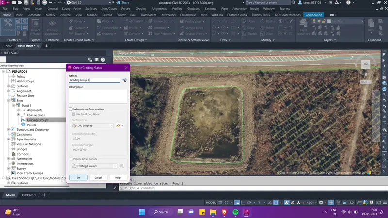
- Then we need to create grading group for which we will go to the prospector tab in the tool space and under Sites option, we will right click on grading group option and select "New". The from the pop-up menu give the name of the group and click OK.
- Then again go to the create design palette in the ribbion and select Grading option. Then select "grdaing creation tools". Then a tool palette will appear on the screen. There select "grade to elevation" option. Refer the images below.
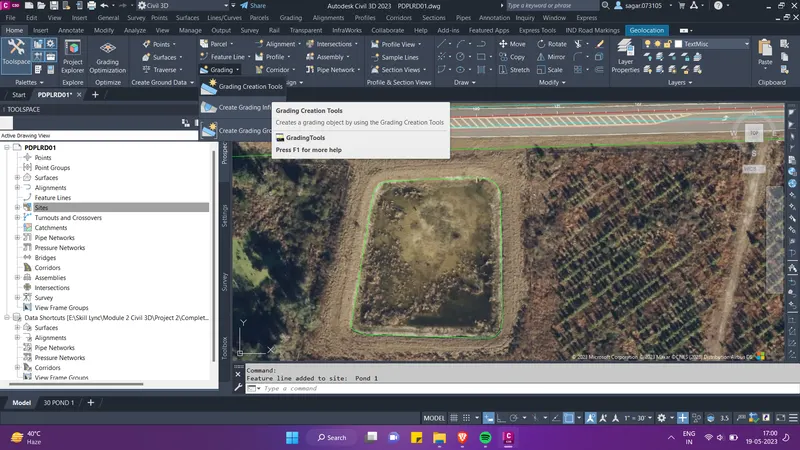
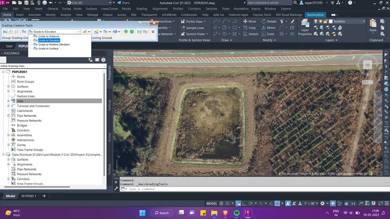
- Then select create grading as shown in the image below. Then we need to select the feature line. All the further steps are explained with the help of imgaes below.
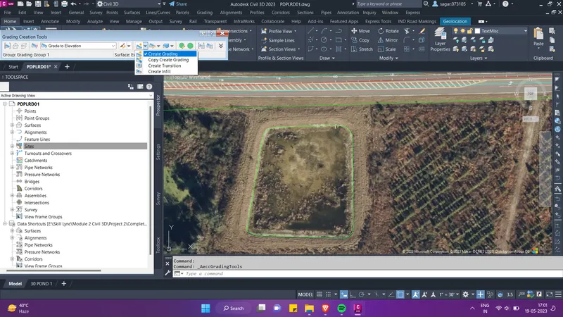
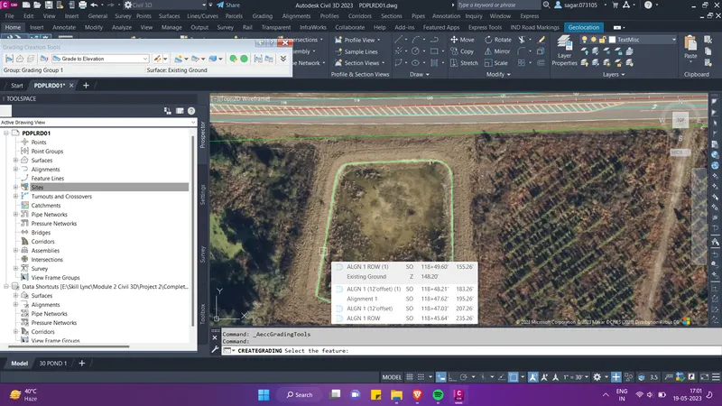
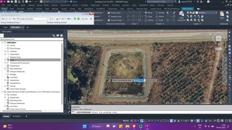
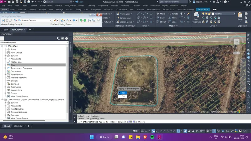
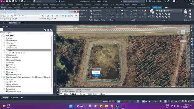
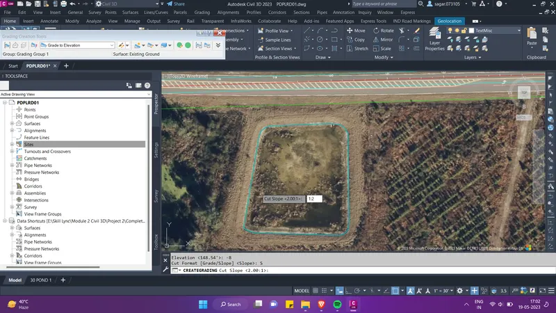
- Then we can observe in the image below, that the pond has been created. We can use "grade to distance" and "grade to surface" option after this for further detailing of pond slopes at the outer side of the pond.
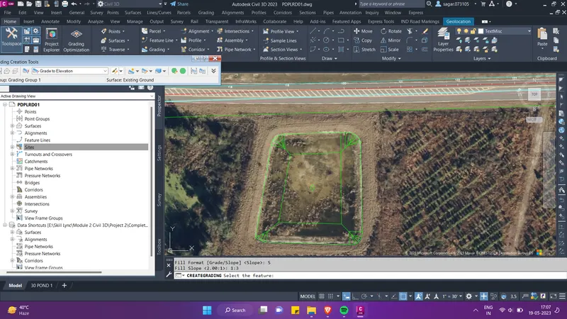
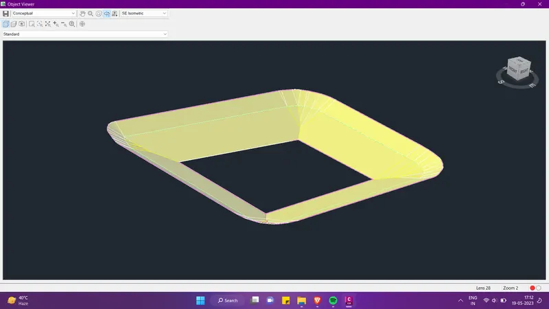
- Now for the creation of pipe network, we can create offset of the offset aligment. Then go to the create design palette in the ribbion and select Pipe Network option. We can create the pipe network from object. So select this option, set the direction of flow. Then a pop-up menu will appear.
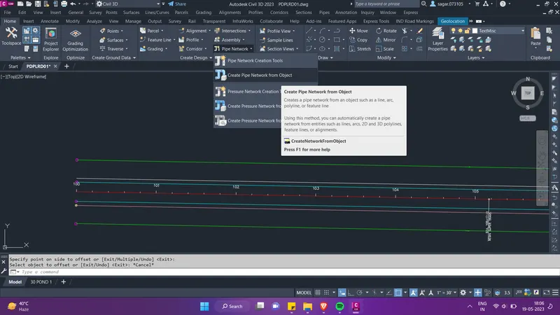
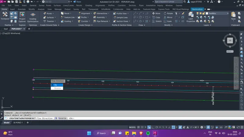
- Here give the name for the pipe network, select the pipe size and the structure type. Also set the surface. Then click on OK.
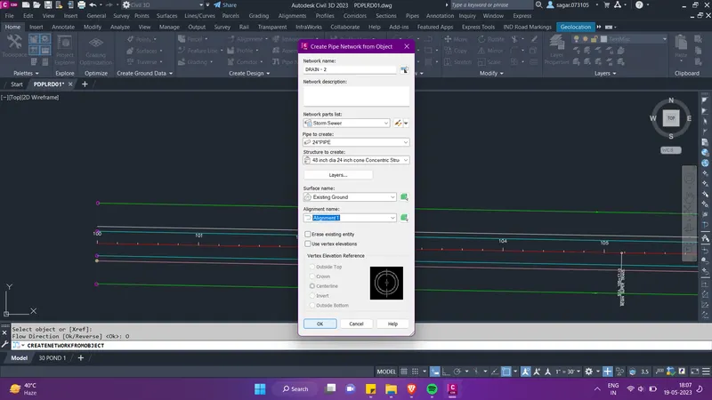
- Hence the pipe network and pond is created. Create the data shortcut of this file.
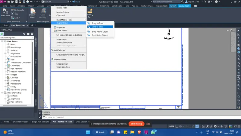
- Now we have to use the existing Plan sheets.dwt file and provide proper settings to the plan/profile and cross section viewports so that Civil 3d can plot our drawings in the desired format. So for this, open the plan sheets file which has been provided. Then go to the layout which has been created. Here select the title block, right click and set the display order to send to back.
- Then we can see the viewports for our profile and alignments. Since we require shorter viewport for our alignment and taller one for our profile, hence we will select the top viewport and adjust its height. Keep the bottom viewport taller for the profile.
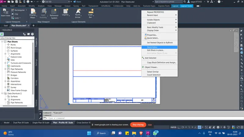
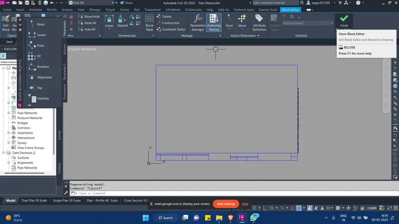
- After adjusting the height of the viewports, if you see a line as shown in the image below, then select the title block, right click and go to block editor. Here delete the line in the middle on the block and click OK.
- Then similarly, we have to edit the cross-section layout sheet as well. So for this, go to the cross-section layout sheet, here select the title block, right click and set the display order send to back. Then we can see the viewport for the cross-section layout sheet.
- We can edit the viewport, remove the grid lines if require. Then we will save this dwt file to the completed assignments folder.
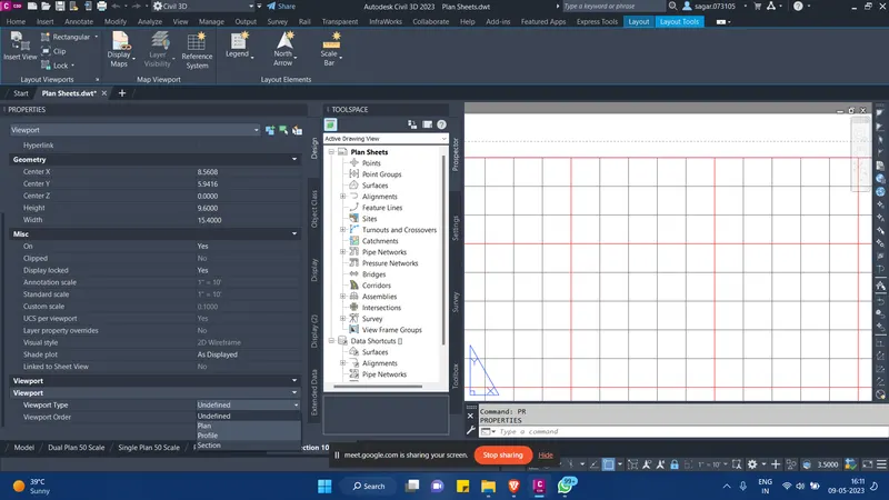
- Now we also have provided with the Sheet Set.dst file which have all the custom properties. We will use this file to manage all our sheets. We will add all the sheets in this file under Roadway Plans subset.
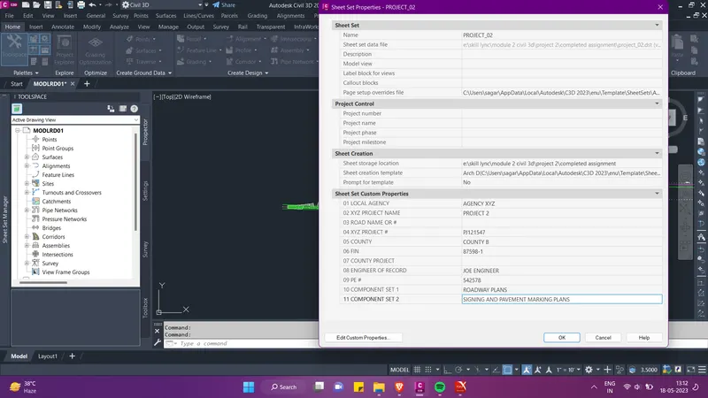
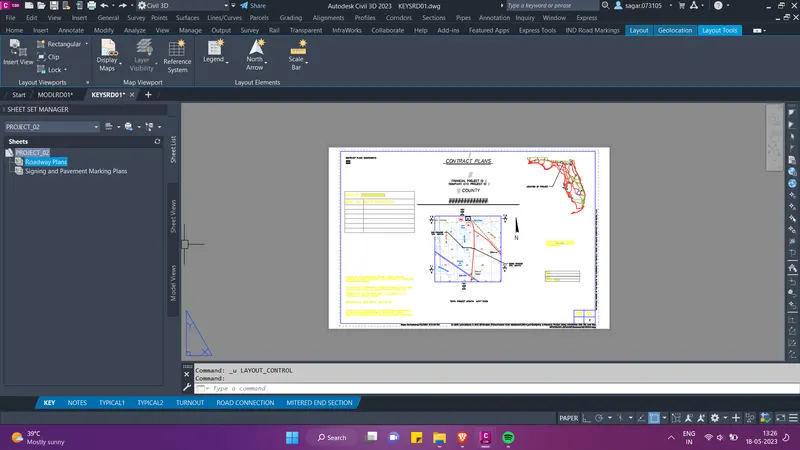
- We will also add the front layout sheets which consist of project notes and other details in this sheet set.
- For this, open the KEYSRD01 file. Then press Ctrl+4 to open the sheet set manager. Select PROJ-2 sheet set. Then from KEYSRD01 file, select all the layouts at the bottom as shown in the image below.
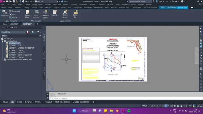
- Then drag and drop all the layouts from the KEYSRD01 file to the top of the PROJ-2 sheet set under Roadway Plans.
- As soon as we add the layouts to the sheet set, the layout start reflecting the project name and other details. Then further we can rename and renumber the layout sheets.
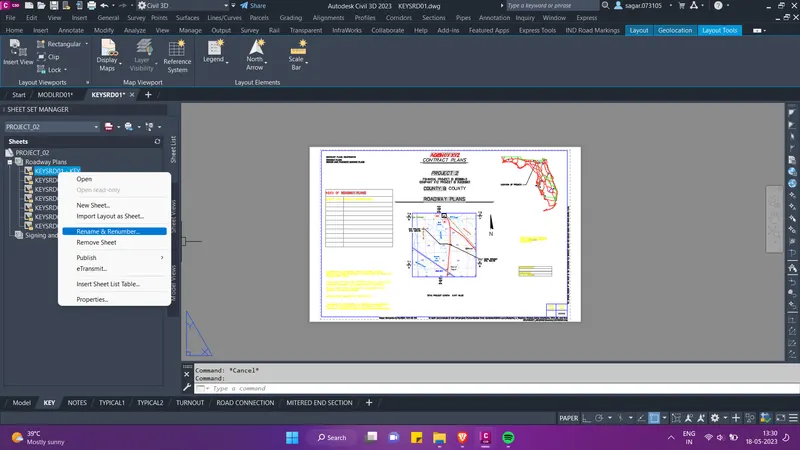
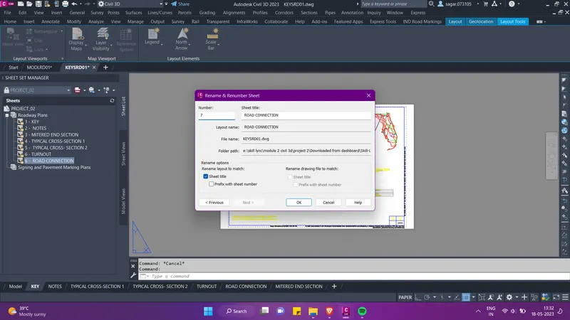
- Now we will create the CLIPRD01 file so that we can create the view frames for the alignment and profiles. Then further we will generate the plan sheets with the help of view fame groups. We have already created the data shortcut of our ALGNRD01 file, so we will directly create the reference of the data in the CLIPRD01 file.
- Then to make our drawing sheets presentable, we need to set the desired alignment properties for Cypress lake and Charles Terrace road in the existing CLIPRD01 file. We also need to remove the stationing of the offset alignment as well as the ROW alignment.
- In the images below you can see that the desired aignment properties has been applied to the alignment.
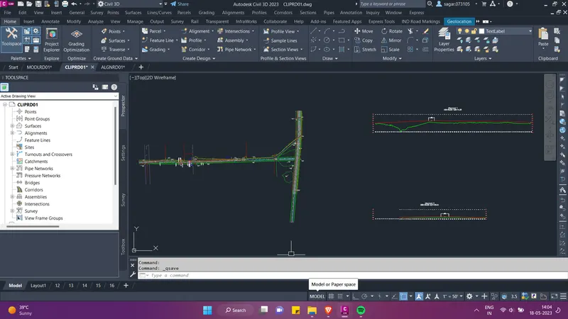
- As you can see in the above image, we have added XREF of our TOPORD01 file in the CLIPRD01 file. We have also created the profile using the surface for both the roads. It should be kept in mind that every time you create reference of some other file in the current file, we need to set the alignment styles and create the profiles again in the current file.
- Now we will create view frames in the CLIPRD01 file. So go to the prospector tab in the tool space, and right click on the view frames groups. A pop-up menu will appear, here select alignment 1 first and follow the steps below.
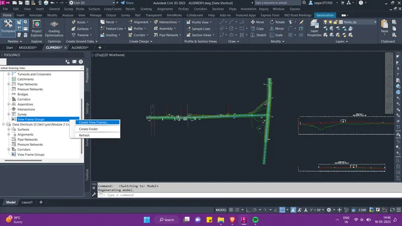
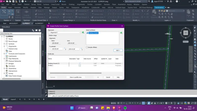
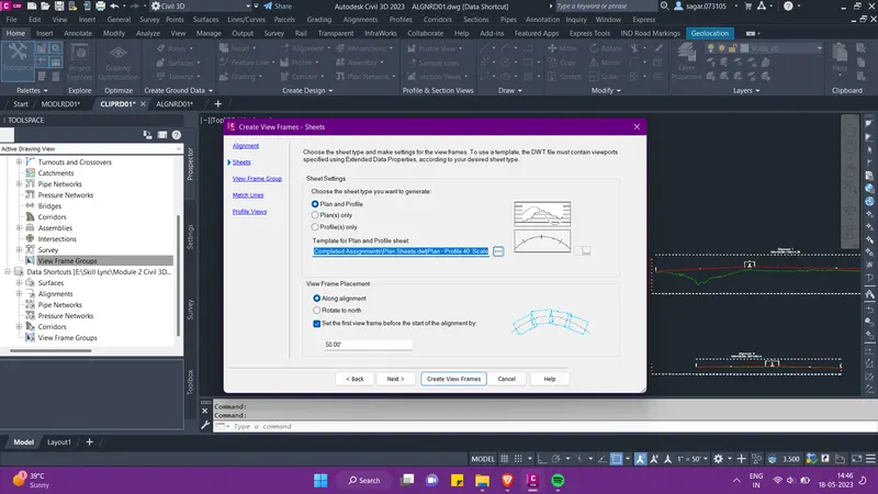
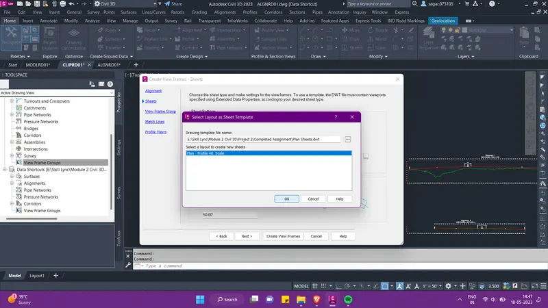
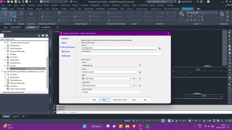
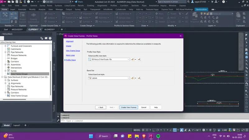
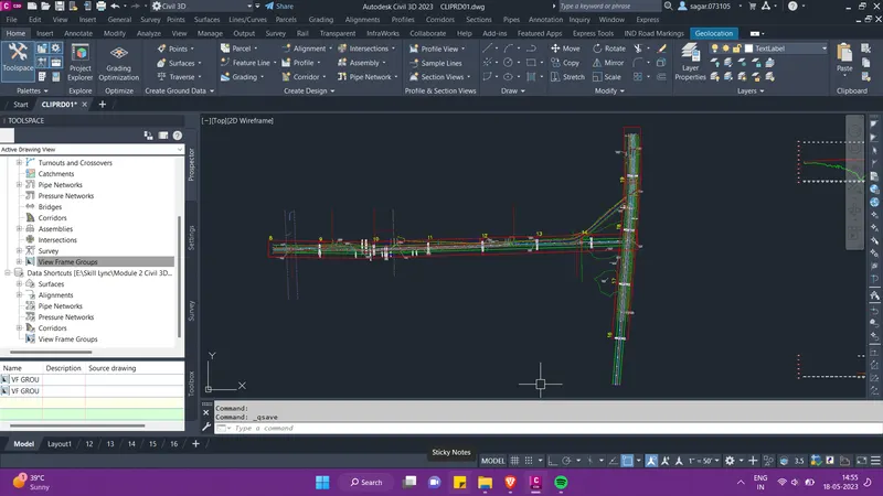
- As you can see that the view frames have been created for both the alignments. Now we have to refer to the assignment .PDF and add all appropriate notes to the plans profiles and profile views. We can use the QLEADER command for this.
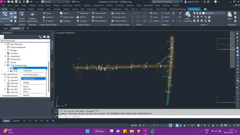
- Now we can create Plan sheets with the help of the dwt file that we created above. So go to the view frame group that we just created, right click on VF GROUP 01 and click on create sheets.
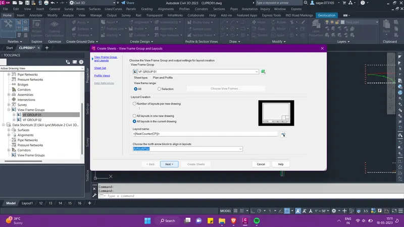
- Then from the pop-up menu select the view frame group, select "all layouts in the current drawing" option and click Next. Then select the PROJECT_2 sheet set. All the plan sheets will stay in the same sheet set. Then follow the steps below.
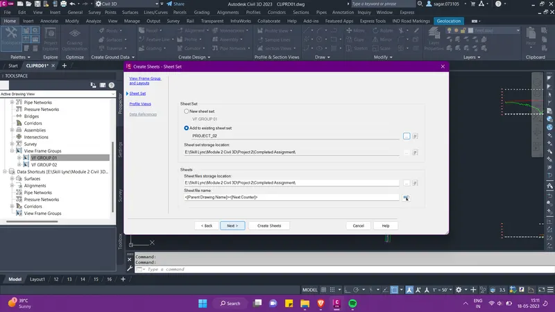
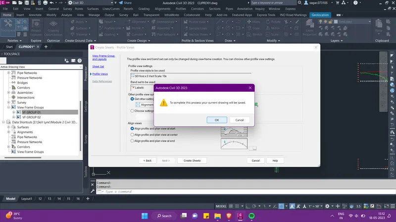
- Once the plan sheets are created it will look something like this. Press Ctrl+4 to open the sheet set manager. Then we can select all the created sheets and drag and drop it in the PROJECT_2 sheet set. Further we can rename and renumber all the sheets accordingly.
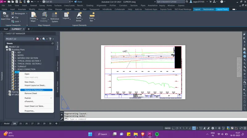
- Then we will follow the same procedure to create plan sheets for VF GROUP 02.
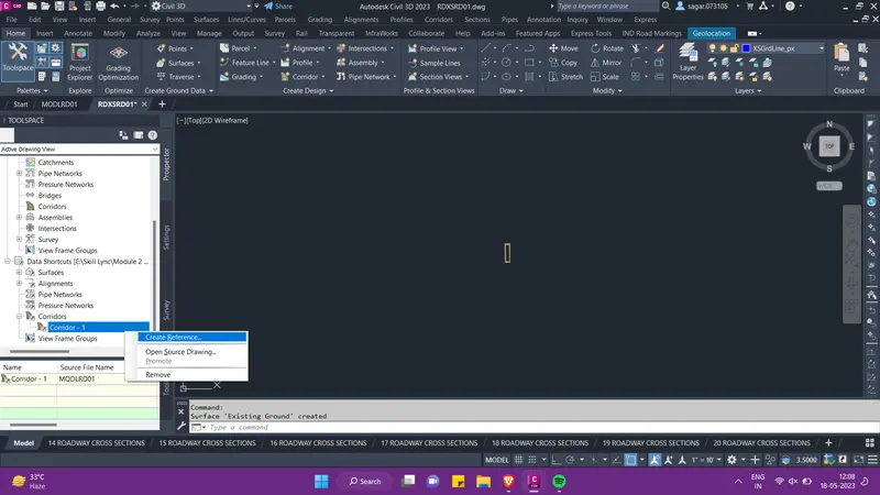
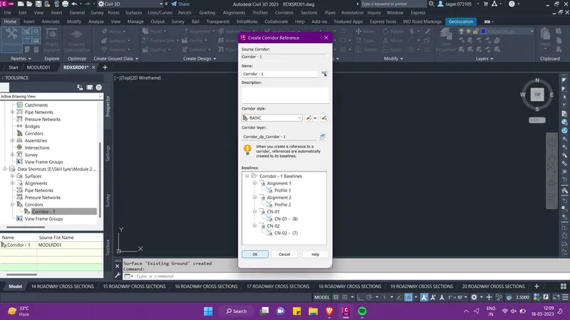
- Now we will create a file by the name RDXSRD01 in which we will create the cross-sections for both the alignments after which we will generate the cross-section sheets. We already created data shortcut of the MODLRD01 file. We will use the reference of this file in the RDXSRD01 file.
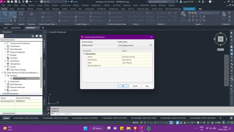
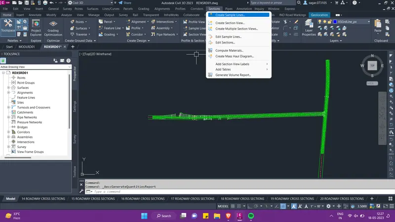
- Then for the creation of cross-setion sheets we will create the sample lines first for both the alignments. So go to the sections option in the Menu bar and select create sample line.
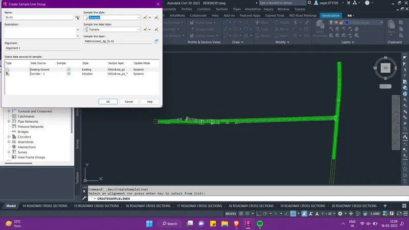
- Press enter then the pop-up will appear as shown below, select alignment 1 first to create sample lines. Give the name SL-01 and click OK.
- Then a tool palette will appear, here select "by range of stations" option as shown below. Then set the start and end range of stations and click OK. We need to follow the same procedure to draw sample lines for alignment 2.
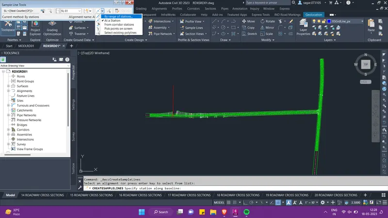
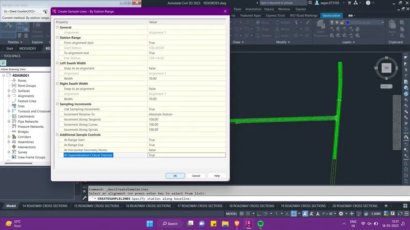
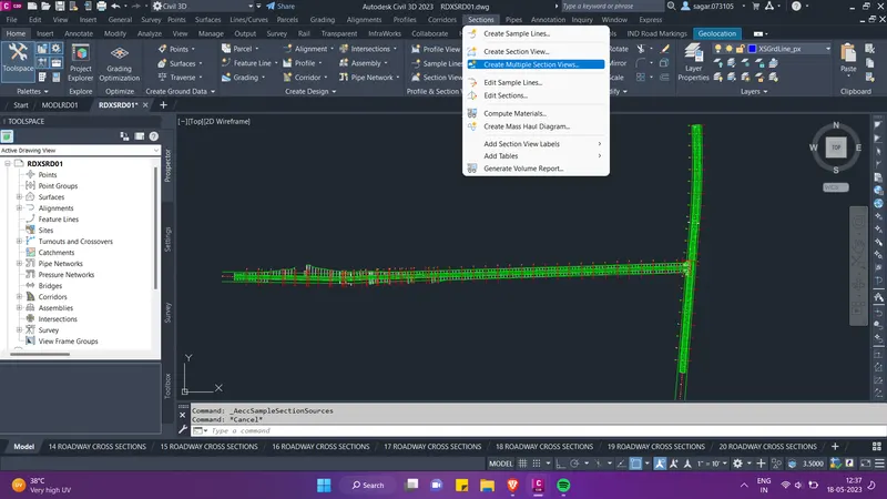
- After the sample lines is drawn for both the alignments, then we will again go to the sections option in the menu bar and select "create multiple section views". Then follow the steps as shown below.
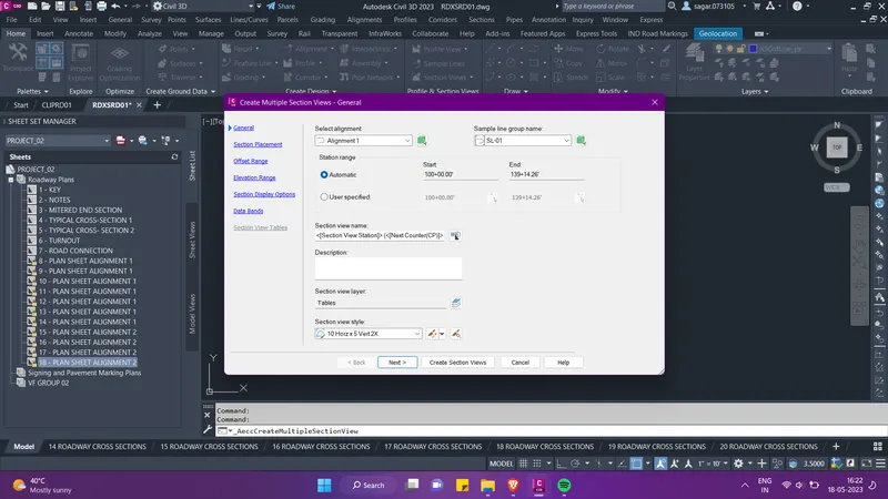
- Then we need to select the Plan sheet.dwt then click on Next. Then at the last click on create section views.
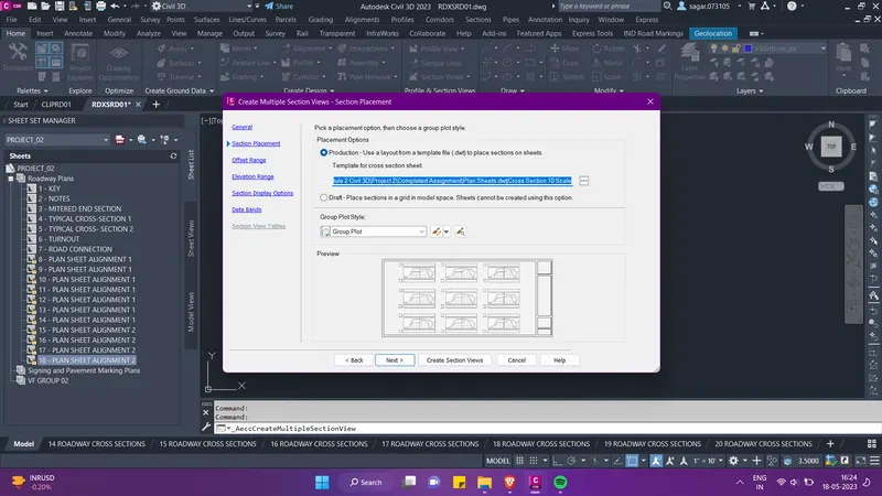
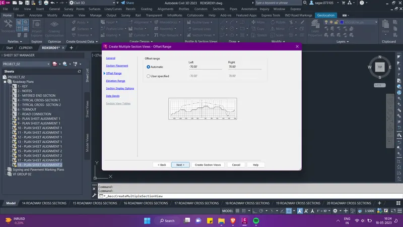
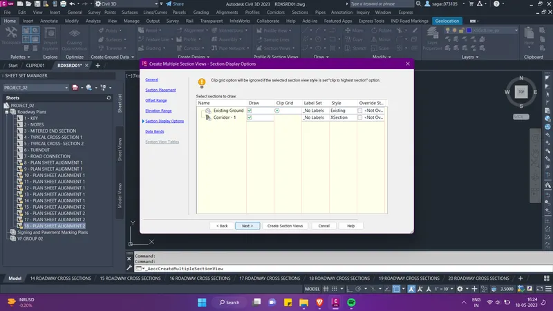
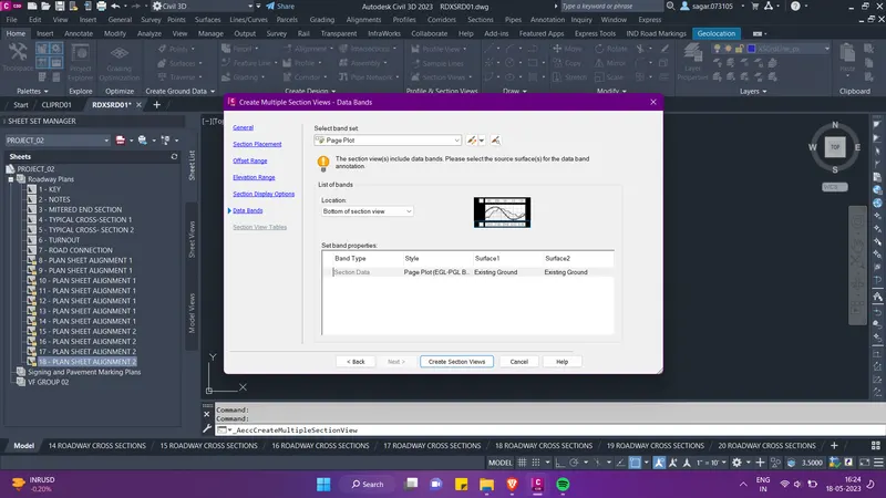
- After the creation of section views for alignment 1, we need to create the section views for slignment 2 by following the same steps as shown above. Then we will create section sheets.
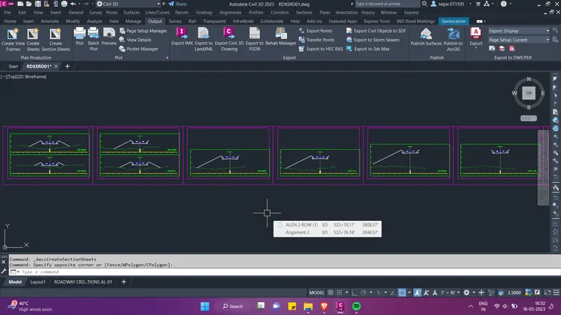
- For creating the cross-section sheets, go to the output option in the ribbion and then select create section sheets as shown below. Then a pop-up menu will appear, there select the alignment, sample line group and section view group for alignment 1.
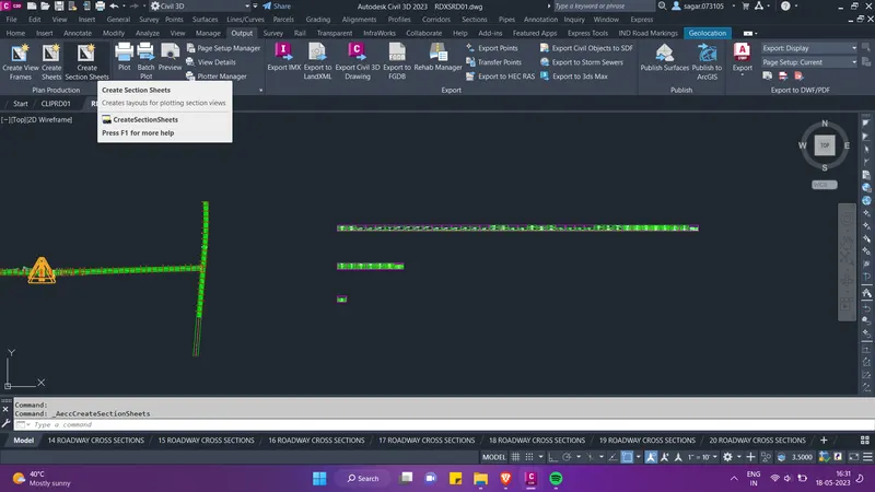
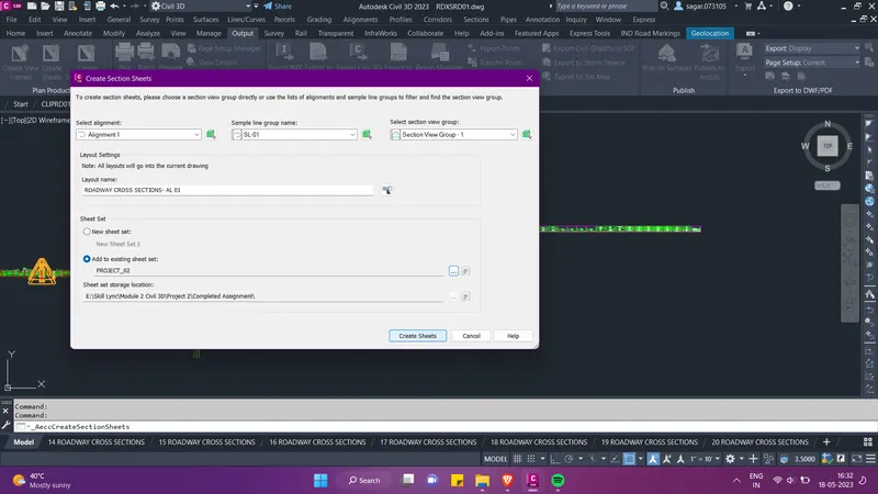
- Set the layout name and also the sheet set PROJECT_2 and the click on create sheets.
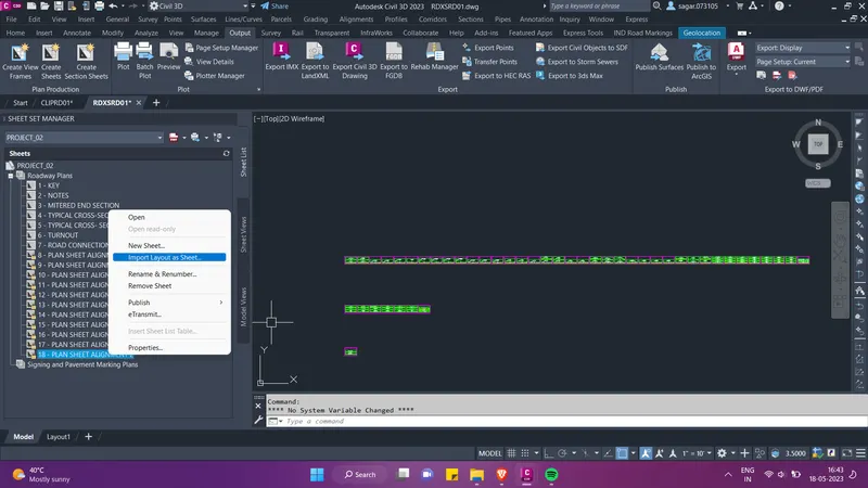
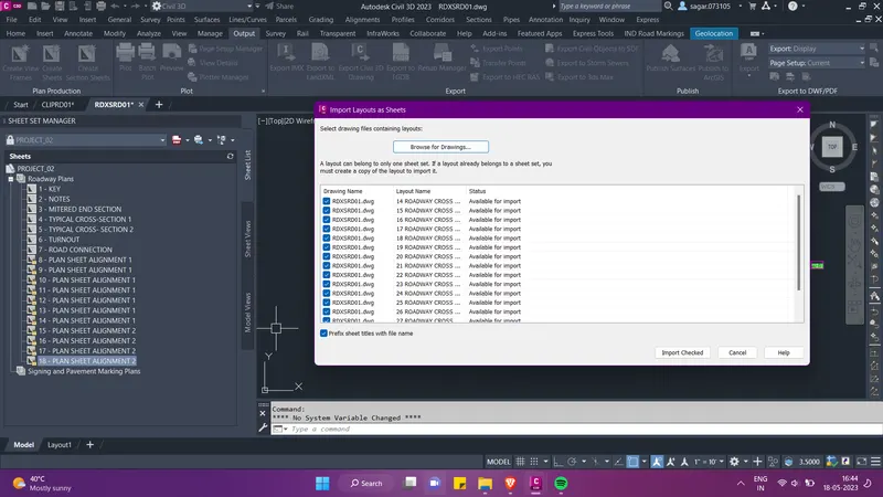
- We can add the created cross-section sheets in our sheet set PROJECT_2. For this, we can drag and drop the sheets in the sheet set manager by seleting all of them or we can right click on the last sheet after which we want to add the cross-section sheets, and select "import layout as sheets".
- Then we can select the RDXSRD01 file from the pop-up menu, select all thecross-section that you want to import and then click on "import checked" option.
- Once all the key plan sheets, plan and profile sheets and cross-section sheets are added to the PROJECT_2 sheet set, then we can move ahead with the publishing of the sheets as PDF.
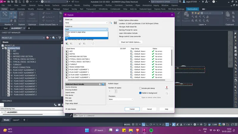
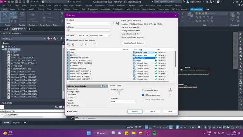
- For this, press Ctrl+4, the sheet set manager will appear. Then under the PROJECT_2 sheet set, select Roadway Plan subset, again right click on it and go to "Publish" option under which go to the "Publish Dialogue Box".
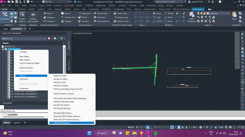
- Set the format as PDF and also the page setup as 11x17. Then click on Publish.