Project 2-Highway Assistant-Lane Changing Assistant
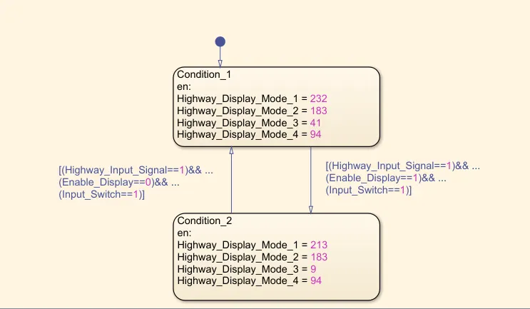
Requirement No 1 [Highway_DisplayUnit]:
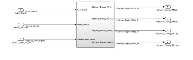
State flow logic implementation
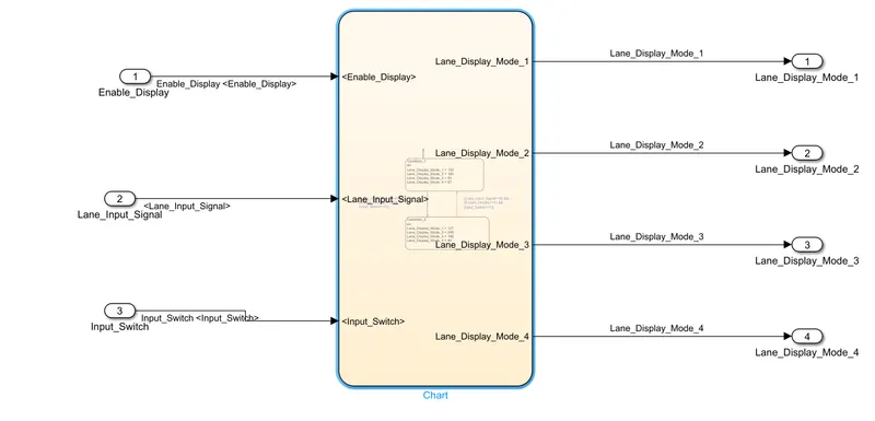
Requirement No 2 [Lane_DisplayUnit]:
Inputs to this particular subsystem are “Enable_Display”, “Input_Switch”, “Lane_Input_Signal”. These three input signals, when assigned to a particular value will give output signals of specific value. The output signals are “Lane_Display_Mode_1”, “Lane_Display_Mode_2”, “Lane_Display_Mode_3”, “Lane_Display_Mode_4”. The requirement must be implemented in the form of Stateflow logic.
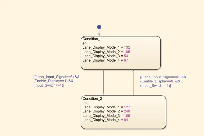
Requirement No 3:
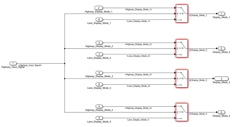
SLDD Creation:SLDD is created and linked to the model
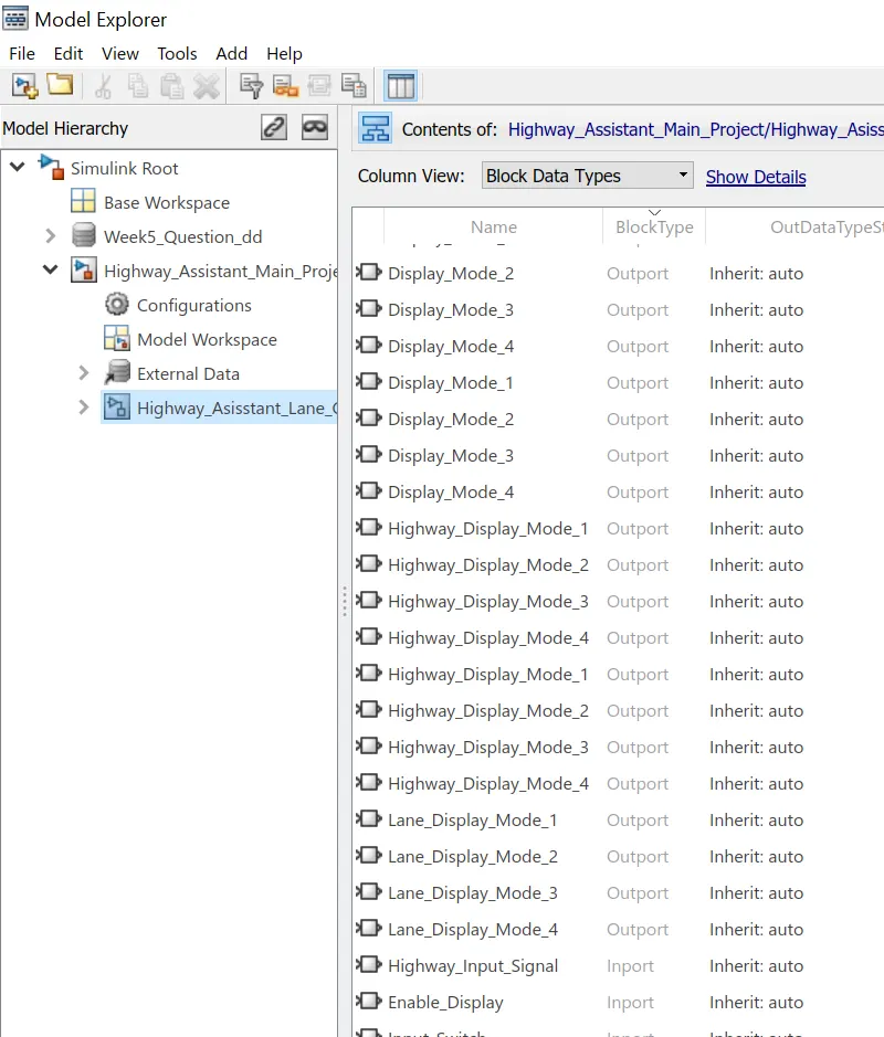
AUTOSAR port mapping
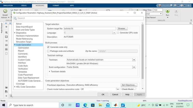
In the model window, on the Modeling tab, select Model Settings. In the Configuration Parameters dialog box, Code Generation pane, set the system target file to autosar.tlc. Click OK.
.
Select xml option and fill the packages;
Configure SR_interface,prefix: SRIF_,Data Element prefix is DE_ and for Sender Port Pp_,Receiver port Rp_
Now refresh and validate code to complete code mappings.
Model advisor
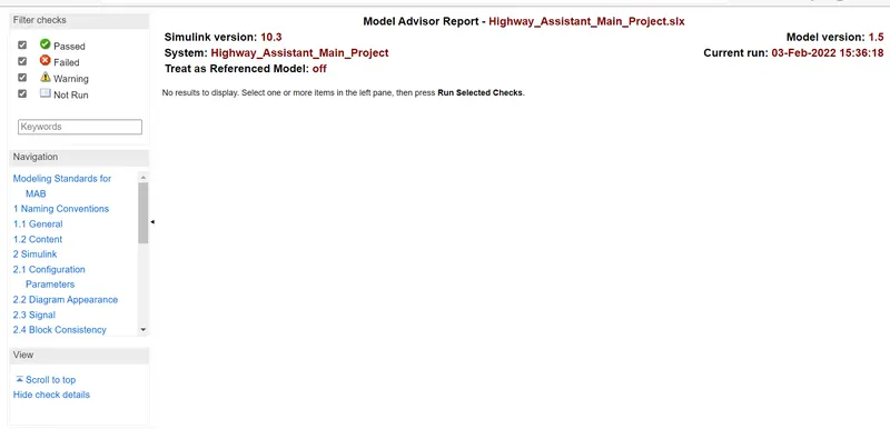
Run model advisor and generate report by clicking running selected checks.
AUTOSAR Code generation
To configure the model as a mapped AUTOSAR software component, open the AUTOSAR Component Quick Start. On the Apps tab, click AUTOSAR Component Designer. The AUTOSAR Component Quick Start opens
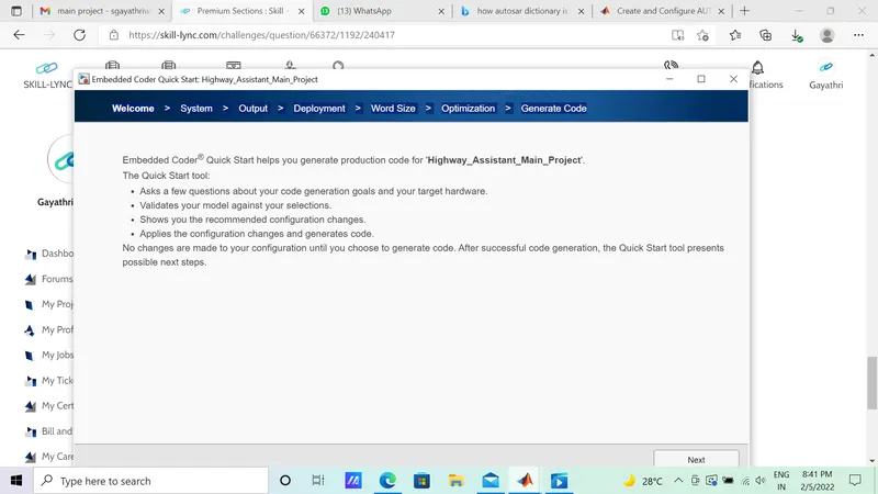
Attaching the model and necessary files: